
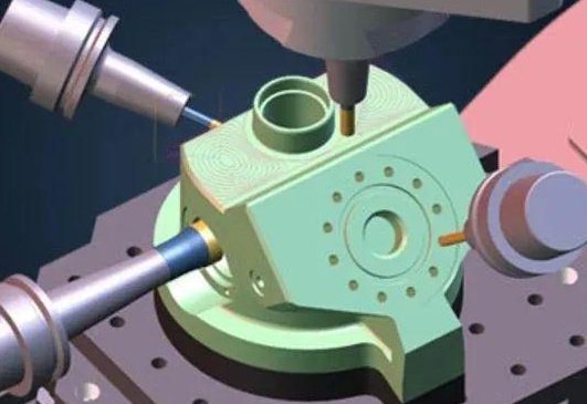
3+2 machining is often described as a type of 5-axis machining, but it does not behave the same way as full simultaneous 5-axis cutting. Understanding how 3+2 works, where it fits, and how it differs from continuous 5-axis control is essential for selecting the right process, machine tool, and CAM strategy.
Definition of 3+2 Machining
3+2 machining, also called positional 5-axis or indexed 5-axis machining, uses a 5-axis machine tool in a specific way:
- The rotary axes (usually A/B or B/C or A/C) are used to orient the workpiece or tool to a fixed angle.
- Once the tilt/rotation is set, only the three linear axes (X, Y, Z) move during cutting.
In practice, the machine “indexes” to a certain orientation using the 4th and 5th axes, then machines the part as if it were on a 3-axis machine. After one orientation is completed, the machine repositions the rotary axes to another angle, and the process repeats.
Definition of Full 5-Axis (Simultaneous) Machining
Full 5-axis machining, also known as simultaneous or continuous 5-axis machining, moves all axes together during cutting:
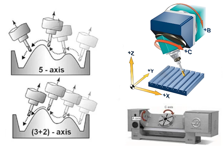
- Up to three linear axes (X, Y, Z) and two rotary axes (e.g., A and C) can move simultaneously.
- The tool vector (tool axis direction) changes continuously while material is removed.
Simultaneous 5-axis control enables complex surface machining, dynamic tool orientation, and continuous motion around the part, which cannot be replicated simply by indexing to fixed orientations.
Is 3+2 Machining Truly 5-Axis?
3+2 machining is technically a type of 5-axis machining because it uses a machine equipped with five controllable axes (three linear and two rotary). However, it is not full simultaneous 5-axis machining.
Key points:
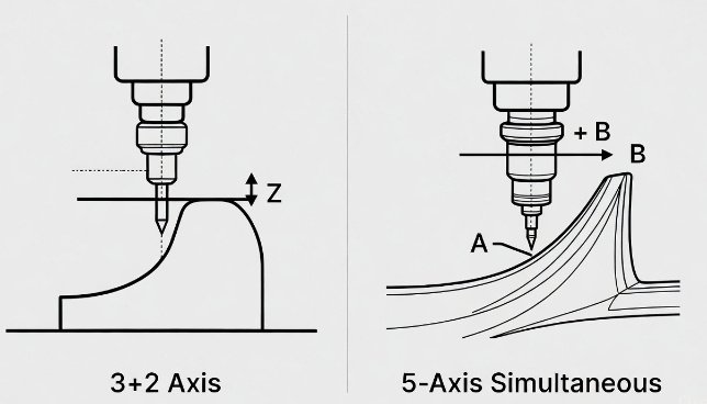
- 3+2 uses 5 axes, but only 3 axes move during cutting; 2 axes are set and held fixed.
- Simultaneous 5-axis machining uses up to 5 axes in continuous motion during cutting.
- From a classification standpoint, 3+2 is commonly grouped under 5-axis capabilities, but many practitioners explicitly distinguish “3+2” from “full 5-axis” to avoid confusion.
Therefore, 3+2 machining is “5-axis” in terms of machine capability and workpiece orientation, but not in terms of continuous toolpath motion.
Axis Configurations and Kinematic Basics
In both 3+2 and full 5-axis machining, the machine layout (kinematics) is fundamental. The most common mechanical configurations include:
| Configuration | Rotary Axes Location | Common Axis Names | Notes |
|---|---|---|---|
| Table-Table | Both rotary axes under the workpiece | A-axis (tilt) + C-axis (rotation) | Good for small to medium parts; common in 5-axis trunnion machines. |
| Head-Table | One rotary in the head, one in the table | B-axis (tilting head) + C-axis (rotary table) | Widely used in vertical machining centers for versatility. |
| Head-Head | Both rotary axes in the spindle head | B-axis + C-axis (or A-axis + B-axis) | Often used on large gantry-type or high-precision machines. |
Regardless of kinematic layout, 3+2 machining follows this pattern:
- Rotate/tilt the table or head to a specified angle.
- Lock or hold that orientation (the control maintains the set angle).
- Perform 3-axis milling (X, Y, Z) at that orientation.
- Repeat for additional orientations as needed.
How 3+2 Machining Works in Practice
A typical 3+2 cycle can be described in steps:
- The CAM system or programmer defines a local coordinate system (work plane) oriented to a particular surface or feature on the part.
- The post-processor converts that orientation into rotary axis positions (A, B, C angles) for the machine.
- The machine moves its rotary axes to those angles, often using G68.2 or similar transformation commands depending on control type.
- Once in position, 3-axis toolpaths (e.g., pocketing, drilling, contouring) are executed in the rotated coordinate system.
This process may be repeated for many planes and orientations, enabling access to multiple sides of a part in a single setup without continuous 5-axis motion.
Comparison: 3+2 vs Simultaneous 5-Axis
While 3+2 and simultaneous 5-axis use the same hardware, the motion strategy and application scope differ significantly. The table below summarizes key distinctions.
| Aspect | 3+2 Machining (Positional) | Simultaneous 5-Axis |
|---|---|---|
| Axis Motion During Cutting | 3 linear axes; rotary axes fixed at set angles | Up to 5 axes moving at the same time |
| Tool Orientation | Stepwise changes between operations | Continuously changing along the toolpath |
| Surface Capability | Suited to planar and moderately contoured features accessible from fixed angles | Suited to complex freeform surfaces and continuous blends |
| Programming Complexity | Closer to 3-axis; orientation management added | More complex; requires full 5-axis CAM strategies |
| Machine Control Requirements | Standard 5-axis control with positional capability | High-performance control with advanced interpolation |
| Typical Use | Multi-side machining, angled holes, access to undercuts | Aerospace blades, impellers, molds, medical implants |
| Toolpath Smoothness | Segmented; orientation changes between toolpaths | Continuous; orientation evolves within one toolpath |
Technical Impact on Accuracy and Surface Quality
From a technical standpoint, both 3+2 and simultaneous 5-axis machining depend on machine geometry, rotary accuracy, control algorithms, and calibration quality.
Geometric Accuracy
Important contributors to accuracy include:
- Rotary axis positioning accuracy and repeatability.
- Alignment of rotary axes relative to linear axes (centerlines, offsets).
- Kinematic calibration (e.g., volumetric compensation, pivot point offsets).
In 3+2 machining, because the rotary axes are static during cutting, interpolation errors from dynamic 5-axis motion are absent. Accuracy is primarily determined by the precision with which the rotary axes index and the quality of the underlying 3-axis motion.
Surface Finish and Toolpath Behavior
3+2 machining typically produces surface finish characteristics similar to 3-axis machining:
- Surface scallops and stepovers depend on tool diameter, stepover, and stock allowance.
- Any orientation-induced surface mismatch occurs at boundaries where one indexed orientation meets another.
Simultaneous 5-axis machining can generate more uniform surfaces on complex geometry by continuously aligning the tool, but it is more sensitive to:
- Feed interpolation quality.
- Look-ahead capability of the CNC control.
- Jerk and acceleration limits on rotary axes.
Programming and CAM Considerations
CAM software plays a central role in determining whether a 5-axis machine is used for 3+2 or full 5-axis work.
Work Planes and Coordinate Systems
For 3+2 machining, CAM programmers typically:
- Define multiple workplanes or construction planes aligned to individual faces or features.
- Assign drilling, pocketing, contouring, or 3D finishing toolpaths to each workplane.
- Rely on the post-processor to translate workplane orientation into rotary axis commands.
Typical control mechanisms include coordinate rotation and transformation functions that relate the part coordinate system to the machine axes.
Toolpath Types
In 3+2 machining, the following 3-axis strategies are reused in inclined planes:
- 2D pockets, profiles, and slots.
- Drilling, tapping, and boring at angles.
- 3D surface machining where most geometry can be accessed from fixed orientations.
For continuous 5-axis machining, dedicated 5-axis strategies are employed, such as swarf cutting, 5-axis flowline, and multi-axis contouring, which manage both tool position and tool orientation along freeform surfaces.
Typical Applications of 3+2 Machining
3+2 machining is particularly effective in situations where multiple faces or angled features must be completed in as few setups as possible, but the geometry does not require continuous 5-axis motion.
Multi-Side Machining in One Setup
Parts that would normally need several 3-axis setups can often be completed in a single clamping on a 5-axis machine using 3+2 orientations. Examples include:
- Prismatic components with features on five sides.
- Housings, brackets, and blocks with angled ports or slots.
- Complex fixtures and tooling plates requiring multi-face machining.
Angled Holes and Threaded Features
3+2 machining excels at drilling and tapping holes at non-orthogonal angles. The rotary axes orient the part so that drilling is performed along a straight axis, using standard cycles for:
- Deep holes requiring tool guidance along a linear axis.
- Threaded holes where perpendicularity to the local surface is required.
- Intersecting passages for fluid or gas channels in manifolds and valve bodies.
Access to Under-Cuts and Hidden Geometry
By tilting the part or tool, 3+2 can expose geometry that would be unreachable on a pure 3-axis machine. An example is machining a pocket wall that is partially obstructed in the default orientation. The programmer selects an orientation that provides line-of-sight access while still using standard 3-axis toolpaths.
Benefits of 3+2 Machining on a 5-Axis Platform
Using 3+2 on a 5-axis machine provides several concrete advantages:
- Reduction in number of setups and re-fixturing.
- Improved positional accuracy between multiple faces of a part.
- Better tool access and shorter tools due to part reorientation.
- Reuse of well-understood 3-axis toolpaths in multiple orientations.
Setup Reduction and Positional Integrity
Fewer setups reduce cumulative positioning errors and eliminate alignment steps on secondary fixtures. Features machined in a single setup can be referenced more accurately to each other than features that are produced in separate clampings on a 3-axis machine.
Tool Length and Rigidity
By rotating the part, 3+2 machining can allow shorter tools to reach deep features from more favorable angles. Shorter tool overhang improves rigidity, reduces deflection, and can enhance surface finish and dimensional control compared to using long-reach tools in a single orientation.
Limitations and Considerations of 3+2 Machining
3+2 machining is not a universal solution; its applicability depends on part geometry, tolerance requirements, and production volume.
Geometry Accessibility
3+2 machining can only handle geometry that is accessible from a finite set of static orientations. Continuous freeform shapes that require dynamic reorientation of the tool throughout the cut are better suited to full 5-axis machining.
Transition Regions Between Orientations
At boundaries where one indexing orientation meets another, the risk of slight steps or mismatches increases. These transitions are influenced by:
- Accuracy of rotary axis positioning.
- Consistency of toolpath parameters across orientations.
- Tool deflection differences between setups.
Careful planning of orientation changes, overlap zones, and toolpath blending can reduce visible boundaries, but the process is not as continuous as a single 5-axis trajectory.
Programming Effort
Although 3+2 programming is generally easier than full 5-axis programming, managing many workplanes and orientations still requires methodical organization. Clear naming conventions, consistent coordinate system practices, and rigorous post-processor configuration are important to prevent orientation errors.
Machine Tool Requirements for Effective 3+2
Not all 5-axis machines deliver the same performance in 3+2 operations. Key requirements include:
- Precise rotary axes with adequate torque and clamping.
- Control functions for tilted workplanes and coordinate transformations.
- Reliable probing and calibration routines.
Rotary Axis Specification
Relevant rotary axis parameters include:
- Positioning accuracy (e.g., within a few arc-seconds for high-precision work).
- Repeatability (the ability to return to the same angle reliably).
- Braking or clamping force to hold position under cutting loads.
- Resolution of the feedback system (encoder or scale) for fine angular control.
In 3+2 machining, once the axis is indexed and clamped, the static stiffness of the rotary system and its clamping mechanism becomes the primary factor in resisting cutting forces.
Control Features
For 3+2, the control must support:
- Rotated coordinate systems and tilted planes.
- Tool length compensation in the tilted frame.
- Fixture offsets that remain valid when the part is rotated.
Common control brands implement functions for coordinate rotation, tool center point control, and kinematic transformation that enable the same part program to be run with different fixtures or rotary configurations once properly set up.
Measurement, Calibration, and Verification
To maintain dimensional accuracy in 3+2 machining, careful measurement and calibration are necessary.
Rotary Centerline Calibration
The relationship between the rotary axes and the linear axes must be accurately characterized. This includes:
- Measuring pivot point offsets for tilting axes.
- Determining centerlines of rotation relative to the machine coordinate system.
- Compensating for small misalignments through control parameters.
On-Machine Probing and Verification
On-machine probing is commonly used to:
- Set work offsets after indexing to a new orientation.
- Verify critical features without unloading the part.
- Check and adjust for small setup deviations before running production cycles.
When to Use 3+2 vs Full 5-Axis Machining
The choice between 3+2 and full 5-axis should be based on part geometry, required surface quality, available equipment, and programming resources.
Situations Favoring 3+2 Machining
3+2 is usually the preferred approach when:
- The part has multiple faces or angled features but relatively simple surface geometry.
- Toolpaths can be represented as standard 3-axis operations from several orientations.
- The objective is to reduce setups and improve positional relationships, not to sculpt complex freeform surfaces.
Situations Favoring Simultaneous 5-Axis Machining
Full 5-axis machining is more appropriate when:
- The part has complex, smoothly varying 3D surfaces that must be machined in a continuous pass.
- Tool orientation must change constantly to keep the tool normal to the surface or within specific lead/lag angles.
- Surface continuity across the entire geometry is critical and orientation transitions must be minimized.
Economic and Practical Considerations
From a practical perspective, many shops acquire 5-axis machines and initially rely heavily on 3+2 machining due to its lower programming complexity and ease of adoption. This allows them to:
- Use existing 3-axis CAM knowledge and workflows.
- Gradually integrate more complex 5-axis toolpaths as experience increases.
- Leverage the 5-axis hardware immediately for setup reduction and improved access.
3+2 machining offers an effective balance between capability and complexity. It can deliver many of the setup and accessibility advantages of 5-axis equipment without requiring the full level of programming sophistication associated with continuous 5-axis toolpaths.
Conclusion
3+2 machining uses five axes in total (three linear and two rotary) and is implemented on 5-axis machine tools, so it is legitimately categorized as a form of 5-axis machining. However, it differs fundamentally from full simultaneous 5-axis machining because only three axes move during cutting while the two rotary axes remain fixed at specified orientations.
For parts with multiple faces, angled features, and moderate geometric complexity, 3+2 machining provides significant benefits in setup reduction, positional accuracy, and tool accessibility using familiar 3-axis toolpaths in inclined coordinate systems. For highly complex freeform surfaces that demand continuous tool orientation control, simultaneous 5-axis machining remains the appropriate choice.
Understanding these distinctions enables informed decisions about machine investment, process planning, and CAM strategy, ensuring that each part is produced using the most suitable combination of axis control and machining method.
FAQ About 3+2 and 5-Axis Machining
Is 3+2 machining considered 5-axis machining?
Yes. 3+2 machining is considered a form of 5-axis machining because it uses five controllable axes on the machine: three linear axes and two rotary axes. However, during cutting only the three linear axes move, while the rotary axes are indexed to fixed angles. It is different from full simultaneous 5-axis machining, where all axes can move together at the same time.
When should I use 3+2 instead of full 5-axis machining?
Use 3+2 machining when the part has multiple faces or angled features that can be accessed from a set of fixed orientations and do not require continuous tool orientation changes. Typical cases include multi-side prismatic parts, angled holes, and features that become accessible when the part is tilted. Use full 5-axis machining when the geometry has complex freeform surfaces or when the tool must change orientation continuously along the toolpath to maintain surface quality and access.
Is 3+2 machining easier to program than full 5-axis?
In most cases, 3+2 machining is easier to program than full 5-axis machining. It relies primarily on 3-axis toolpaths applied in different tilted workplanes, so the programmer can reuse familiar 2D and 3D strategies. Full 5-axis machining requires additional control over tool orientation along the path, more parameters, and deeper understanding of machine kinematics and collision avoidance.
Does 3+2 machining require special CAM software?
3+2 machining requires CAM software that supports multiple workplanes or coordinate systems and can output 5-axis positional code. Many mid-range and high-end CAM systems support 3+2 functions even if they do not offer full simultaneous 5-axis modules. The post-processor must be configured to translate workplane orientations into rotary axis commands and appropriate coordinate transformations for the specific machine and control.
