
5-axis machining enables the production of complex, high-precision parts in fewer setups than traditional 3-axis methods. To fully benefit from the technology, engineers must understand how design decisions affect manufacturability, cost, quality, and lead time. This guide presents practical, engineering-focused guidelines for designing components specifically for 5-axis CNC machining.
About 5-Axis Machining Fundamentals
Effective design for 5-axis machining starts with a clear understanding of how these machines move and what makes them different from 3-axis equipment.
Machine Configurations and Axes of Motion
5-axis CNC machines typically combine three linear axes (X, Y, Z) with two rotational axes (A, B, or C). Common configurations include:
- Trunnion-style: rotating table with tilting axis (e.g., A-axis tilt + C-axis rotation)
- Swivel-head: tilting/rotating spindle head with a fixed or rotary table
- Hybrid machines: combinations of swiveling head and rotary table
Designers should assume that the part may be oriented and tilted in multiple ways during machining. Surfaces need to be accessible not only line-of-sight from above but also from side and angled directions. Each configuration imposes different limits on part size, reachable features, and efficient tool orientations.
Simultaneous vs Indexed 5-Axis Machining
5-axis machining can operate in two main modes:
- Indexed (3+2) machining: the rotary axes position the part, then remain fixed while 3-axis cutting occurs
- Simultaneous 5-axis machining: all or most axes move in coordination during cutting
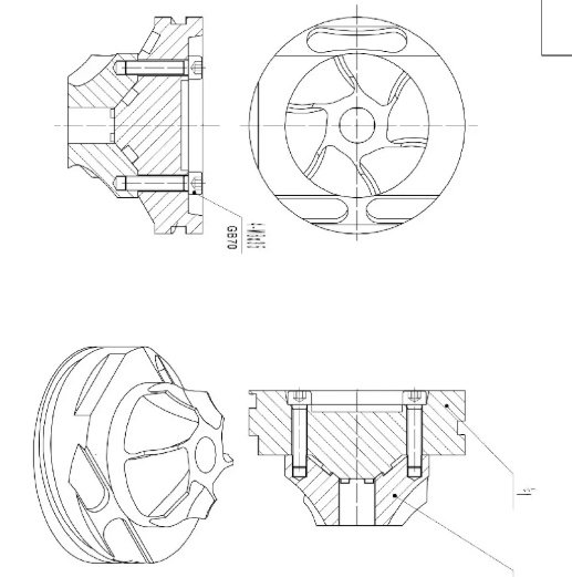
Indexed 5-axis is well suited for prismatic parts with multiple faces and angled features. Simultaneous 5-axis is advantageous for freeform surfaces, continuous blends, and complex geometries such as impellers and turbine blades. When designing parts, identify which areas truly require simultaneous 5-axis toolpaths and which can be produced with indexed positioning to control cost and programming complexity.
Implications for Design and Fixturing
Because the part can be oriented in many ways, the design should consider:
- How the part will be clamped and reoriented
- Where stable datums and reference faces will be located
- Tool reach when the part is tilted or rotated
Complex multi-axis motion does not eliminate the need for good fixturing and clear datum structures. Designs that provide stable reference surfaces and ample clamping zones are more likely to achieve repeatability and dimensional consistency.
Designing for Tool Access and Reach
Even with five axes of motion, tool access remains a dominant factor in manufacturability. Many 3-axis constraints are relaxed but not removed; instead, they are replaced by different constraints related to tool reach, collision risk, and machine kinematics.
Line-of-Sight and Approach Angles
Design every feature with at least one realistic tool approach in mind. Key considerations include:
Preferred approach directions: Whenever possible, orient key features so they can be machined with near-normal tool approach, keeping the cutting tool axis close to perpendicular to the surface. This improves surface quality and reduces deflection.
Minimum access angles: Many machines have tilt limits, commonly in the range of ±110° from vertical for a swiveling head, or similar constraints for trunnion-style tables. For deep or side features, ensure that the necessary tool tilt angles are within typical machine limits.
Avoid blocked line-of-sight: Overhanging flanges, tall bosses, and deep pockets can block tool access to adjacent features. Reposition or modify these features to ensure the cutter can enter and exit without collision.
Tool Length, Deflection, and Aspect Ratio
Tool reach is a central constraint for 5-axis machining. Very long tools increase deflection, reduce stiffness, and may force slower cutting parameters.
General guidelines for aspect ratio (stick-out length divided by tool diameter):
- Preferred: ≤ 5:1 for roughing and general finishing
- Acceptable with care: 8:1 to 10:1 for finishing light cuts
- Beyond 10:1: high deflection risk, usually unsuitable for accuracy-critical surfaces
Design pockets, cavities, and deep features so that standard tools with reasonable aspect ratios can reach the bottom and sides. When possible, increase tool access by:
- Increasing top openings of pockets
- Reducing pocket depth
- Adding reliefs or cutouts to shorten required tool length
Collision Avoidance and Clearance
In 5-axis machining, collisions can occur between the tool holder, spindle head, part, and fixturing. Design to minimize collision risk by providing:
- Adequate radial clearance around deep features for tool holders
- Chamfered or filleted transitions that allow smoother tool orientation changes
- Enough distance between tall neighboring features so the spindle head can tilt and rotate
Where possible, avoid features that require the tool to pass through narrow "tunnel" geometries or enclosed cavities without a clear exit path. If such features are unavoidable, consider whether they can be split into separate components or redesigned for assembly.
Part Orientation, Datums, and Fixturing Surfaces
Because 5-axis machining reduces the number of setups, the initial design must support stable part orientation, accurate datums, and secure fixturing from multiple sides.
Datum Strategy for 5-Axis Parts
A robust datum structure simplifies CAM programming, inspection, and rework. Consider the following practices:
- Define a primary datum plane that will correspond to a stable mounting surface
- Select secondary and tertiary datums that are accessible in all critical orientations
- Use functional surfaces as datums only if they can be protected from clamping damage
For complex freeform parts, dedicated datum features, such as pads, bosses, or machined flats, can provide better repeatability than using curved surfaces as references.
Designing Clamping and Support Features
Clamping points must remain accessible as the part is rotated. Recommendations include:
- Include non-critical pads or tabs specifically for clamping and support
- Avoid placing delicate or tolerance-critical features near clamping zones
- Provide enough material thickness at clamping areas to prevent distortion
For parts that require multiple orientations, consider standardized clamping patterns, such as bolt circles or locating dowel holes, that can be referenced in different setups or machines. These can also serve as inspection datums.
Using Stock Allowances and Holding Tabs
In some cases, extra material must be left for clamping or to maintain rigidity during intermediate machining stages. Common approaches include:
- External stock margins around the part outline
- Temporary ribs or webs for stiffness
- Break-off or machine-off tabs used to hold the part to a base plate
Design these features so they can be easily removed and finished without affecting functional surfaces. Specify where and how much material should be left for such purposes when communicating with the manufacturing team.
Geometry Guidelines for 5-Axis Machined Features
5-axis machining supports complex geometries but still benefits from deliberate, machining-aware design choices. Many geometric details directly affect toolpath strategies, cycle times, and achievable accuracy.
Minimum Wall Thickness and Rib Design
Thin walls and ribs are more prone to vibration, deflection, and distortion during machining. Consider the following numeric guidelines, depending on material and part size:
- Aluminum alloys: typical minimum wall thickness 1.0–1.5 mm for localized features; 2.0–3.0 mm for larger panels
- Steel and stainless steel: typical minimum wall thickness 1.5–2.0 mm for localized features; 3.0–4.0 mm for larger areas
- Titanium and high-strength alloys: typical minimum wall thickness 2.0–3.0 mm or more where stiffness is critical
For ribs and webs, use tapered thickness or add fillets at intersections to increase stiffness. Maintain consistent thickness along ribs to avoid sudden stiffness changes that can cause chatter or localized distortion.
Pocket Design, Corners, and Fillet Radii
Pockets benefit from well-chosen corner radii and adequate tool access. Practical guidelines:
- Internal radii: design corners with radii at least 1.5× to 2× the end mill radius you expect to use, or 3× tool radius if high-speed machining strategies are planned
- Bottom corners: add fillets where possible to reduce stress concentrations and improve toolpath smoothness
- Sharp inside corners: expect that true sharp internal corners cannot be milled; they require EDM, inserts, or redesign
Use consistent radii across similar features to minimize tool changes and simplify programming. For deep pockets, consider stepped depths or intermediate shoulders to maintain stiffness and provide relief for the tool holder.
Holes, Threads, and Cross-Drilled Features
5-axis machining allows easy access to holes at various angles, reducing the need for complex fixtures. When designing holes and threads:
- Standard diameters: follow common drill and tap sizes to use standard tooling
- Minimum thread engagement: commonly 1–1.5× nominal diameter for most metals, depending on load conditions
- Blind holes: provide clearance at the bottom (e.g., 1–1.5× pitch) to accommodate taps and drill tips
For intersecting or cross-drilled holes, ensure that the intersection is accessible for tool entry. 5-axis motion can position the tool at optimal angles, but sufficient clearance is required to avoid collisions.
Freeform Surfaces and Blends
Simultaneous 5-axis machining excels at generating freeform surfaces, but certain practices improve consistency and surface finish:
- Maintain smooth curvature transitions with continuous tangency (G2 continuity) at blends
- Avoid abrupt curvature changes and small, unnecessary surface patches
- Minimize micro-faceting in CAD models; use high-quality spline or NURBS surfaces
Where possible, use consistent surface parameterization and avoid overlapping or self-intersecting surfaces. Well-structured surface geometry leads to more stable toolpaths and predictable surface finish.
Tolerances, Surface Finish, and GD&T for 5-Axis Parts
5-axis machining can achieve tight tolerances and fine surface finishes, but these capabilities depend on machine condition, tooling, and setup. Tolerance and finish specifications should balance functional requirements with realistic machining capability.
Linear and Dimensional Tolerances
Typical achievable tolerances for precision 5-axis machining under controlled conditions might include:
- General dimensional tolerance: ±0.05 mm for standard features
- Tighter features: ±0.01–0.02 mm on localized critical dimensions
- Very high precision features: down to ±0.005 mm in optimized conditions with stable setups
Specify tight tolerances only where functionally necessary. Over-tolerancing non-critical features increases machining time and inspection complexity. Group high-precision features near stable datums when possible to reduce accumulated uncertainty.
Geometric Tolerances on Multi-Axis Surfaces
Geometric Dimensioning and Tolerancing (GD&T) is particularly important for 5-axis parts that feature multiple angled surfaces and freeform geometries. Common controls include:
- Profile of a surface: for freeform or sculpted surfaces
- Position: for holes and pins referenced to angled datums
- Runout or total runout: for rotating components and shafts
- Flatness, perpendicularity, and angularity: for faces that interact with other components
When specifying surface profile on freeform areas, choose values consistent with the intended manufacturing strategy. Typical profile tolerances might range from 0.05–0.2 mm for general freeform surfaces, and 0.01–0.03 mm for high-precision aerodynamic or sealing surfaces, depending on the application and material.
Surface Roughness and Finishing Strategies
Surface roughness is influenced by toolpath type, step-over, tool geometry, and material. Typical ranges achievable in 5-axis machining:
- General machined surfaces: Ra 1.6–3.2 µm
- Fine-finished surfaces: Ra 0.4–0.8 µm with optimized finishing passes
- Very fine surfaces: Ra ≤ 0.2 µm with special strategies and tooling, sometimes combined with post-processing
Specify roughness values consistent with functional needs such as sealing, friction, or aerodynamic performance. For freeform surfaces, step-over and step-down values in the toolpath will be selected to meet these roughness targets and must be compatible with available machining time.
Material Considerations in 5-Axis Machining
Material selection affects allowable wall thickness, tool choice, cutting parameters, and overall machining strategy. Each material class brings specific constraints and opportunities.
Aluminum Alloys
Aluminum is commonly used for 5-axis machined parts due to its machinability and favorable strength-to-weight ratio. Design considerations include:
- Good suitability for thin walls and complex pockets, provided sufficient support is maintained
- Ability to use larger step-overs and higher cutting speeds, reducing cycle time
- Potential for burr formation on thin edges; design edges and chamfers to assist deburring
When designing intricate components, ensure that small features are not weakened by aggressive material removal patterns, particularly where load paths are critical.
Steels and Stainless Steels
Steels and stainless steels require more robust geometries and more conservative design for machinability:
- Use thicker walls and ribs to avoid vibration
- Avoid extremely deep pockets unless absolutely necessary
- For hard or work-hardening grades, design for consistent chip load and avoid interrupted cuts where possible
Allowance for heat-treated conditions should be considered. Features that are difficult to machine after hardening may be designed to be finished in a softer state with subsequent heat treatment, provided dimensional stability needs are addressed.
Titanium and High-Strength Alloys
Titanium and high-strength alloys are common in aerospace and high-performance applications. They are more demanding to machine and require design accommodations:
- Limit extremely thin structures; prioritize stiffness and gradual thickness transitions
- Avoid narrow, deep pockets that trap heat and chips
- Allow for efficient chip evacuation by providing open access and generous corner radii
Due to reduced allowable cutting speeds and higher cutting forces, complex geometry should be evaluated carefully to ensure that tool loads remain manageable.
Designing Freeform and Complex Surfaces for 5-Axis
5-axis machining is often selected specifically for parts with complex freeform surfaces. To obtain stable, accurate results, the underlying CAD geometry must be well structured.
CAD Model Quality and Continuity
High-quality freeform surfaces should exhibit:
- Continuous tangency between adjacent surfaces where a smooth transition is required
- Minimal use of tiny surface patches that complicate toolpath calculation
- Absence of gaps, overlaps, and self-intersections
Use diagnostic tools in CAD to check for continuity and surface quality, especially in areas that will be machined with simultaneous 5-axis strategies.
Controlling Surface Transitions and Blends
Functional performance often depends on smooth transitions between surfaces, such as in aerodynamic or fluid flow applications. From a machining standpoint:
- Large, smooth blends support consistent tool engagement
- Sudden changes in curvature may require slower feeds or smaller step-overs
- Well-defined blend regions help CAM systems generate predictable toolpaths
Where possible, unify adjacent surfaces into single, continuous patches when they are intended to behave as one functional surface. This can avoid visible toolpath boundaries and inconsistent finishes.
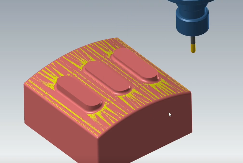
Step-Over, Toolpath Density, and Machining Time
For freeform finishing, the choice of step-over, toolpath pattern, and tool orientation is directly related to surface quality and cycle time. In design, anticipate that:
- Smaller step-over improves surface roughness but increases machining time
- Complex curvature may require adaptive step-over to maintain consistent scallop height
- Stable tool orientation reduces surface variation and feedrate fluctuations
While these parameters are set in CAM, designers should be aware that overly intricate surface details or unnecessary small-scale undulations can significantly increase machining time without functional benefit.
Feature Consolidation and Part Integration
5-axis machining allows multiple features to be manufactured in a single setup, enabling consolidation of parts and reduction of assembly steps. However, integration must be balanced with manufacturing and inspection considerations.
When to Integrate Versus Split Parts
Consider integrating parts when:
- Multiple components can be machined from a single block without creating unmachinable regions
- Tolerances between previously separate parts are tight and hard to maintain in assembly
- Assembly complexity outweighs the additional material and machining cost
Conversely, maintain separate parts when:
- Integrated geometry creates deep, enclosed features that are difficult to machine
- Different materials or heat treatments are required in different regions
- Maintenance or replacement of specific components is important in service
Modular Design for Machinability
Modular design can combine the advantages of part consolidation with practical manufacturability. For example:
- Primary structural module with easily machined shapes
- Secondary modules for extremely fine or localized features
- Attach points designed for precise dowel and bolt interfaces
Ensure that joining features (bolted, pinned, or otherwise) are accessible by tools and inspection probes when the assembly is partially or fully assembled.
CAM-Focused Design Considerations
Successful 5-axis machining depends heavily on CAM programming. Design choices can make toolpath generation simpler and more robust, or they can complicate programming significantly.
Consistent Feature Families and Tool Reuse
Grouping features into consistent families enables reuse of tooling and machining strategies. For example:
- Use consistent hole diameters and depths across a part where feasible
- Standardize fillet radii and chamfers
- Align similar features to share approach vectors and tool orientations
This reduces the number of tools required, simplifies CAM setups, and can reduce changeover time on the machine.
Avoiding Unnecessary Complexity in Surfaces
Extra curvature or decorative features that do not contribute to functionality can create unnecessary complexity in the CAM workflow. Wherever possible:
- Keep surfaces simple and functional
- Limit small-scale undulations or cosmetic features that force finer toolpaths
- Use planar or simple surfaces where complex freeform shapes are not required
Such simplifications can significantly reduce programming and machining time without compromising performance.
Safe Zones and Toolpath Transitions
During 5-axis machining, rapid moves and transitions between orientations must be safe and collision-free. Design can assist by:
- Providing open areas around critical surfaces where the tool can retract and reposition
- Avoiding narrow corridors that force long, constrained repositioning moves
- Including reference surfaces that can be used for intermediate clearance moves
When parts include both intricate and open areas, designers can exploit the open regions as safe zones for entry, exit, and orientation changes.
Inspection, Metrology, and Feedback into Design
Inspection of 5-axis machined parts is often performed on multi-axis CMMs or using scanning systems. Design should facilitate reliable metrology and feedback.
Datum Targets and Inspection Features
To ensure consistent inspection, define clear datum targets that correspond to stable surfaces or features on the part. Consider:
- Dedicated inspection pads or bosses located near critical geometry
- Accessible probe paths for CMMs for all toleranced surfaces
- Use of alignment features compatible with in-machine probing where applicable
These features should be robust, non-critical to function, and easy to access without obstructing other measurements.
Design for In-Process Verification
5-axis machines frequently employ in-process probing to verify critical dimensions and adjust toolpaths. Designers can support this by:
- Including flat or spherical reference features suitable for probing
- Ensuring that critical features are reachable by the probe at key stages of machining
- Allowing space for probe access without interfering with fixturing
In-process verification can reduce scrap rates and provide data for refining future design iterations.
Feedback Loops from Manufacturing to Design
Consistent feedback from machining and inspection to design teams allows continuous improvement. Typical feedback items include:
- Locations where tool access is marginal or collision-prone
- Features that require excessive tool changes or special tooling
- Tolerance areas that drive disproportionate cost or scrap
Incorporating this feedback into subsequent design revisions leads to parts that are more robust, easier to machine, and more economical to produce.
Common Pain Points and How Design Can Address Them
While 5-axis machining unlocks high flexibility, certain recurring issues often arise during production. Many of these can be mitigated through appropriate design choices.
Excessive Setup and Programming Time
Complex parts with inconsistent feature standards, unnecessary surface complexity, or unclear datum structures often require extended CAM and setup time. To address this in design:
- Standardize features (hole sizes, radii, chamfers) where possible
- Provide explicit datums aligned with real-world fixturing strategies
- Minimize cosmetic features that require fine freeform toolpaths
These steps help reduce lead time and make the part more scalable for repeated production.
Chatter, Vibration, and Dimensional Instability
Thin sections and long, unsupported spans are prone to vibration and deflection during machining, leading to poor surface finish and dimensional deviation. Design mitigations include:
- Increase wall thickness or add ribs in regions prone to deflection
- Provide temporary support structures where practical
- Avoid very deep, narrow features that force long tool overhang
Where thin walls are functionally necessary, coordinate with manufacturing to plan machining sequences that maintain support as long as possible during roughing and semi-finishing.
Collision Risks and Limited Tool Orientation Space
Dense collections of tall features or closely spaced protrusions can make it difficult to orient the tool without collision. To reduce these risks:
- Increase spacing between tall features where feasible
- Reduce unnecessary height in non-critical bosses
- Provide chamfers or cutaways that increase angular access
These changes can significantly improve programming flexibility and reduce the likelihood of collisions during complex toolpaths.
Practical Parameter Ranges for 5-Axis Design
The following table summarizes some typical design-related parameter ranges that are commonly achievable in 5-axis machining across many applications. These values are indicative and depend on machine capability, tooling, material, and process control.
| Parameter | Common Range | Notes |
|---|---|---|
| General dimensional tolerance | ±0.05 mm | Standard features, moderate precision |
| Precision dimensional tolerance | ±0.01–0.02 mm | Critical features with stable setups |
| Surface profile on freeform surfaces | 0.01–0.2 mm | Depends on functional requirements |
| Surface roughness, general | Ra 1.6–3.2 µm | Standard finishing passes |
| Surface roughness, fine | Ra 0.4–0.8 µm | Refined finishing strategies |
| Tool aspect ratio (L/D) | ≤5:1 preferred, up to 8–10:1 with care | Higher ratios increase deflection risk |
| Internal corner radius | ≥1.5–2× tool radius | Larger radii improve tool life and flow |
| Minimum wall thickness (aluminum) | 1.0–1.5 mm (local), 2.0–3.0 mm (larger) | Depends on size and loading |
| Minimum wall thickness (steel) | 1.5–2.0 mm (local), 3.0–4.0 mm (larger) | Requires robust fixturing |
| Minimum wall thickness (titanium) | 2.0–3.0 mm or more | Higher stiffness recommended |
Design Collaboration and Data Handoff
Good design for 5-axis machining depends not only on geometry but also on how information is communicated between design and manufacturing teams.
Model-Based Definition (MBD) and PMI
Model-based definition uses annotated 3D models as the primary source of product definition, including dimensions, tolerances, and notes. For 5-axis parts, this approach can:
- Clarify relationships between complex surfaces and datums
- Reduce ambiguity compared to 2D drawings for angled and freeform features
- Enable direct consumption of PMI by CAM and CMM software
When using MBD, ensure that annotations are organized logically, fully define the part, and clearly indicate datums and feature control frames.
Providing Manufacturing Notes and Intent
Beyond tolerances and geometry, communicate design intent, including:
- Which surfaces are functionally critical versus cosmetic
- Preferred or prohibited part orientations for specific features
- Surfaces that can remain unfinished or rougher than others
Such information allows manufacturing teams to prioritize operations and optimize strategies for the most important features.
Version Control and Change Management
Because 5-axis machined parts often involve substantial CAM programming effort, design changes must be controlled carefully. Effective practices include:
- Clear revision identifiers in model and drawing files
- Change descriptions focused on features that affect machining
- Coordination between design and CAM teams before implementing major geometry alterations
This helps avoid mismatches between CAD, CAM, and shop-floor programs, reducing the risk of incorrect parts being produced.
Summary of Key 5-Axis Design Principles
Effective design for 5-axis machining requires an integrated view of part geometry, machine capabilities, tooling, fixturing, and inspection. Key principles include:
- Design with tool access and realistic tool aspect ratios in mind
- Establish stable datums and fixturing features accessible in multiple orientations
- Use consistent feature families to simplify tooling and programming
- Apply tolerances and surface finish requirements selectively, based on functional needs
- Ensure CAD models, especially freeform surfaces, are clean, continuous, and machining-aware
- Plan for inspection and in-process verification when defining features and datums
By incorporating these guidelines early in the design process, engineers can reduce manufacturing risk, shorten lead times, and obtain more reliable outcomes from 5-axis CNC machining.
FAQ: 5-Axis Machining Design Guidelines
What is the main design advantage of 5-axis machining over 3-axis machining?
The main design advantage of 5-axis machining is the ability to reach multiple faces and complex surfaces in a single setup. This reduces the need for multiple fixtures and repositioning, enabling tighter relative tolerances between features and allowing more complex geometries, such as freeform surfaces and angled holes, to be machined efficiently. It also allows optimal tool orientation relative to the surface, improving surface finish and tool life.
How tight can tolerances realistically be for 5-axis machined parts?
Realistic tolerances for 5-axis machined parts depend on material, part size, machine condition, and fixturing quality. As a general guideline, ±0.05 mm is common for general dimensions, ±0.01–0.02 mm is achievable for localized critical dimensions, and around ±0.005 mm is possible in optimized conditions for specific features. For freeform surfaces, surface profile tolerances of 0.01–0.03 mm are typically attainable on critical areas. It is best to specify tight tolerances only where they are functionally necessary.
Do all features need simultaneous 5-axis machining?
No. Many features can be machined with indexed 5-axis (3+2) operations, where the part is rotated into position and then machined using 3-axis toolpaths. Simultaneous 5-axis machining is most beneficial for freeform surfaces, continuous blends, impellers, blisks, and similarly complex geometries. Using indexed 5-axis for prismatic features and reserving simultaneous 5-axis for areas where it is truly needed helps control cost and simplify programming.
How should I choose corner radii and fillets for 5-axis machining?
Corner radii and fillets should be chosen to match realistic tool sizes and to support smooth toolpaths. A useful rule of thumb is to design internal corner radii at least 1.5–2 times the end mill radius you expect to use, or larger for high-speed machining. Consistent radii across similar features reduce tool changes and simplify CAM programming. Generous fillets at pocket bottoms and feature intersections also reduce stress concentrations and improve surface quality.
