
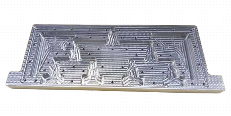
CNC machining almost always leaves some form of visible or measurable mark on a part’s surface. These marks are a direct result of the cutting process and include tool paths, feed lines, burrs, and other surface features. Whether these marks are acceptable depends on the functional and aesthetic requirements of the component.
This article explains why CNC machining leaves marks, the typical types of marks, how they relate to surface roughness and dimensional accuracy, how to control or remove them, and how to specify requirements clearly when ordering CNC parts.
Why CNC Machining Leaves Marks
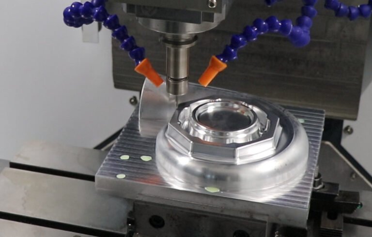
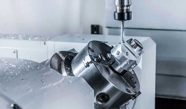
CNC machining removes material using a rotating or reciprocating tool. Each cutting edge interacts with the workpiece, producing a characteristic pattern. These patterns are influenced by tool geometry, material properties, feed rate, spindle speed, and machine rigidity.
Material Removal Mechanism
During machining, material is removed as chips. The tool does not cut continuously along an ideal elastic line; instead, microscopic vibrations, tool deflection, and chip formation create irregularities. Even in highly optimized conditions, the surface is made up of fine peaks and valleys known as surface texture.
Key factors that inherently generate marks include:
- Discrete cutting edges on milling cutters and drills
- Relative motion of tool and workpiece (feed direction and speed)
- Elastic deformation of the workpiece and tool under cutting forces
- Chip formation and evacuation behavior
Relationship Between Cutting Parameters and Marks
Feed per tooth, spindle speed, and tool diameter have a direct impact on visible machining marks. A larger feed per revolution or per tooth generally produces deeper and more pronounced tool paths, while higher spindle speeds can reduce mark amplitude but may induce other issues if not balanced with feed and tool rigidity.
Typical relationships include:
- Higher feed rate → larger scallop height → more visible lines
- Smaller step-over in milling → finer pattern → better surface finish
- Higher spindle speed (within limits) → more overlapping cuts → smoother appearance
Because these relationships are predictable, machinists can tune the process to minimize marks when required, at the cost of longer cycle times or more complex toolpaths.
Common Types of CNC Machining Marks
Surface marks from CNC machining vary in appearance and cause. Recognizing them helps in diagnosing process issues and selecting appropriate finishing techniques.
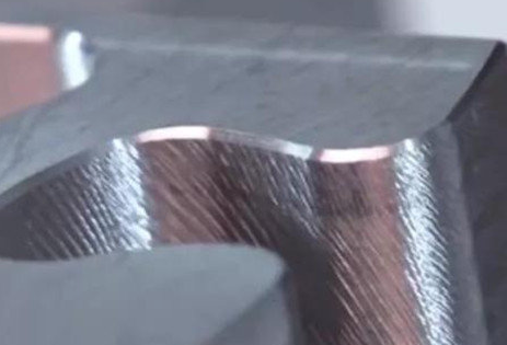
Tool Path or Tooling Marks
Tool path marks are directional patterns that follow the movement of the cutter. On milled surfaces, they usually appear as parallel or overlapping curves or lines. On turned parts, they manifest as concentric rings around the axis of rotation.
Typical characteristics:
- Regular spacing corresponding to feed per revolution or per tooth
- Consistent orientation matching tool motion (linear or circular)
- Amplitude directly linked to scallop height and tool radius
These marks are not necessarily defects; they are often acceptable in functional surfaces where aesthetics are not critical, provided the surface roughness meets specification.
Burrs
Burrs are small, unwanted projections of material along edges or at the exit of holes. They arise when the material is plastically deformed rather than cleanly sheared. Burrs are common in metals with good ductility and at cutting conditions that do not fully fracture the chip at the boundary.
Main types of burrs from CNC machining include:
- Exit burrs on drilled or milled holes
- Edge burrs along profiles or slot edges
- Corner burrs at intersections of machined surfaces
Burrs are generally unacceptable for functional, assembly, or safety-critical surfaces because they can cut operators, interfere with assembly, and break off to become contamination.
Chatter Marks
Chatter marks are periodic, wave-like patterns caused by self-excited vibrations of the tool or workpiece. They are often easily visible and can compromise both appearance and fatigue performance.
Common indicators of chatter:
- Repeating ripples with consistent spacing along the feed direction
- Distinctive noise during machining
- Surface roughness significantly higher than expected from programmed parameters
Chatter often indicates insufficient rigidity, incorrect cutting parameters, or inadequate workholding.
Tool Wear Marks and Built-Up Edge (BUE)
Tool wear changes the effective shape and sharpness of the cutting edge over time. A worn tool can create burnished areas, micro-cracks, or irregular tool marks. Built-up edge, where material welds to the cutting edge, can cause intermittent gouging and inconsistent finish until the built-up material breaks away.
Typical symptoms:
- Random scratches or grooves along the feed direction
- Discoloration due to overheating
- Localized roughness while other areas look acceptable
Step Marks and Blend Lines
In 3D milling or when switching between tools or setups, step marks and blend lines can appear where toolpaths or fixturing change. These are especially common on freeform surfaces and large contoured components.
Characteristics:
- Visible “stairs” on sloped or contoured surfaces due to finite step-over
- Transitions where one tool or operation meets another
- Minor misalignment from repositioning or refixturing
Surface Roughness and How It Relates to Marks
Surface marks can be quantified using surface roughness metrics rather than evaluated purely visually. The most common parameter is Ra (arithmetical mean roughness), but other parameters such as Rz are also used.
| Process / Condition | Typical Ra (µm) | Typical Application |
|---|---|---|
| General-purpose milling (no special finish requirement) | 1.6 – 3.2 | Structural parts, non-cosmetic surfaces |
| Finish milling / turning with optimized parameters | 0.4 – 1.6 | Functional surfaces, improved aesthetics |
| Fine turning, fine boring | 0.2 – 0.8 | Bearing surfaces, sealing faces (with further treatment if needed) |
| Grinding or polishing after machining | 0.05 – 0.2 | Precision fits, high aesthetic surfaces |
Lower Ra values correspond to smoother surfaces and less pronounced tool marks. However, two surfaces with the same Ra can look different if the pattern and direction of marks differ, so both numerical roughness and visual requirements may need to be specified.
Directionality of Marks
Surface roughness is often anisotropic: its characteristics depend on direction. For example, turned shafts have circular tool marks that can affect sealing and wear differently along and across the axis. In sealing or sliding applications, the direction of machining marks relative to motion or fluid flow can be critical.
Specifying Surface Finish in Drawings
Engineering drawings often specify surface finish using standardized symbols and numerical values (for example, Ra 1.6 µm maximum). When tolerancing surface finish for CNC machined parts, consider:
- The function of the surface (sliding, sealing, cosmetic, structural)
- Manufacturability and cost impact of very low Ra values
- The need for direction control (e.g., crosshatch vs. unidirectional marks)
Influence of Material on Machining Marks
Different materials respond differently to cutting forces, heat, and tool geometry, which changes the character and severity of machining marks.
Metals
Metallic materials show a wide range of surface responses:
Aluminum alloys: Generally easy to machine and capable of fine surface finishes. However, aluminum is prone to built-up edge, which can create sporadic marks and localized roughness. Cutting tools with appropriate coatings and high positive rake angles help minimize marking.
Carbon and alloy steels: Machinability varies widely. At moderate hardness, steels can produce clean finishes; at higher hardness, tool wear and chatter become more significant factors in surface quality. Heat generation and microstructural variations can influence mark uniformity.
Stainless steels: Work hardening and poor thermal conductivity can lead to higher cutting temperatures and tool wear, increasing the risk of tool marks, chatter, and built-up edge. Optimized cooling and cutting strategies are important to control surface marks.
Copper and copper alloys: Ductility and tendency to smear can cause burrs and smeared tool marks. Sharp tools and careful control of feed and speed are necessary for clean finishes.
Plastics
Many plastics are softer and less rigid than metals, making them more sensitive to deformation and melting. Marks on plastic parts may include:
- Smearing and tearing instead of clean cutting
- Melting and re-solidified surface irregularities at high cutting temperatures
- Residual stresses that become visible after machining
Lower cutting speeds, sharp tools with high rake, and appropriate chip evacuation are important to minimize marks on plastic components.
Composite Materials
Fiber-reinforced composites can exhibit:
- Fiber pull-out and broken fibers at the surface
- Matrix cracking next to the machined area
- Delamination at edges and drilled holes
These features may appear as rough, frayed edges or irregular surface patterns. Specialized tooling and machining strategies are often required to control surface integrity and appearance.
How CNC Process Parameters Affect Marks
Process parameters are the primary levers for controlling the visibility and severity of machining marks. Adjusting them can often improve finish without changing the fundamental machining process.
Feed Rate and Step-Over
Feed rate directly impacts the spacing and height of machining marks:
- Higher feed → larger scallops and more visible lines
- Lower feed → reduced scallop height and smoother appearance but longer cycle time
Step-over (in milling) determines how much the cutter overlaps with its previous pass. Smaller step-over values reduce step marks on contoured surfaces and improve visual uniformity.
Spindle Speed
Spindle speed affects cutting temperature, chip load per tooth, and tool vibration characteristics. Within a practical range:
- Higher speed at constant feed reduces feed per revolution, often improving finish
- Too high a speed can cause overheating, accelerated wear, or chatter
Balancing spindle speed and feed to maintain favorable chip load is essential.
Depth of Cut
Depth of cut influences cutting forces and tool deflection. Excessive depth of cut can cause:
- Increased chatter and vibration marks
- More pronounced deflection leading to uneven tool engagement
For finishing passes, smaller depth of cut is typically used to reduce marks and achieve tighter tolerances.
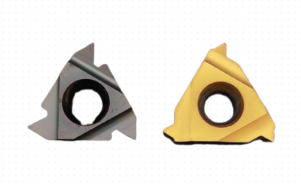
Tool Geometry and Tool Condition
Tool material, coating, rake angle, nose radius, and edge preparation all have a substantial effect on the surface. A larger nose radius at the tool tip in turning can reduce Ra, because it generates a smoother profile between successive tool passes, but may increase radial cutting forces.
Tool condition is critical. A sharp, unworn tool produces more consistent and shallow tool marks. As the tool wears, its effective geometry changes, and surface finish degrades with increased roughness, random scratches, and potential thermal damage.
Pain Points: When Machining Marks Become a Problem
Not all machining marks are simply aesthetic issues. In many applications, visible marks correspond to technical or operational problems that must be resolved.
Functional Interference and Fit
Raised tool marks and burrs can interfere with tight fits, sliding surfaces, and sealing interfaces. For example, a precision shaft with excessive turning marks may not achieve the required bearing life or sealing performance. Marks that exceed tolerance can alter effective dimensions and cause assembly or performance issues.
Fatigue and Stress Concentration
Deep tool marks or chatter marks act as localized notches and can serve as stress risers. In cyclically loaded components, these features can reduce fatigue life and lead to early crack initiation. This is particularly relevant in aerospace, automotive, and structural components exposed to high stress.
Contamination and Cleanliness
Burrs and loose particles generated by poor surface control can detach, leading to contamination in hydraulic systems, medical devices, or cleanroom environments. These small fragments may obstruct fluid paths, damage sensitive components, or compromise sterility.
Cosmetic and Branding Requirements
Products with visible machined surfaces often have strict aesthetic requirements. In such cases, consistent and low-visibility machining marks are a requirement rather than a preference. Random scratches, visible tool change blend lines, or inconsistent textures can be unacceptable on consumer-facing products, instrumentation housings, and high-end equipment.
Methods to Minimize or Remove CNC Machining Marks
Although machining marks are inherent to cutting processes, their visibility and impact can be significantly reduced through process optimization and post-processing. The choice of method depends on geometric complexity, material, functional requirements, and cost constraints.
Process Optimization During Machining
Before resorting to secondary finishing operations, CNC parameters can often be tuned to improve finish:
- Use specialized finishing passes with reduced feed and depth of cut
- Optimize tool paths to maintain consistent cutter engagement and reduce tool load variation
- Increase step-over resolution for 3D surfaces where smoother contours are required
- Select tool geometries designed for finishing (fine pitch, polished flutes, suitable coatings)
- Improve workholding rigidity to reduce vibration and chatter
Deburring
Deburring is the primary method to remove burrs and sharp edges resulting from machining. Techniques include:
- Manual deburring with files, scrapers, and abrasive tools
- Mechanical deburring (barrel tumbling, vibratory finishing, abrasive brushing)
- Thermal deburring (using controlled explosions in a chamber)
- Electrochemical deburring for specific internal features
Deburring focuses mainly on edges and does not necessarily alter the bulk surface texture; it addresses safety, assembly, and cleanliness rather than general tool marks.
Polishing and Grinding
Polishing and grinding can significantly reduce or remove visible machining marks and achieve very low roughness values. They are especially common for precision fits, sealing surfaces, and high-quality optical or decorative finishes.
Typical approaches:
- Surface grinding for flat surfaces with tight flatness and finish requirements
- Cylindrical grinding for shafts and bores requiring high accuracy and smoothness
- Hand or machine polishing with progressively finer abrasives
These processes can be more time-consuming and require specialized equipment, so they are usually reserved for critical surfaces.
Blasting (Bead Blasting, Sandblasting)
Blasting processes use streams of abrasive media to modify the surface. Bead blasting, in particular, is common after CNC machining for improving appearance and creating a uniform matte texture that masks subtle tool marks.
Variables in blasting include media type (glass beads, aluminum oxide, etc.), media size, pressure, and exposure time. Blasting can unify surface appearance but may not fully remove deep defects or marks.
Chemical and Electrochemical Treatments
Chemical polishing, electropolishing, and etching can smooth microscopic peaks and valleys, reduce surface roughness, and improve corrosion resistance for certain metals. These processes attack the material electrochemically or chemically, slightly dissolving high points on the surface.
They are particularly useful for complex geometries where mechanical finishing cannot reach all areas, such as internal channels or intricate medical devices.
Coatings and Surface Conversion Processes
Coatings and conversion layers cannot fully hide deep marks, but they can modify visual appearance and, in some cases, slightly smooth the surface. Examples include:
- Anodizing for aluminum, which can accentuate or soften existing textures depending on the finish type
- Plating (nickel, chrome, etc.), which can fill minor surface irregularities while adding functional properties
- Painting or powder coating, which visually hides fine marks but may telegraph deeper defects
These methods are usually applied for corrosion resistance, wear resistance, or aesthetics, with the side effect of altering the visual perception of machining marks.
Specifying Acceptable Marks and Finishes in CNC Orders
When ordering CNC machining services, it is important to clearly define what level of marks is acceptable. Overly vague requirements can lead to parts that technically meet dimensions but fail cosmetically or functionally, while excessively strict requirements can drive up costs unnecessarily.
Defining Surface Finish Requirements
Consider specifying:
- Surface roughness values (e.g., Ra ≤ 1.6 µm) for functional surfaces
- Areas that require specific finishing (e.g., sealing faces vs. non-critical surfaces)
- Allowed or prohibited finishing processes (e.g., no blasting inside fluid passages)
- Visual standards or references for cosmetic surfaces (sample parts, photos)
Explicitly identifying “critical surfaces” ensures that time and cost are focused where they matter most.
Geometric Tolerances and Edge Conditions
In addition to surface finish, drawings should specify:
- Edge breaks or chamfers to control burrs and sharpness
- Geometric tolerances (flatness, cylindricity, etc.) which may be affected by finishing
- Protected surfaces where no secondary operations are allowed
Clear notes about deburring requirements (e.g., “Remove all burrs and sharp edges; break edges 0.1–0.3 mm”) help avoid misunderstandings about acceptable marks on edges.
Cost and Time Considerations Related to Machining Marks
Reducing or eliminating visible machining marks typically increases cost and lead time. This is due to slower finishing passes, additional post-processing, more stringent inspection, or a combination of these. Understanding how surface requirements drive cost helps in balancing performance, appearance, and budget.
Cost drivers include:
- Additional machine time for fine toolpaths and low-feed finishing passes
- Manual labor for deburring, polishing, or buffing
- Specialized equipment for grinding, blasting, or electrochemical finishing
- Higher scrap risk when cosmetic or high-precision requirements are strict
Because of these factors, surface specifications should be no more stringent than necessary for the intended application.
Inspection and Quality Control of Machining Marks
Quality control processes confirm that machining marks and surface characteristics remain within specification. Inspection methods range from simple visual checks to detailed metrology.
Visual and Tactile Inspection
Visual examination under suitable lighting is often the first step. It helps identify:
- Obvious tool marks, chatter, or scratches
- Burrs and sharp edges
- Inconsistent textures across a surface
In some cases, users also perform simple tactile checks, running a fingertip or a test strip over the surface to detect raised marks or burrs that might not be immediately visible.
Metrology for Surface Roughness
Surface profilometers (contact or non-contact) measure roughness parameters such as Ra and Rz. Optical methods, including interferometry or confocal microscopy, can provide detailed topographic maps of the surface. These methods quantify mark height and spacing, eliminating subjectivity in deciding whether the finish meets specification.
For critical parts, inspection procedures and acceptance criteria should be documented alongside machining and finishing specifications.
Practical Guidelines for Managing CNC Machining Marks
The presence of machining marks is not inherently problematic. The objective is to control them so that they do not compromise function, safety, or appearance. A practical approach can be summarized as follows:
| Goal | Primary Strategies | Typical Trade-Offs |
|---|---|---|
| Basic functional surface with visible but acceptable marks | Standard machining parameters, general deburring | Lower cost, shorter lead time; visible tool paths |
| Improved aesthetics with reduced marks | Finishing passes, optimized step-over, bead blasting | Additional machine time and secondary processing |
| High-precision surfaces with minimal marks | Fine cutting conditions, grinding or polishing, tight QC | Highest cost and longest lead time |
| Burr-free and safe edges | Defined edge breaks, targeted deburring methods | Extra deburring operations and inspection |
Balancing these strategies according to the part’s functional and visual requirements allows effective management of machining marks without unnecessary cost escalation.
FAQ About CNC Machining Marks
Do all CNC machined parts have visible tool marks?
Nearly all CNC machined parts have some level of tool marks, but their visibility varies widely. With optimized cutting parameters and appropriate finishing processes, marks can be minimized to the point where they are barely visible or only detectable under magnification or with tactile inspection. For many industrial applications, the marks produced by a standard finishing pass are acceptable. For high-end cosmetic or precision surfaces, additional operations such as polishing or bead blasting are used to further reduce or disguise marks.
Can machining marks affect dimensional accuracy or only appearance?
Machining marks can affect both appearance and function. Shallow, uniform tool paths usually have a negligible effect on overall part dimensions and are considered primarily cosmetic. However, deep marks, chatter marks, or burrs can effectively change local dimensions, interfere with fits, act as stress risers, or compromise sealing surfaces. For parts with tight tolerances or critical surfaces, surface finish is specified alongside dimensional tolerances to ensure that machining marks remain within permissible limits.
How can I specify that I don’t want visible machining marks?
To limit visible machining marks, specify quantitative surface roughness values (for example, Ra ≤ 0.8 µm) on drawings for cosmetic or functional surfaces and indicate required post-processing such as bead blasting, polishing, or grinding. It is helpful to identify which surfaces are cosmetic and which are non-critical, and to provide reference samples or images when possible. Clear notes about deburring and edge breaks, as well as any restrictions on processes (such as no blasting inside precision bores), help ensure the final parts match expectations.
Is bead blasting enough to hide all machining marks?
Bead blasting is very effective at unifying surface appearance and reducing the visual prominence of fine tool marks, but it does not remove deeper defects such as heavy chatter, deep scratches, or significant step marks. These deeper features may remain visible through the blasted finish. For parts with such defects, corrective machining, localized grinding, or polishing may be required before blasting to achieve a uniformly smooth and aesthetically pleasing surface.
Do smoother surfaces from CNC machining always cost more?
Achieving smoother surfaces generally increases cost because it requires slower cutting parameters, additional finishing passes, secondary finishing processes, or more extensive inspection. However, modest improvements can sometimes be achieved at low cost by optimizing existing toolpaths and cutting conditions. The largest cost increases typically occur when moving from standard industrial finishes to high-end cosmetic or precision surfaces, especially when polishing, grinding, or extensive manual work is involved.
