
Preparing the correct files is essential for efficient and accurate CNC machining. From the first design sketch to the final part produced on a CNC machine, each step requires specific file types and structured data. This guide explains the files you need, how they relate to each other, and what information each file should contain for a robust CNC workflow.
Core CNC File Categories
Most CNC workflows rely on four major categories of files. In smaller shops one person may handle all of them, while in larger environments different departments own each stage.
- CAD design files
- CAM programming files
- Machine-ready CNC program files (G-code/NC files)
- Supporting documentation and reference data
Understanding how these file categories interact helps prevent missing data, incompatible formats, and production delays.
CAD Files: Design Data for CNC
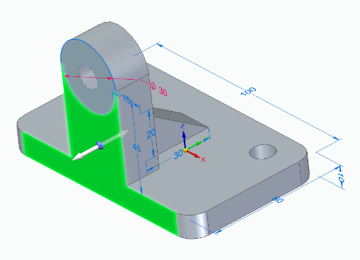
CAD (Computer-Aided Design) files contain the geometric definition of the part. They describe shapes, dimensions, and sometimes product manufacturing information (PMI). These files are typically the first digital assets in a CNC workflow.
Common CAD File Types for CNC
The most frequently used CAD file types for CNC machining include:
| File Type | Extension | Usage in CNC | Key Advantages | Typical Limitations |
|---|---|---|---|---|
| 2D DXF | .dxf | Laser cutting, plasma cutting, waterjet, simple routing, 2D milling | Widely supported, good for contours and profiles | No 3D data, limited tolerance information |
| 2D DWG | .dwg | Similar to DXF; often converted to DXF for CAM | Native to AutoCAD, compact | Not all CAM systems read DWG directly |
| 3D STEP | .step, .stp | General-purpose 3D geometry for milling and turning | Standardized, widely accepted, supports assemblies | Some feature data may be lost in exchange |
| 3D IGES | .iges, .igs | Surface and wireframe models for older or legacy workflows | Broad compatibility | Less robust than STEP, possible geometry gaps |
| 3D Parasolid | .x_t, .x_b | High-quality solids, often for advanced milling | Accurate solid models, strong feature support | Not universal, more common in specific CAD/CAM systems |
| Native CAD (e.g., SolidWorks) | .sldprt, .prt, etc. | Direct import to certain CAM systems for feature-based machining | Maintains design features and parameters | CAM system must support specific CAD format |
2D vs 3D CAD Files for CNC
The files you need depend on the process and the complexity of the part.
- 2D CAD files are typically enough for sheet metal cutting, engraving, simple pockets, and profiles.
- 3D CAD files are strongly recommended for multi-axis milling, complex contours, free-form surfaces, and parts requiring tight fits.
Even when a 3D model is available, many shops still request 2D drawings for dimensions, tolerances, and notes. The 3D model drives CAM toolpaths, while the 2D drawing defines inspection criteria and acceptance requirements.
Critical Information in CAD Files for CNC
For reliable CNC machining, CAD data should be complete and unambiguous. Important aspects include:
Geometric integrity: Surfaces should be watertight, curves should not have breaks, and there should be no duplicates or overlapping entities. This prevents toolpath calculation errors and unexpected tool motion.
Coordinate system and origin: Ideally the model origin and orientation match how the part will be fixtured on the machine, or at least are easy to relate to a practical work coordinate system.
Units and scale: All CAD files should clearly indicate whether metric or imperial units are used. Mismatches cause severe dimensional errors.
Tolerance and GD&T data (usually in 2D drawing or PMI): Critical features require defined tolerances, datums, and surface finish specifications; without them, machinists may default to assumptions that do not match engineering intent.
CAM Files: Toolpaths and Process Data
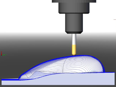
CAM (Computer-Aided Manufacturing) files translate CAD geometry into toolpaths and operations that a CNC machine can execute. These files usually exist inside a CAM software environment and are often proprietary to that system.
CAM Project or Part Files
Most CAM systems use a project, part, or job file that contains:
- Imported CAD geometry (2D or 3D)
- Stock size and shape
- Work coordinate systems
- Tool libraries and selected tools
- Toolpaths for each operation (pocketing, drilling, contouring, finishing, etc.)
- Feeds, speeds, stepovers, depths of cut
- Coolant, tool change, and other machine control parameters
File extensions vary by software (for example .cam, .mcam, .f3d, .prt, .sldcam, and many others). These files are not usually sent to the CNC machine directly. Instead, the CAM system uses them to generate G-code files tailored to each machine and controller.
Tool Libraries and Technology Databases
To streamline programming, many shops maintain separate files or databases for tools and machining parameters. These include:
Tool library files: Lists of tools with IDs, diameters, lengths, corner radii, flute counts, holder information, and tool type (end mill, drill, reamer, etc.). Consistent tool IDs between CAM and CNC machines reduce setup errors.
Cutting data libraries: Material-specific feeds and speeds, stepdowns, stepover values, and recommended strategies for different tool and material combinations.
These libraries may be stored in local files or external databases, and referenced by CAM projects. They are essential for repeatability and process standardization.
Post Processor Configurations
Post processors are configuration files and logic that convert generic CAM toolpaths into controller-specific G-code. Each combination of machine and controller may require its own post processor.
Typical post processor data includes:
Supported codes and syntax: G-code dialect, canned cycles, macro calls, and special functions. Header and footer structure: Program numbering, safety lines, units, plane selection, and end-of-program blocks.
Axis naming and limits: Machine axes, rotary directions, soft limits, and travel ranges. Tool and offset handling: How tool lengths, wear offsets, and work coordinate systems are referenced.
Without a correct post processor file, you may have valid toolpaths but produce G-code that does not run correctly on the actual machine, or fails to use available machine functions efficiently.
G-Code and NC Program Files
G-code, often stored in NC files, is the machine-level program that CNC controllers execute. These files are typically the final output that moves from programming to the CNC machine.
Standard G-Code File Formats
Common extensions for CNC program files include:
.nc, .tap, .gcode, .cnc, .eia, and others defined by shop standards or machine builder defaults.
Though file extensions vary, the contents are generally line-based program blocks containing G-codes, M-codes, coordinates, feedrates, and other instructions.
Contents of a G-Code File
A well-structured CNC program file usually contains:
Program header: Program number or name, part identification, revision, and sometimes material or customer details. Safety setup: Units declaration (G20/G21), absolute or incremental mode (G90/G91), plane selection (G17/G18/G19), and initial tool and spindle states.
Machining operations: Linear and circular motion commands, canned cycles for drilling or tapping, tool changes, feed and speed changes, and work offset calls.
Program end: Spindle stop, coolant off, axis retraction, return to home position, and program end codes.
Machines with advanced capabilities may also use subprograms, macros, probing cycles, and user-defined routines. These also live in G-code files or associated macro program files stored on the controller.
Program Structure and Organization
To keep CNC program files manageable and maintainable, many shops adopt consistent file naming and structure rules:
- Identify the machine or controller type in program naming conventions when needed.
- Use separate files for roughing and finishing operations when files are long or need different setups.
- Keep probing routines, common fixtures, and standard patterns in reusable subprogram files.
This organization helps avoid confusion when multiple versions of a program exist for different machines or setups.
Machine Setup and Fixture Files
Beyond geometry and toolpaths, CNC machining depends heavily on how the part is held and located on the machine. Fixture and setup information can also be stored in files.
Work Coordinate and Offset Data
Work coordinate systems (such as G54, G55, etc.) define the origin of the part on the machine. While the actual numeric offsets often live in the controller’s memory, it is common to maintain reference data in external files or documentation.
This may include:
Datum descriptions: How to locate the part zero relative to fixture features. Probe routines: G-code files for measuring stock, locating edges or holes, and updating work offsets. Offset records: Tables or spreadsheets tracking standard fixture locations for repeat jobs.
Custom Macro and Subprogram Files
Advanced CNC setups frequently rely on custom macro programs and subprograms, which are stored as individual files in the controller or DNC system. Examples include:
Reusable drilling patterns. Standard hole threads or counterbore patterns by size and pitch. Probing cycles for part location or in-process inspection. Fixture-specific routines for clamping and unclamping sequences.
These files reduce programming time and ensure repeatable sequences across jobs.
Supporting Documentation Files for CNC
Alongside the digital programs, shops rely on various supporting documents to ensure parts are produced correctly and consistently. Many of these are still managed as files, whether digital or printed.
2D Drawings and PDFs
Even in model-based environments, 2D drawings remain common. Typical drawing files used in CNC operations include:
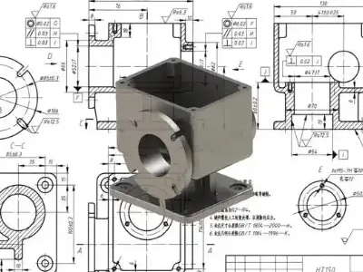
PDF drawings: Fixed-format documents that show dimensions, tolerances, GD&T symbols, notes, and revisions. Native drawing files: CAD-native formats for internal design work, sometimes converted to PDF for the shop floor.
These documents are used for:
- Final inspection and measurement.
- Clarifying design intent and critical features.
- Communicating revision level and engineering change history.
Setup Sheets and Operation Instructions
Setup sheets describe how to prepare the machine for a specific job. They can be simple text documents or structured forms. They typically include:
Program number(s) and file names. Tool list with tool numbers, descriptions, and preset lengths. Fixture description and clamping details. Work coordinate system definitions and how to set them. Notes on coolant, part orientation, and special handling.
Operation instructions may provide step-by-step guidance for machinists, including inspection steps, cleaning between operations, and packaging instructions.
Tool Lists and Preset Data
For efficient setup, many shops maintain:
Tool list files: Identifying all tools needed for a job, including their magazine positions or turret stations. Presetter data exports: Files that contain measured tool lengths and diameters, which can be imported directly into the controller in some systems.
These files reduce manual data entry and help avoid tool length mistakes that can cause crashes or scrap parts.
Industry-Specific CNC File Requirements
Different industries use CNC machines in different ways, which influences the files required and the level of detail needed.
Metal Machining and Mold Making
High-precision metalworking, toolmaking, and mold manufacturing typically require:
Detailed 3D solid models for complex surfaces and tight tolerances. Multiple CAM project files for roughing, semi-finishing, and finishing operations. High-resolution toolpaths and carefully tuned post processors to respect machine dynamics.
Drawings often include GD&T data, tight surface finish specifications, and clear datum structures. Documentation around tool life, cutter compensation, and inspection routines is often formalized.
Sheet Metal Cutting and Fabrication
Laser, plasma, waterjet, and punch presses rely heavily on 2D data. Common file needs include:
2D DXF or DWG profiles for each part or nested sheet. Nesting program files that arrange multiple parts on a sheet. NC program files with kerf compensation, lead-ins, and lead-outs.
Supporting documents may include bend deduction charts, flat pattern drawings, and part labels or marking programs.
Woodworking and Cabinetry
Wood CNC routers and nested-based manufacturing systems often use specialized file types and workflows, but still follow the same basic structure:
CAD drawings or parametric cabinet designs. CAM or nested project files that calculate toolpaths for panel cutting, drilling, and routing. NC program files for each nested sheet or operation.
Information about grain direction, edge banding, and drilling patterns may be stored in additional configuration files or as properties within the design files.
Data Transfer and Storage for CNC Files
Once the required files are created, they must be transferred safely to the CNC machines and managed over time.
DNC Systems and Networked Transfer
Many shops use DNC (Direct Numerical Control) or similar systems to manage NC program files. These systems typically handle:
Central storage of program files with version control. Network transfer to individual machines via Ethernet, serial connections, or other protocols. Access control to ensure only approved programs are loaded on machines.
This reduces the risk of running outdated or incorrect programs and simplifies backups.
File Naming and Revision Control
Consistent naming and revision management are critical. A typical strategy is to encode part number, revision, and operation in the file name. For example, a file name might include customer code, part number, revision level, and machine ID.
Revision control can be handled via:
PLM or PDM systems that manage engineering data. Simple directory structures and naming conventions in smaller operations. Document control procedures linking drawings, models, and NC files to the same revision.
Without clear revision alignment, shops risk machining obsolete designs, leading to rework or scrap.
Typical Pain Points Related to CNC Files
Managing CNC files involves several recurring difficulties. Understanding them helps in designing robust workflows.
Incompatible or Corrupted CAD Files
When customers or internal design teams provide CAD files in formats not directly supported by the CAM system, extra conversion steps are needed. During conversion, geometry can be lost, surfaces can develop gaps, or entities may become non-manifold. This increases programming time and may lead to toolpaths that fail or produce inaccurate parts.
Missing or Ambiguous Manufacturing Information
Even when geometry imports cleanly, the absence of clear tolerances, material specifications, or surface finish requirements forces machinists to make assumptions. This can cause misalignment with design intent, resulting in parts that technically fit the geometry but fail inspection or functional testing.
Desynchronization Between Design, CAM, and NC Files
When a design is updated but associated CAM projects and NC programs are not regenerated, there can be a mismatch between the documentation and actual machining. If revision status is not clearly indicated in file names and documentation, older NC programs may inadvertently be used on newer parts.
Minimum File Set for a Basic CNC Job
The exact file set needed depends on the complexity of the job and the capabilities of the shop. However, a minimal robust set for most CNC projects includes:
| File Type | Purpose | Example Format | Owner/Creator |
|---|---|---|---|
| 3D CAD model or 2D drawing | Defines part geometry | .step, .iges, .dxf | Designer or customer |
| 2D drawing with tolerances | Defines critical dimensions and requirements | .pdf, native CAD | Designer |
| CAM project file | Contains toolpaths, tools, and strategies | CAM-native format | CAM programmer |
| G-code/NC file | Direct input for CNC controller | .nc, .tap, .gcode | CAM system via post processor |
| Setup sheet | Guides machine setup and operation | .pdf, .docx, text | CAM programmer or process engineer |
Additional files, such as tool libraries, macro programs, and inspection plans, can be added as needed to support repeatability and quality control.
How to Decide Which CNC Files You Need
Selecting the appropriate files for CNC machining depends on your role and your place in the supply chain.
If You Are Providing Designs to a CNC Shop
When sending work to a CNC machining service provider, you typically need to supply:
Clean 3D model (for complex parts) or accurate 2D DXF for simple profiles. A 2D drawing or document specifying tolerances, material, surface finish, and any heat treatment or coating requirements. Any special notes on critical features, assembly interfaces, or functional surfaces.
In many cases, you do not need to send CAM files or G-code; the machining center will generate those based on your design files and internal standards.
If You Are Programming and Running Your Own CNC Machines
In an in-house environment, you control the entire chain. In that case you need:
CAD files from design or engineering. CAM project files for each part revision. Post processor configuration tailored to your machines and controllers. NC program files for each operation on each machine. Setup sheets, tool lists, and inspection documents tied to each job.
This internal ecosystem ensures that when a job repeats, you can retrieve the complete set of files and reproduce the part consistently.
Summary
Effective CNC machining depends on a structured set of files that move from design to machine. CAD files describe the part, CAM project files define how it will be machined, G-code or NC files instruct the CNC controller, and supporting documents guide human operators and inspection personnel.
By clearly defining which files are needed at each stage, aligning formats with shop capabilities, and maintaining consistent revision control, you can avoid common pitfalls and maintain reliable CNC production.
