
Turbines are rotary machines that convert the energy of a moving fluid into mechanical power, which is often transformed into electricity through generators. This article explains the main types of turbines, their classification methods, working principles, components, performance characteristics and industrial applications.
Fundamental Concepts of Turbines
A turbine consists of a rotor with blades or buckets that interact with a working fluid such as steam, gas, water or air. The fluid’s kinetic and/or pressure energy is converted into shaft power. The shaft may drive an electric generator, a compressor, a pump, a ship propeller or other machinery.
Basic Energy Conversion Principle
The operation of any turbine is based on the conservation of energy and momentum. A simplified energy balance is:
Input fluid energy = Output shaft power + Fluid exit energy + Losses
Key mechanisms include:
- Acceleration or deceleration of the fluid through nozzles and passages
- Change in direction of fluid flow across the rotor blades
- Pressure drop across fixed and moving blade rows
Impulse vs Reaction Concept
Most turbine configurations can be interpreted in terms of impulse and reaction effects:
- Impulse effect: energy is extracted mainly from the fluid’s velocity (kinetic energy) as it strikes the rotor blades after passing through a nozzle.
- Reaction effect: energy is extracted from the combined pressure and velocity changes occurring both in stationary and moving blades.
The proportion of energy converted by pressure changes in the rotor is characterized by the degree of reaction, which influences blade design, stage loading and overall configuration.
Classification of Turbines
Turbines can be classified using several criteria, each emphasizing different design and operating aspects.
Classification by Working Fluid
One of the most common classification methods is based on the working fluid:
- Steam turbines
- Gas turbines
- Hydraulic (water) turbines
- Wind turbines (air as working fluid)
- Special-purpose turbines (e.g., refrigerant or organic fluid turbines in ORC systems)
Classification by Energy Conversion Mode
According to the energy conversion mode inside the rotor:
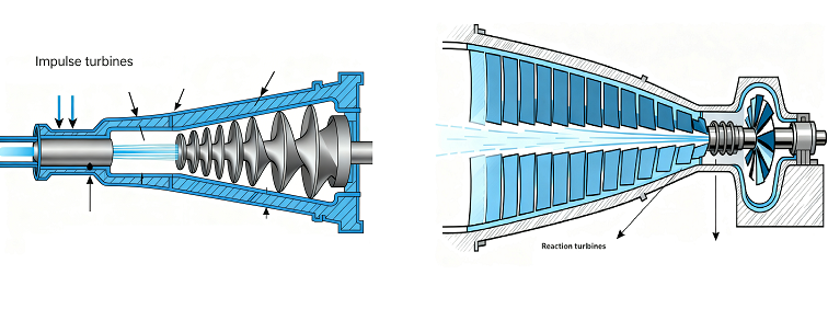
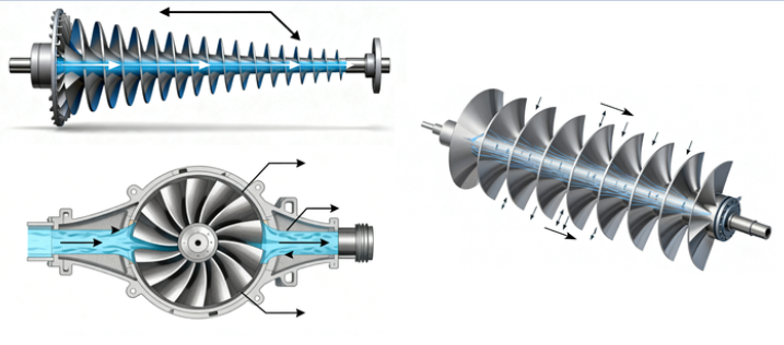
Impulse turbines
In impulse turbines the fluid pressure remains essentially constant across the rotor, and almost all pressure drop occurs in stationary nozzles, producing a high-velocity jet that impinges on the rotor buckets or blades.
Reaction turbines
In reaction turbines the pressure drop is shared between the stationary and moving blades. The rotor passages act as nozzles, causing additional acceleration of the fluid and pressure reduction within the moving blade channels.
Classification by Flow Direction
According to the direction of the fluid flow relative to the axis of rotation:
- Axial-flow turbines: fluid flows parallel to the shaft (common in steam, gas and large wind turbines).
- Radial-flow turbines: fluid flows in a radial direction, either inward or outward (common in some hydraulic and turbocharger turbines).
- Mixed-flow turbines: fluid flow has both axial and radial components (common in certain hydraulic turbines and compact gas turbines).
Classification by Pressure Head or Pressure Ratio
For hydraulic and gas/steam turbines, pressure head or pressure ratio is a key parameter:
Hydraulic turbines are often categorized as:
- High-head turbines (large elevation difference, lower flow rate).
- Medium-head turbines.
- Low-head turbines (small elevation difference, high flow rate).
For gas and steam turbines, the overall pressure ratio across the turbine stages strongly influences the design and choice of the number of stages.
Steam Turbines
Steam turbines convert the thermal energy of high-pressure, high-temperature steam into mechanical work. They are widely used in fossil-fuel, nuclear, biomass, geothermal and industrial cogeneration plants.
Working Principle of Steam Turbines
Steam generated in a boiler or steam generator is expanded through stationary nozzles and moving blade rows. The expansion follows thermodynamic processes between high-pressure inlet and low-pressure exhaust (often to a condenser). The process commonly approximates the Rankine cycle. Staging is used to efficiently handle large pressure drops and to limit blade loading.
Impulse and Reaction Steam Turbines
Most practical steam turbines combine impulse and reaction stages, but many are described according to the predominant principle:
Impulse steam turbines typically use:
- Fixed nozzles or nozzle blocks where most of the pressure drop occurs.
- Rotor wheels equipped with curved buckets; steam jets transfer momentum to the rotor.
Reaction steam turbines usually include:
- Alternating rows of fixed and moving airfoil-shaped blades.
- Pressure drop distributed across both stationary and moving rows, generating lift-like forces on blades.
Condensing vs Back-Pressure Steam Turbines
Steam turbines can also be classified according to exhaust conditions:
- Condensing turbines: exhaust steam enters a condenser at very low pressure (vacuum conditions), maximizing power output.
- Back-pressure (non-condensing) turbines: exhaust steam is delivered at higher pressure for process heating applications in industrial plants or district heating networks.
Typical Operating Parameters for Steam Turbines
| Parameter | Small/Industrial Units | Utility-Scale Units |
|---|---|---|
| Inlet pressure | 1–40 bar | 60–250 bar |
| Inlet temperature | 250–450 °C | 450–620 °C |
| Power output | 0.5–50 MW | 100–1500 MW |
| Rotational speed | 1500–15000 rpm | 3000 or 3600 rpm (grid-synchronous) |
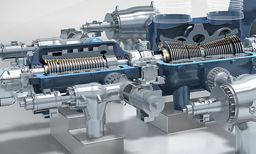
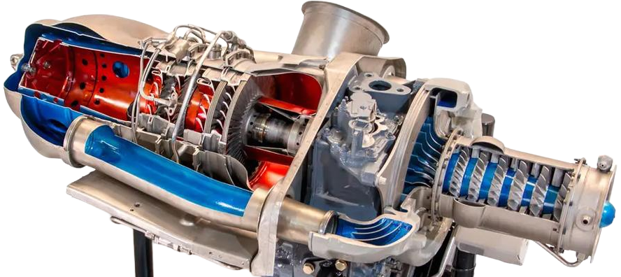
Key Components of Steam Turbines
Steam turbine assemblies generally include:
- Casing with high-, intermediate- and low-pressure sections.
- Rotor with multiple wheels or integral blade rows.
- Stationary blade rows (nozzles) fixed to the casing.
- Shaft seals and bearings.
- Governing system for flow regulation (control valves and nozzles).
- Lubrication and control oil systems.
Typical Considerations for Steam Turbine Selection
Important considerations for selecting a steam turbine type include:
- Available steam pressure and temperature from the boiler or process.
- Required power output and speed.
- Need for extraction or admission ports for process steam.
- Condensing or back-pressure configuration depending on heat recovery requirements.
Gas Turbines
Gas turbines are internal combustion engines that operate on the Brayton cycle. They draw in ambient air, compress it, mix it with fuel, burn the mixture and expand the high-temperature gas through turbine stages that drive both the compressor and an external load.
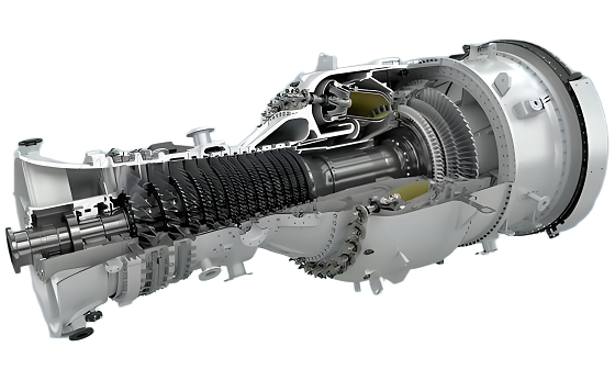
Open-Cycle Gas Turbines
In open-cycle gas turbines the working fluid (air and combustion products) passes through the engine once and is then exhausted to the atmosphere. These units are widely used for power generation, mechanical drive (e.g., compressors, pumps) and aviation propulsion.
Characteristic features include:
- Axial or centrifugal compressor stages.
- Combustion chambers (can-annular or annular).
- Single or multiple turbine stages for compressor drive and power output.
- Exhaust diffuser and stack or propulsion nozzle.
Closed-Cycle and Indirectly Fired Gas Turbines
Closed-cycle gas turbines recirculate a working fluid such as helium, nitrogen or air in a closed loop through external heat exchangers. They are used in specific industrial or experimental applications where particular working fluid properties are needed.
Indirectly fired configurations use a heat exchanger to transfer heat from an external combustion process to the working fluid, allowing separation between combustion gases and turbine working fluid.
Industrial vs Aero-Derivative Gas Turbines
Gas turbines can be divided into heavy-duty industrial designs and aero-derivative units derived from aircraft engines:
- Industrial gas turbines: robust, often heavier, optimized for long service intervals and stationary operation.
- Aero-derivative gas turbines: lighter, higher power-to-weight ratio, faster start-up, often used for peaking power, offshore platforms and mobile units.
Key Performance Parameters for Gas Turbines
Important operating parameters include:
- Compressor pressure ratio (commonly around 8–30 for many industrial units).
- Turbine inlet temperature (often in the range of 1000–1500 °C depending on design and materials).
- Power output (from a few MW for small units to hundreds of MW for large heavy-duty machines).
- Rotational speeds (often 3000 or 3600 rpm for directly coupled generators; much higher for aero-derivative cores).
Combined Cycle Power Plants
In many power plants, gas turbines are combined with steam turbines. The hot exhaust from the gas turbine is routed through a heat recovery steam generator, producing steam that drives a steam turbine. This combined cycle arrangement improves overall energy utilization and allows the use of multiple turbine types in one plant.
Hydraulic (Water) Turbines
Hydraulic turbines convert the potential and kinetic energy of water into mechanical power. They are central components of hydropower plants and pumped-storage facilities.
Classification of Hydraulic Turbines
Hydraulic turbines are typically categorized by the method of energy conversion and the head range.
Impulse hydraulic turbines:
- Extract energy almost exclusively from water jet velocity.
- Operate at atmospheric pressure around the runner.
- Use nozzles to convert head into high-speed jets that strike the runner buckets.
Reaction hydraulic turbines:
- Operate fully submerged under pressure.
- Convert energy through pressure and velocity changes within the runner passages.
- Require a casing and often a draft tube for pressure recovery.
Main Types of Hydraulic Turbines
| Turbine Type | Type (Impulse/Reaction) | Typical Head Range | Typical Flow Range | Common Applications |
|---|---|---|---|---|
| Pelton | Impulse | 150–1800 m | Low to medium | High-head mountainous hydropower plants |
| Turgo | Impulse | 50–400 m | Low to medium | Medium-head hydropower, compact schemes |
| Cross-flow (Banki) | Impulse-like | 5–200 m | Low to medium | Small and micro hydropower |
| Francis | Reaction (mixed flow) | 20–700 m | Medium | Large and medium-head hydropower plants |
| Kaplan | Reaction (axial flow) | 2–70 m | High | Low-head run-of-river and dam plants |
| Propeller | Reaction (axial flow) | 2–50 m | High | Low-head with relatively constant operating conditions |
Pelton Turbines
Pelton turbines are impulse machines used for high-head, relatively low-flow conditions. Key characteristics:
- One or more nozzles directing high-velocity water jets onto double-cup buckets mounted on the periphery of a wheel.
- Speed regulation by needle valves and jet deflectors.
- Runner usually operating at atmospheric pressure, simplifying casing design.
Francis Turbines
Francis turbines are widely used reaction turbines suitable for medium heads. They feature:
- Spiral casing delivering water circumferentially to stay vanes and guide vanes.
- Guide vanes for flow regulation and direction control.
- Runner with curved blades where flow transitions from radial to axial (mixed flow).
- Draft tube for pressure recovery and discharge to the tailrace.
Kaplan and Propeller Turbines
Kaplan turbines are axial-flow reaction turbines with adjustable runner blades and often adjustable guide vanes, allowing high efficiency over a range of flows. Propeller turbines are similar but usually have fixed runner blades, suitable for more constant operating conditions.
Hydraulic Turbine Considerations
Selection and design of hydraulic turbines require attention to:
- Available head and flow rate throughout the year.
- Cavitation risk, evaluated using parameters such as net positive suction head and cavitation coefficients.
- Speed regulation and grid connection requirements.
- Sediment, debris and water quality influencing wear and maintenance.
Wind Turbines
Wind turbines extract kinetic energy from moving air and convert it into mechanical and electrical power. Modern wind turbines are predominantly horizontal-axis machines with large rotor diameters.
Horizontal-Axis vs Vertical-Axis Wind Turbines
Wind turbines can be categorized by rotor axis orientation:
- Horizontal-axis wind turbines (HAWTs): rotor axis is horizontal and usually aligned with the wind direction. They dominate utility-scale wind power installations.
- Vertical-axis wind turbines (VAWTs): rotor axis is vertical; examples include Darrieus and Savonius types. They are used in specific niche applications and small-scale systems.
Lift-Based vs Drag-Based Designs
Most modern wind turbines are lift-based machines using aerodynamic airfoils to produce torque efficiently. Drag-based devices such as simple cup anemometer-type rotors provide lower efficiency and are used mainly for small applications.
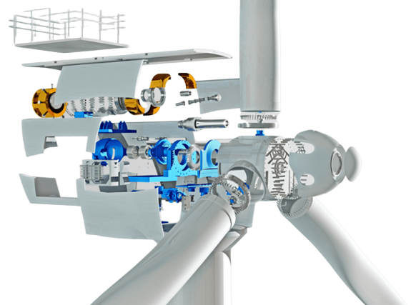
Key Components of Modern Wind Turbines
Typical large horizontal-axis wind turbines include:
- Rotor with two or three blades attached to a hub.
- Nacelle containing gearbox (if present), generator, yaw system and control equipment.
- Tower providing elevation to access stronger winds.
- Pitch system to adjust blade angle for power regulation and load control.
- Yaw system to orient the rotor toward the wind.
Operating Characteristics
Important operating parameters are:
- Rated power output (from a few kilowatts for small units to multiple megawatts for utility-scale machines).
- Cut-in, rated and cut-out wind speeds, typically in the range 3–4 m/s (cut-in) to around 20–25 m/s (cut-out).
- Rotor speed, often variable and controlled via power electronics and pitch systems.
Typical Considerations for Wind Turbines
Key considerations include:
- Wind resource characteristics at the site (wind speed distribution, turbulence).
- Grid connection requirements and power quality.
- Structural loads on blades, tower and foundations.
- Noise, visual impact and land use constraints.
Special-Purpose and Other Turbine Types
Beyond the primary categories, specialized turbines are used in particular industrial and energy systems.
Micro Turbines
Micro gas turbines are small power units, typically in the range of tens to hundreds of kilowatts. They often use:
- High-speed single-shaft or two-shaft configurations.
- Recuperators to recover exhaust heat for preheating compressed air.
- Gaseous or liquid fuels for distributed generation and combined heat and power (CHP).
Organic Rankine Cycle (ORC) Turbines
ORC systems use organic working fluids with lower boiling points than water. Turbines operating with these fluids can be:
- Radial inflow or axial-flow types.
- Designed for low to medium temperatures (often 80–300 °C) such as waste heat recovery or geothermal applications.
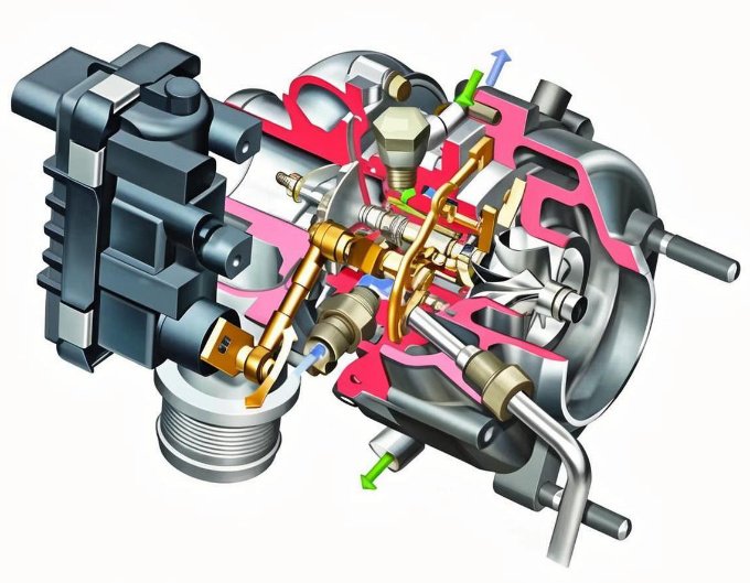
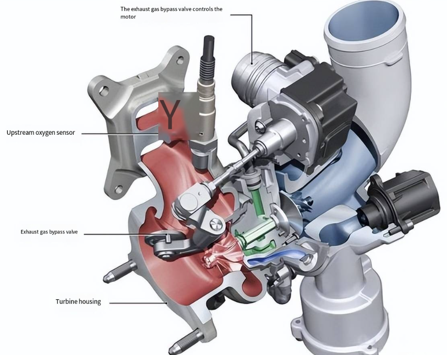
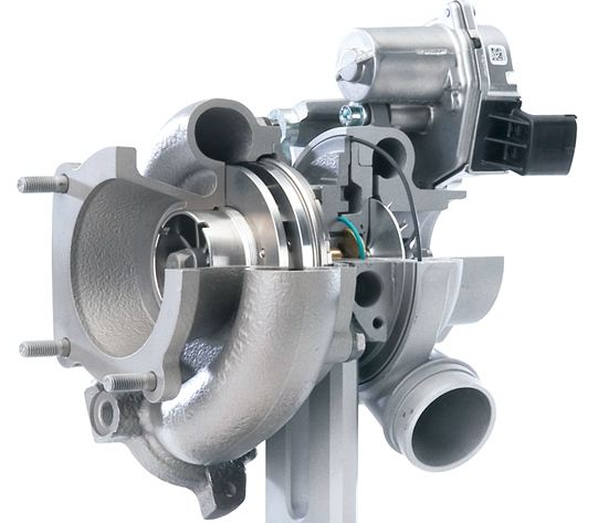
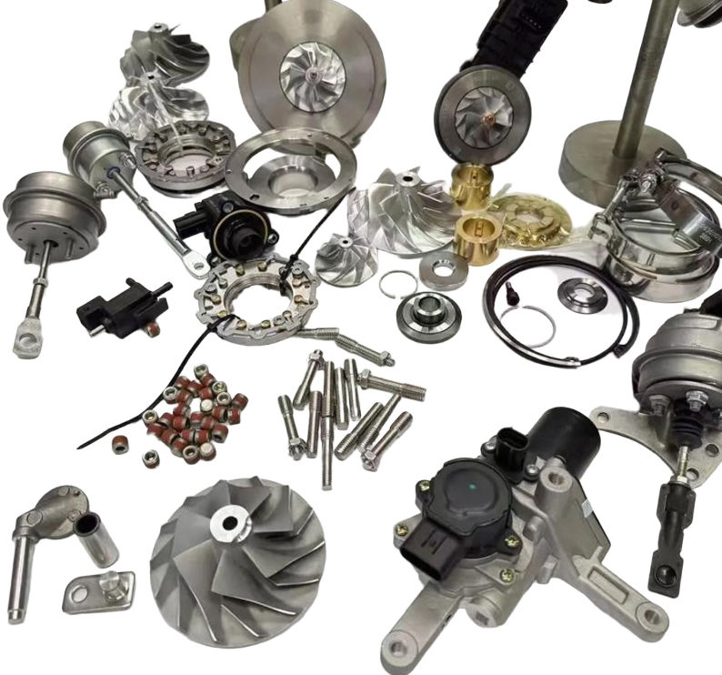
Turbines in Turbochargers and Process Machinery
In automotive and industrial turbochargers, radial inflow turbines drive compressors using exhaust gases. Process industries employ expanders or turbine expanders to recover work from process pressure drops, such as in gas processing plants.
Marine and Aerospace Turbines
Marine gas turbines drive ship propellers or waterjets through reduction gearboxes. In aerospace applications, turbines are integral parts of turbojet, turbofan, turboprop and turboshaft engines, where they drive compressors and in some cases propellers or helicopter rotors.
Key Design Parameters and Performance Metrics
Although each turbine type has specific design features, several common parameters are used to characterize and compare turbine designs.
Specific Speed
Specific speed is a dimensionless or scaled parameter used to relate turbine speed, power and head (or pressure). It helps classify turbines and guides preliminary selection and scaling. High specific speed usually corresponds to axial-flow turbines, while low specific speed corresponds to radial or impulse machines.
Stage Loading and Flow Coefficients
For steam and gas turbines, dimensionless coefficients characterize blade aerodynamics and stage performance:
- Flow coefficient (ratio of meridional velocity to blade speed).
- Loading coefficient (ratio of specific work to blade speed squared).
These parameters influence blade shape, number of stages and overall spool layout.
Efficiency Definitions
Common efficiency measures include:
- Isentropic efficiency: ratio of actual work to ideal isentropic work for the same inlet and outlet states.
- Mechanical efficiency: ratio of shaft power delivered to the load to power developed by the turbine rotor, accounting for bearing and seal losses.
- Overall efficiency: product of aerodynamic, mechanical and generator efficiencies where applicable.
Materials and Cooling Considerations
For high-temperature turbines (gas and some steam stages), materials and cooling strongly affect allowable operating conditions. Blades and vanes may incorporate internal cooling passages, film cooling holes and thermal barrier coatings. Turbine casings and rotors are sized to limit stresses under thermal and centrifugal loading.
Applications and System Integration
Turbines are integrated into numerous energy and industrial systems. Understanding their roles within these systems is important for proper selection and operation.
Electric Power Generation
Major power generation applications include:
- Steam turbines in coal, nuclear, biomass and solar thermal plants.
- Gas turbines and combined cycle plants using natural gas or other fuels.
- Hydraulic turbines in run-of-river, reservoir and pumped-storage hydropower plants.
- Wind turbines in onshore and offshore wind farms.
Mechanical Drive and Industrial Processes
Turbines often drive:
- Compressors in gas pipelines and petrochemical processes.
- Pumps in large-scale pumping stations and power plants.
- Ship propulsion systems, especially where compact, high-power rotary machines are needed.
Heat and Power Cogeneration
In combined heat and power systems, steam and gas turbines can deliver both electricity and useful heat. Back-pressure steam turbines provide process steam, and gas turbines may supply exhaust heat for industrial drying, district heating or additional steam generation.
FAQ about Types of Turbines
What is the main difference between impulse and reaction turbines?
In impulse turbines, almost all the pressure drop takes place in stationary nozzles, creating high-velocity jets that strike the rotor buckets at nearly constant pressure across the rotor. In reaction turbines, the pressure drop is distributed between stationary and moving blades, so the rotor passages act like nozzles and the fluid experiences both velocity and pressure changes while passing through the rotor.
How do steam, gas, water and wind turbines differ in their working fluids and cycles?
Steam turbines use water steam and generally operate in a Rankine cycle, with steam produced in a boiler and condensed after expansion. Gas turbines use air and combustion products in a Brayton cycle, with compression, combustion and expansion in one continuous flow. Hydraulic turbines use water under pressure head in open-channel or pressurized systems, converting potential and kinetic energy directly to shaft power. Wind turbines use atmospheric air flow and extract kinetic energy without a closed thermodynamic cycle, relying on aerodynamic lift on rotor blades.
Which turbine type is most suitable for high-head hydropower sites?
For high-head hydropower sites, impulse turbines such as Pelton machines are typically preferred. They are designed to handle large elevation differences with relatively low flow rates by converting the head into high-velocity water jets that act on buckets mounted on the runner. Their configuration allows efficient operation under high-head conditions while limiting structural loads on the runner and casing.
Why are combined cycle plants using both gas and steam turbines?
Combined cycle plants use gas turbines to generate power and then route the high-temperature exhaust gases to a heat recovery steam generator, which produces steam to drive a steam turbine. This configuration allows better use of the fuel’s energy content by recovering heat that would otherwise be wasted, increasing the total power output from the same fuel input and making more effective use of both turbine types.
