
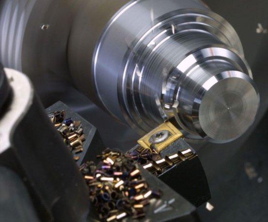
CNC turning machines, often called CNC lathes or turning centers, are computer-controlled machine tools designed to produce rotationally symmetrical parts with high precision and repeatability. They remove material from rotating workpieces using stationary or guided cutting tools, following programmed toolpaths. Understanding how CNC turning machines work requires examining the machine structure, control system, motion axes, tooling, workholding, cutting parameters, and programming workflow.
Basic Principle of CNC Turning
CNC turning is a subtractive manufacturing process in which a workpiece rotates while a cutting tool moves along one or more linear axes to remove material. The main characteristics are:
- The workpiece is clamped and rotated by the spindle.
- Cutting tools are mounted on a tool post, turret, or tool magazine.
- Tool motion is controlled along linear axes (typically X and Z) and sometimes Y or additional axes.
- A CNC controller executes a part program (usually G-code) to coordinate spindle speed, feed rate, and tool movements.
The result is a highly controlled machining process that can produce shafts, bushings, pins, flanges, and complex rotational geometry with tight dimensional tolerances and good surface finishes.
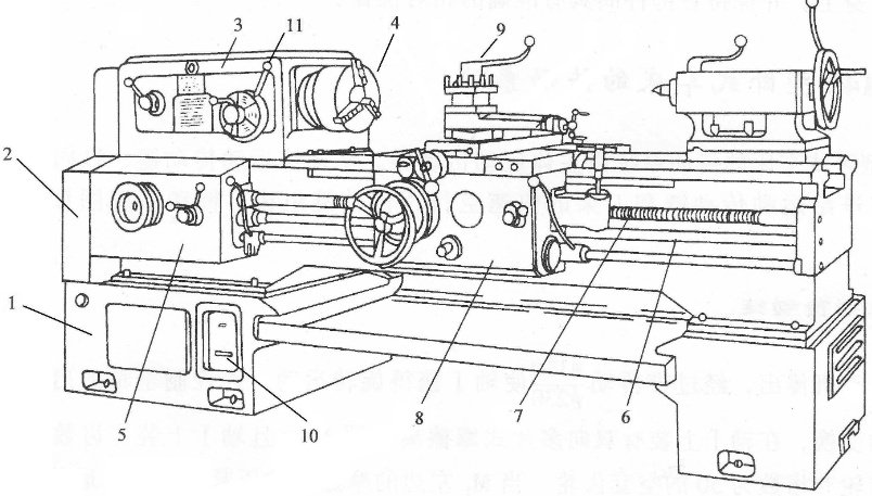
Major Components of a CNC Turning Machine
A CNC turning machine is an integrated system composed of mechanical, electrical, and electronic elements. The main components include:
Machine Bed and Base
The bed or base is the rigid foundation of the machine. It supports the headstock, tailstock, carriage, and other assemblies. Key aspects:
- Typically made from cast iron or a heavily ribbed welded structure for high stiffness.
- Designed to damp vibrations generated during cutting.
- Incorporates linear guideways or box ways for axis motion.
Headstock and Spindle
The headstock houses the spindle, which rotates the workpiece. It is one of the most critical assemblies for accuracy and productivity.
Typical characteristics of a CNC lathe spindle:
- Drive type: belt-driven, gear-driven, or built-in motor spindle.
- Speed range: from very low rpm for large diameters to high rpm for small, precision parts (e.g., 20–5,000 rpm or higher depending on machine class).
- Bearings: high-precision angular contact bearings for radial and axial load capacity.
- Through-hole: allows bar material to pass through for bar-fed production.
Many machines also include spindle orientation capability so the spindle can stop at a precise angular position, enabling features like keyway machining, drilling on the periphery, and synchronized operations with driven tools.
Chuck and Workholding Devices
The spindle nose carries a chuck or other workholding device to grip the workpiece. Common types:
- 3-jaw self-centering chucks for general round workpieces.
- 4-jaw independent chucks for non-round or off-center turning.
- Collet chucks for high-precision bar work and small diameters.
- Special fixtures and mandrels for unique geometries.
Hydraulic or pneumatic actuation is widely used for fast and repeatable clamping. Workholding quality directly affects part concentricity, runout, and process reliability.
Tailstock and Sub-Spindle
On many CNC lathes, a tailstock supports long workpieces to prevent deflection under cutting forces. It typically includes:
- A quill with a live center or drill chuck.
- Manual or programmable positioning along the bed.
On turning centers with a sub-spindle, the auxiliary spindle can:
- Grip the part from the main spindle for back-side machining.
- Perform simultaneous operations on both ends of the workpiece.
- Enable complete machining in a single setup, reducing handling.
Carriage, Cross-Slide, and Turret
The carriage and cross-slide provide the main linear motions of the cutting tools. Key elements:
- Z-axis: parallel to the spindle axis, typically the direction of longitudinal turning.
- X-axis: radial direction, controlling the cutting depth and diameter.
- Turret: an indexable tool-holding device capable of quickly changing tools.
Turrets can be:
- Horizontal or vertical configuration.
- Servo-indexed for fast, precise positioning.
- Equipped with driven (live) tool stations for milling, drilling, and tapping with the workpiece held in the spindle.
Feed Drives, Ballscrews, and Guideways
Precision movements along the axes are achieved through feed drive systems:
- Servo motors deliver controlled rotational motion.
- Ballscrews convert rotational motion to linear motion with minimal backlash.
- Linear guideways or hardened box ways support and guide the moving assemblies.
High-quality feed components are essential for accurate positioning, smooth surface finish, and consistent toolpath execution.
CNC Control Unit
The CNC control is the brain of the machine. It interprets part programs and coordinates all machine functions. Main functions include:
- G-code interpretation (movement commands, tool changes, spindle control).
- Axis interpolation and trajectory planning for smooth tool motion.
- Management of offsets, tool data, and work coordinate systems.
- Real-time monitoring of spindle load, alarms, and safety interlocks.
Modern controls also provide conversational programming modes, toolpath visualization, diagnostic tools, and networking interfaces for data exchange.
Hydraulic, Pneumatic, and Coolant Systems
Auxiliary systems support machining operations:
- Hydraulics for chuck clamping, turret indexing, and tailstock actuation.
- Pneumatics for part blow-off, part ejectors, and some clamping functions.
- Coolant systems for heat removal, chip evacuation, and lubrication at the cutting zone.
Coolant delivery parameters such as pressure, flow rate, and nozzle positioning significantly influence tool life and chip control.
Coordinate System and Motion Axes in CNC Turning
Understanding the coordinate system is fundamental to how CNC turning machines work. The CNC controller uses standardized axis definitions to position tools relative to the workpiece.
Axis Definitions
A typical 2-axis CNC lathe uses:
- Z-axis: parallel to the spindle centerline, positive direction often away from the chuck.
- X-axis: radial direction, usually positive towards the operator on slant-bed lathes. The X-axis value often represents the diameter (diameter programming) rather than the radius.
Additional axes on more complex machines can include:
- C-axis: spindle rotation under servo control, used for indexed or interpolated milling.
- Y-axis: perpendicular to both X and Z, enabling off-center milling, drilling, and complex contouring.
- B-axis: swiveling toolhead or spindle axis on some advanced turning centers.
Work Coordinate Systems
The work coordinate system (such as G54, G55, etc.) defines the origin (zero point) relative to the part. Typical practice:
- Z zero at the finished face or a reference face of the workpiece.
- X zero at the spindle centerline (axis of rotation).
Accurate setting of work coordinates ensures that toolpaths align correctly with the physical part.
Turning Operations and Machining Cycles
CNC turning machines perform a variety of operations using standardized cycles and tool motions. These operations are combined in a program to produce the final part.
Facing
Facing involves moving a tool in the X direction to generate a flat surface perpendicular to the spindle axis. Typical sequence:
- Approach the workpiece with the tool near the outer diameter.
- Feed the tool towards the center, removing material across the face.
- Control feed rate and depth to achieve the desired surface finish and flatness.
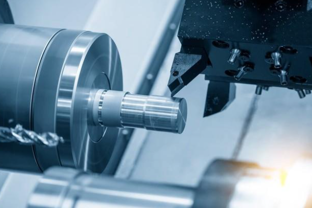
Straight Turning and Shouldering
Straight turning (or longitudinal turning) reduces the diameter along a defined length:
- The tool moves parallel to the Z-axis while the workpiece rotates.
- Multiple passes may be required, starting with roughing passes at higher depths of cut and ending with finishing passes at lower depths of cut.
Shouldering creates steps or shoulders where diameter changes occur, requiring precise control of tool entry and exit to avoid marks and maintain square shoulders.
Taper Turning
Taper turning produces conical surfaces by coordinated movement of X and Z axes. A linear relationship between diameter and length defines the taper. The CNC controller handles the interpolation to achieve the defined angle or taper per length.
Grooving and Parting
Grooving uses narrow tools to cut slots or recesses in the radial direction. Parting (cut-off) is a special form of grooving used to separate the finished part from the bar or stock.
Key considerations:
- Proper tool rigidity and overhang control to minimize vibration.
- Adequate coolant to evacuate chips from narrow grooves.
- Lower cutting speeds near the center to avoid excessive heat and tool failure.
Thread Turning
CNC lathes can cut external and internal threads by synchronizing tool feed with spindle rotation:
- The tool follows a helical path defined by the thread pitch.
- Thread cycles (e.g., G76, G92) automate multiple passes, depth increments, and infeed strategies.
- Accurate spindle speed control is necessary for consistent thread profiles.
Boring and Internal Machining
Internal diameters are machined using boring bars or internal grooving tools:
- The tool enters the pre-drilled hole and enlarges it to the required diameter.
- Internal threads, grooves, and tapers can also be machined.
- Tool deflection is a critical factor due to long tool overhang; this affects surface finish and accuracy.
Canned and Custom Cycles
Many CNC controls offer canned cycles that simplify programming of common turning operations. Examples include cycles for:
- Rough turning and facing with automatic depth-of-cut distribution.
- Finishing complex profiles defined by a series of coordinates.
- Threading cycles with control over infeed angle and number of passes.
These cycles reduce programming time and ensure consistent machining strategies across similar parts.
Tooling for CNC Turning
Tooling is central to how CNC turning machines work, as it directly affects cutting performance, surface quality, and tool life.
Tool Holders and Inserts
Most CNC turning tools use indexable inserts clamped in rigid tool holders. Key aspects:
- Insert shapes: CNMG, DNMG, VNMG, etc., offering various corner radii and approach angles.
- Insert grades: carbide, cermet, ceramic, CBN, or PCD, selected based on workpiece material and cutting conditions.
- Tool holder geometry: affects approach angle, chip flow, and accessibility.
Indexable inserts allow quick replacement without resetting tool geometry, helping to maintain productivity and consistency.
Tool Stations and Turret Layout
The turret may have multiple tool stations, each capable of holding:
- External turning tools.
- Boring bars and internal tools.
- Grooving and parting tools.
- Drills, taps, and driven tool holders on machines with live tooling.
Turret configuration and station capacity influence setup flexibility, determining how many operations can be completed in a single setup.
Tool Geometry and Cutting Edge Preparation
Tool geometry strongly affects cutting forces, chip formation, and surface finish:
- Rake angle: influences cutting forces and chip flow.
- Relief (clearance) angle: prevents rubbing and excessive heat.
- Corner radius: affects surface finish and tool strength.
Cutting edge preparation (hone, chamfer) tailors the edge to specific materials and cutting conditions to balance sharpness and durability.
Cutting Parameters and Their Influence
Cutting parameters define how aggressively material is removed and have a direct impact on productivity, tool life, and part quality. The three fundamental parameters are cutting speed, feed, and depth of cut.
Cutting Speed (Vc)
Cutting speed is the speed at which the cutting edge engages the workpiece surface, usually expressed in meters per minute (m/min) or surface feet per minute (sfm). The relationship between spindle speed (rpm), workpiece diameter (D), and cutting speed (Vc) is:
Vc = π × D × rpm
Controls commonly offer constant surface speed modes that automatically adjust spindle rpm as the tool moves radially to maintain a near-constant cutting speed.
Feed Rate (f)
Feed rate is the distance the tool advances along the workpiece per revolution (mm/rev or in/rev) or per minute (mm/min or in/min). For turning, feed per revolution is commonly used. Increasing feed rate:
- Raises material removal rate.
- Increases cutting forces and tool load.
- Typically reduces surface finish quality if excessive.
Depth of Cut (ap)
Depth of cut is the thickness of material removed in a single pass measured radially. Larger depths of cut increase productivity but generate higher forces and may lead to deflection, chatter, or thermal issues if not supported by the machine rigidity and tool capability.
Interrelation of Cutting Parameters
Cutting speed, feed, and depth of cut must be balanced based on:
- Workpiece material properties (hardness, toughness, thermal conductivity).
- Tool material and geometry.
- Machine power and rigidity.
- Required surface finish and dimensional accuracy.
| Operation Type | Material Example | Cutting Speed (m/min) | Feed (mm/rev) | Depth of Cut (mm) |
|---|---|---|---|---|
| Rough turning | Medium carbon steel | 150–250 | 0.25–0.45 | 2.0–4.0 |
| Finish turning | Medium carbon steel | 180–280 | 0.10–0.25 | 0.3–1.0 |
| Rough turning | Aluminum alloy | 300–600 | 0.30–0.60 | 2.0–5.0 |
| Finish turning | Aluminum alloy | 400–800 | 0.08–0.20 | 0.2–0.8 |
These ranges are indicative; actual values are chosen according to the specific tool and machine capabilities, as well as the desired quality level.
Programming and G-Code in CNC Turning
CNC turning machines operate based on part programs, typically written in G-code, that describe motions, tool changes, and auxiliary functions. Understanding programming is essential for controlling how the machine works.
Program Structure
A basic CNC turning program includes:
- Header with program number and identification.
- Safety line with modal codes (units, plane selection, compensation modes).
- Tool calls and spindle commands.
- Motion commands (rapid, linear, circular, cycles).
- End-of-program and optional return to initial position.
Common G and M Codes
Typical codes encountered on CNC lathes include:
- G00: rapid positioning.
- G01: linear interpolation at feed rate.
- G02/G03: circular interpolation (clockwise/counterclockwise).
- G96/G97: constant surface speed mode / constant rpm mode.
- G54–G59: work coordinate systems.
- G71–G76: roughing, finishing, and threading cycles (naming may vary by control).
- M03/M04: spindle on clockwise/counterclockwise.
- M05: spindle stop.
- M08/M09: coolant on/off.
- M06 or turret-specific commands: tool change or turret index.
Tool Offsets and Wear Compensation
Tool offsets define the position of each tool tip relative to a reference point. Two key types:
- Geometry offsets: store the initial tool length and radius values.
- Wear offsets: small adjustments applied to compensate for tool wear or minor deviations.
| Offset Type | Purpose | Adjustment Scale |
|---|---|---|
| Geometry offset | Defines nominal tool tip position and radius | May be several millimeters depending on tool length |
| Wear offset | Fine-tunes size and position during production | Typically within ±0.50 mm or less |
Proper use of offsets allows operators to adjust dimensions without altering the base program, supporting stable and repeatable production.
Workflow: From Raw Material to Finished Part
The operational workflow on a CNC turning machine can be described as a sequence of steps, from preparation to final inspection.
1) Setup and Preparation
- Select workholding devices suitable for the part (chuck, collet, fixture).
- Mount the workpiece and ensure secure clamping.
- Install tools in the turret, ensuring correct orientation and clamping torque.
- Set work coordinate zero and tool geometry offsets using a tool presetter or touch-off method.
2) Programming and Verification
- Prepare the G-code program, either manually or using CAM software.
- Load the program into the CNC control.
- Simulate the program on the control or offline to check for collisions, over-travel, and logic errors.
3) Trial Machining
- Run the program in single-block or dry-run mode without cutting, if necessary.
- Perform a first-off machining with reduced feed and speed for safety.
- Measure critical dimensions and inspect surface quality.
- Apply wear offsets or minor program edits if required.
4) Production Machining
- Once the process is validated, run the program at full parameters.
- Monitor tool wear, chip flow, and machine alarms.
- Replace inserts or tools based on predetermined tool life or condition.
5) Inspection and Quality Control
- Measure parts using calipers, micrometers, bore gauges, or CMMs.
- Check dimensions, form, and surface finish according to drawing requirements.
- Document results as part of process control and traceability.
Precision, Accuracy, and Repeatability
CNC turning machines are designed to consistently produce parts within specified tolerances. Three key concepts are:
- Accuracy: how close a produced dimension is to the nominal value.
- Repeatability: the ability to produce the same dimension consistently across multiple parts.
- Resolution: the smallest increment of motion the control can command.
Factors Affecting Accuracy
Multiple factors influence how precisely a CNC turning machine can work:
- Machine structural rigidity and thermal stability.
- Axis positioning accuracy and backlash compensation effectiveness.
- Tool wear and deflection, especially with long overhangs.
- Workpiece clamping and deformation due to clamping forces.
- Cutting forces and vibration during heavy roughing cuts.
Thermal Effects
Heat from the spindle, motors, and cutting zone can cause expansion in machine components and the workpiece, affecting dimensions. To minimize thermal impact:
- Machines use temperature-stable structures and sometimes thermal compensation algorithms.
- Coolant helps control workpiece and tool temperatures.
- Stable environmental conditions (ambient temperature control) help maintain dimensional consistency.
Compensation Mechanisms
Modern CNC controls provide compensation functions such as:
- Backlash compensation for axis drive systems.
- Pitch error compensation for ballscrews.
- Thermal growth compensation models based on sensor input or empirical data.
Materials Commonly Machined on CNC Turning Machines
CNC turning machines handle a wide range of machinable materials. Material selection affects cutting conditions, tool choice, and achievable surface finishes.
Metals
- Carbon and alloy steels: widely used in shafts, fasteners, and structural components.
- Stainless steels: used where corrosion resistance is critical; may require optimized cutting data due to work hardening tendency.
- Aluminum and aluminum alloys: machinable at high speeds with good chip formation and surface finish.
- Copper and brass: good machinability, often used for electrical and fluid handling components.
- Titanium and high-temperature alloys: require careful parameter selection and robust tooling due to high strength and poor thermal conductivity.
Non-Metallic Materials
- Engineering plastics (e.g., POM, nylon, PEEK): require sharp tools and consideration of heat buildup and deformation.
- Composite materials: may require special tools and cutting strategies to avoid delamination or fiber damage.
Chip Formation and Chip Control
Chip formation and evacuation significantly influence machine performance and reliability during CNC turning.
Chip Formation Basics
As the cutting edge engages the material, it shears off chips whose shape depends on:
- Workpiece material.
- Tool geometry and chipbreaker design.
- Cutting speed, feed, and depth of cut.
Controlled chip formation is essential to prevent chip wrapping, tool damage, and surface defects.
Chipbreaker and Tool Design
Many inserts incorporate chipbreakers designed to:
- Curl and break chips into manageable lengths.
- Direct chips away from the cutting zone.
- Reduce cutting forces and improve chip evacuation.
Coolant and Chip Evacuation
Coolant jets help transport chips away from the tool and workpiece. For deep grooves and bores, internal coolant-fed tools or high-pressure coolant systems can be used to ensure reliable chip evacuation and consistent tool performance.
Safety and Operational Considerations
Safe and efficient operation is integral to how CNC turning machines work in practice. Machine design incorporates safety features, and operators must follow established procedures.
Machine Enclosures and Interlocks
- Full enclosures contain chips and coolant and protect the operator from rotating parts.
- Door interlocks prevent spindle rotation and axis motion when doors are open.
- Emergency stop buttons immediately cut power to motion systems if pressed.
Workholding and Tool Clamping Safety
Improper clamping can lead to part ejection or tool failure. Safe practices include:
- Ensuring clamping forces are sufficient for the cutting conditions.
- Regular inspection of chuck jaws and tool holders for wear or damage.
- Using appropriate maximum spindle speed limits for large or unbalanced parts.
Operational Pain Points
Certain recurring issues can hinder CNC turning performance if not managed systematically:
- Chip buildup: leads to tool breakage or part damage if chips are not controlled.
- Excessive tool wear: increases dimensional variation and may cause sudden failures.
- Vibration and chatter: degrade surface finish and can reduce tool life.
- Thermal drift: causes size variations over longer production runs if not compensated.
Addressing these issues typically involves optimizing cutting parameters, improving tooling selection, and ensuring consistent machine maintenance.
Process Optimization and Best Practices
Optimizing CNC turning operations focuses on consistent quality, predictable tool life, and efficient cycle times.
Tool Management
- Define tool life criteria based on wear, surface finish, or dimensional drift.
- Use tool life monitoring functions in the CNC control to trigger automatic tool changes or warnings.
- Group tools logically in the turret to minimize tool change times and interference.
Parameter Optimization
- Adjust cutting speed to balance productivity and tool life for each material and tool grade.
- Optimize feed to achieve required surface finish without excessive tool loading.
- Set depth of cut to maximize metal removal within machine power and rigidity limits.
Setup Reduction
- Use quick-change tool holders to reduce downtime between setups.
- Employ standardized workholding devices where possible.
- Implement consistent work coordinate and offset management to speed up changeovers.
Quality Assurance Practices
- Define critical dimensions and inspection intervals for in-process checks.
- Use statistical process control methods where applicable to monitor stability.
- Maintain calibration of measurement tools used on the shop floor.
FAQ About How CNC Turning Machines Work
What is the main difference between CNC turning and CNC milling?
The main difference lies in which component rotates. In CNC turning, the workpiece rotates while the cutting tool moves linearly, making the process ideal for cylindrical or rotationally symmetrical parts. In CNC milling, the cutting tool rotates and the workpiece is typically stationary or moves linearly/rotationally on machine axes, making it better suited for prismatic shapes, pockets, and complex 3D surfaces. Many modern turning centers include driven tools and additional axes, allowing limited milling operations with the workpiece held in the spindle.
How accurate are CNC turning machines in typical production?
Accuracy depends on machine class, condition, setup quality, and environmental stability. Well-maintained CNC turning machines commonly hold dimensional tolerances in the range of ±0.010 mm to ±0.020 mm for general work, and tighter tolerances are achievable with precision machines, optimized setups, and controlled conditions. Repeatability is often better than absolute accuracy, allowing consistent production once offsets and compensation values are correctly tuned for a given part and process.
