
Hardcoat anodizing, also known as hard anodizing or Type III anodizing, is a controlled electrochemical process that forms a thick, dense aluminum oxide layer on CNC machined aluminum components. It is widely used when wear resistance, corrosion resistance, and dimensional stability are critical. This guide explains the process from a production and engineering perspective, focusing on tolerances, masking, finishing, and key technical parameters.
Fundamentals of Hardcoat Anodizing
Hardcoat anodizing converts the surface of aluminum into a hard, ceramic-like aluminum oxide layer. Unlike coatings that are applied on top of the metal, the anodic layer is grown from the base material, forming an integral part of the surface. This has significant implications for tolerances, fatigue, and subsequent machining or assembly.
Basic process principle
Hardcoat anodizing is an electrolytic oxidation process performed in a cold sulfuric acid-based electrolyte under high current density. The aluminum component acts as the anode. When current flows, aluminum at the surface reacts with oxygen ions to form aluminum oxide. The coating grows both inward into the base metal and outward from the original surface.
Hardcoat vs conventional anodizing
Compared with conventional decorative anodizing (often called Type II), hardcoat anodizing exhibits:
- Greater coating thickness, typically 25–75 μm (0.001–0.003 in) versus about 5–25 μm (0.0002–0.001 in) for Type II.
- Higher hardness, typically 400–600+ HV, improving wear resistance and reducing galling.
- Higher abrasion resistance and improved service life in sliding or repetitive-contact applications.
- Lower porosity and better barrier properties for corrosion protection, especially when sealed.
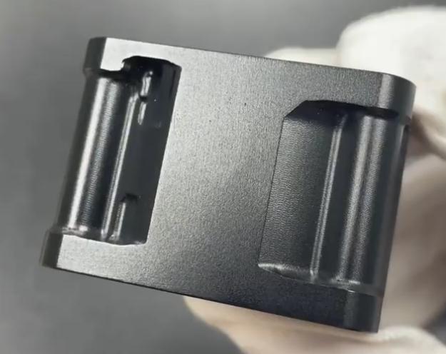
- Darker natural color, generally gray to dark gray or brown, depending on alloy and thickness.
Applicable alloys and materials
Hardcoat anodizing is mainly used for:
- Aluminum and aluminum alloys (6000, 5000, 2000, 7000 series, and some cast alloys) as specified in MIL-A-8625 or equivalent standards.
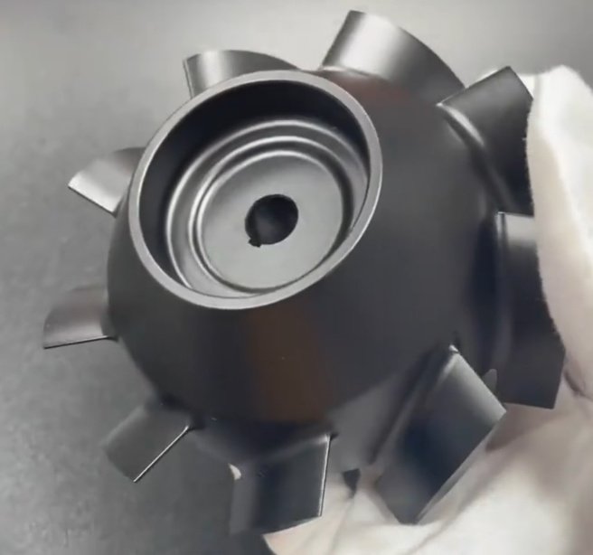
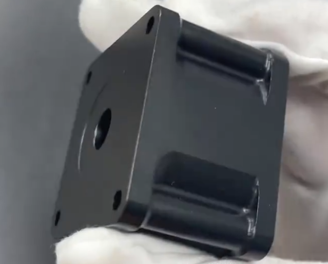
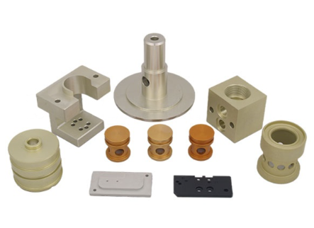
- Aluminum-based CNC machined parts such as housings, fixtures, valves, pistons, mechanical guides, and precision tooling.
Specific alloy composition influences achievable thickness, color uniformity, porosity, and risk of burning at sharp edges. High-copper or high-silicon alloys may produce darker, more variable finishes, while high-strength alloys can be more susceptible to fatigue strength reduction if not properly processed.
Process Parameters and Technical Characteristics
Hardcoat anodizing quality and consistency depend on multiple parameters that need to be precisely controlled. Understanding these parameters helps designers and process engineers make realistic specifications and select suitable suppliers.
Typical process parameters
The following ranges are typical for sulfuric acid-based hardcoat anodizing. Actual values depend on alloy, required thickness, and specific process chemistry.
| Parameter | Typical range / notes |
|---|---|
| Electrolyte base | Sulfuric acid solution |
| Acid concentration | ~150–240 g/L H₂SO₄ (approx. 10–18 wt%), process-dependent |
| Temperature | About -5 °C to +5 °C (23–41 °F), low temperature is key for hardness and thickness |
| Current density | ~2–6 A/dm² (18–55 A/ft²), sometimes higher for specific processes |
| Voltage | Typically up to 60–100 V, ramped during processing |
| Time | Commonly 20–90 minutes, depending on desired thickness and alloy |
| Thickness range | ~25–75 μm (0.001–0.003 in) is common; some processes go beyond this |
Coating structure and properties
The hardcoat layer consists of two main regions:
- A relatively thin, dense barrier layer at the metal interface that provides strong adhesion and corrosion resistance.
- A thicker, more porous outer layer with columnar oxide cells that can be sealed or impregnated with lubricants or dyes.
Key properties typically include:
- Hardness: approximately 400–600 HV or higher, depending on alloy and process.
- Coefficient of friction: can be significantly reduced when combined with PTFE or other lubricating impregnants.
- Dielectric strength: hardcoat layers can provide high electrical insulation until breakdown voltage is reached, useful for some electrical components.
- Thermal stability: aluminum oxide has high melting and softening temperatures, maintaining performance under elevated operating temperatures compared with bare aluminum surfaces.
Standards and specifications
Commonly referenced standards for hardcoat anodizing include:
- MIL-A-8625 (most notably Type III, Class 1 for non-dyed and Class 2 for dyed coatings).
- ISO and EN anodizing standards that define thickness classes, test methods, and performance criteria.
- Customer-specific or industry-specific specifications detailing exact thickness, sealing method, and test requirements.
Compliance with these standards influences process control, inspection, documentation, and quality assurance steps like destructive thickness measurements and salt spray testing.
Thickness, Growth Ratio, and Dimensional Tolerances
Dimensional control is a primary concern for CNC machined parts that will be hardcoat anodized. Because the anodic film is formed from the base metal, thickness growth is divided between penetration into the substrate and buildup above the original surface. This affects critical fits such as bores, shafts, threads, and sealing surfaces.
Coating growth ratio
For hardcoat anodizing, the growth behavior is often approximated by a 50/50 rule:
- About 50% of the nominal coating thickness penetrates into the base metal.
- About 50% builds up on the outside of the original surface.
For example, a 50 μm (0.002 in) hardcoat thickness typically results in approximately 25 μm (0.001 in) buildup on each external surface. Actual ratios can vary with alloy and process, but this approximation is widely used for design purposes.
Dimensional changes on different features
Dimensional impact is determined by geometry:
- External diameters and widths: increase by approximately 2 × (buildup thickness) across the feature.
- Internal diameters (bores, holes): decrease by approximately 2 × (buildup thickness) across the diameter.
- Flat-to-flat dimensions (e.g., keyways, slots): decrease by twice the buildup on each surface involved.
As a simple design rule, for a 50 μm nominal coating:
- External features grow by about 0.05–0.06 mm (0.002–0.0024 in) in overall size.
- Internal diameters shrink by about 0.05–0.06 mm (0.002–0.0024 in) in overall size.
Practical tolerance planning for CNC machined parts
To achieve functional fits after hardcoat anodizing, designers and machinists typically:
- Undersize external diameters and oversize internal diameters before anodizing, by an amount equal to the expected buildup.
- Consider a realistic tolerance band for coating thickness (for example ±5–10 μm) and translate that into a dimensional tolerance budget.
- Use post-anodize sizing only when necessary, recognizing that machining or grinding through the coating can reduce corrosion resistance locally.
As a reference, if a nominal hardcoat thickness of 40 μm is specified with a tolerance of ±10 μm, then buildup on each surface is approximately 20 ±5 μm. This means a possible external dimension change of 40 ±10 μm, which must be compatible with the required assembly clearance or interference.
Impact on tight tolerance features
When fits are in the range of a few micrometers, even normal variation in anodizing thickness becomes critical. Common strategies include:
- Masking high-precision mating surfaces to prevent coating and keep machined tolerances unchanged.
- Designing components so that hardcoat is located on non-critical areas while critical precision features are isolated or protected.
- Adding dedicated grinding or lapping operations after anodizing for specific surfaces, with acceptance that these surfaces will not benefit from full coating thickness.
- Loosening the dimensional tolerance slightly where possible and designing the functional requirement around the coated dimensions rather than the pre-anodize dimensions.
Masking Strategies for Hardcoat Anodizing
Masking controls which surfaces are anodized and protects features that must maintain base-metal dimensions or conductivity. Effective masking is vital in precision CNC machined parts, hydraulic components, and assemblies with sliding or interference fits.
Objectives of masking
Masking is typically used to:
- Maintain tight tolerances by preventing coating buildup on specific areas.
- Preserve metallic contact surfaces for electrical grounding or bonding.
- Protect threaded holes or fine pitch threads that may seize or distort after anodizing.
- Guard sealing surfaces that interact with elastomeric O-rings, metal seals, or glass-to-metal seals.
Common masking methods
Several techniques are used, sometimes in combination, to mask parts during hardcoat anodizing:
- Mechanical plugs and caps: reusable or disposable polymer plugs, caps, and stoppers inserted into holes or over external features. They are widely used for through-holes, internal threads, and bores where the coating is not desired.
- Tapes and adhesive films: specialized anodizing-resistant tapes applied to flat surfaces or simple contours. They must withstand the electrolyte, temperature, and agitation without lifting.
- Liquid masking compounds: brush-on or spray-on resists that cure to form a protective layer. Useful for irregular shapes or localized exclusion zones. These require careful application to achieve clean edges and avoid pinholes.
- Custom fixtures and masks: machined fixtures used to both hold the part and mask specific surfaces. Common in high-volume or highly complex parts, where repeatability and automation are important.
Design considerations for maskability
From a design standpoint, it is beneficial to:
- Provide accessible, well-defined boundaries between coated and uncoated regions, such as clear shoulders or chamfers to terminate the coating.
- Avoid extremely narrow recesses that are difficult to plug or tape effectively.
- Ensure adequate clearance around masked areas for fixtures and for solution flow to adjacent zones that require coating.
- Accept small dimensional transitions or coating edge lines where mask edges meet the anodized region.
Where possible, marking drawings clearly with “do not anodize” and “masking required” notes for specific surfaces or features makes it easier for the anodizer to implement a robust masking plan.
Finishing Operations After Hardcoat Anodizing
After hardcoat anodizing, parts may undergo additional finishing steps that tailor appearance, performance, or assembly characteristics. These operations must be selected and controlled to avoid impairing the function of the anodic layer.
Sealing
Sealing closes the pores of the anodic coating to improve corrosion resistance and, in some cases, modify hardness and friction. Common sealing methods include:
- Hot water or steam sealing: hydrating the aluminum oxide to form boehmite, which swells and closes pores. Effective for corrosion resistance but may slightly reduce surface hardness and wear resistance.
- Nickel acetate or other chemical seals: performed at elevated temperature, providing good corrosion resistance with controlled impact on mechanical properties.
- Cold sealing chemistries: proprietary solutions used in some production environments to achieve efficient sealing at lower temperatures.
For parts where maximum wear resistance is critical, sealing conditions are selected carefully. In some applications, partial or no sealing is specified to maintain maximum hardness, accepting reduced corrosion resistance or using external lubrication instead.
Impregnation with lubricants or dyes
The porous structure of the outer layer allows infiltration of functional substances. Common post-anodizing treatments include:
- PTFE or other solid lubricant impregnation: significantly reduces the coefficient of friction and improves sliding behavior. Typical in pistons, cylinders, guides, and moving mechanical assemblies.
- Dyeing: although hardcoat natural color is generally dark, dyes can be used to achieve black or other colors, especially in Type III Class 2 anodizing. Color uniformity is influenced by alloy and thickness.
- Special impregnations: in some cases, corrosion inhibitors or other functional substances can be incorporated into the pores for specific performance targets.
Impregnation steps occur before sealing is completed so that the pores remain accessible. Process sequencing and residence time must ensure adequate penetration and stable fixation of the impregnated material.
Mechanical finishing and machining after anodizing
Some components require mechanical operations after hardcoat anodizing:
- Precision grinding, honing, lapping, or superfinishing to achieve tight final dimensions or specific surface roughness on bearing surfaces.
- Light polishing or buffing for cosmetic adjustment of visible surfaces.
- Deburring operations limited to non-critical edges or masked areas.
Any machining that removes the anodic layer exposes bare aluminum and reduces corrosion and wear resistance in those locations. Therefore, post-anodize machining is usually limited to surfaces that are either protected by secondary coatings or do not require the benefits of hardcoat. In some designs, a deliberate compromise is made, trading local protection for high-precision fit.
Surface Roughness and Geometry after Hardcoat Anodizing
Hardcoat anodizing modifies both surface roughness and micro-geometry of CNC machined parts. This is particularly important for sealing, sliding, and optical applications.
Effect on surface roughness (Ra, Rz)
Typically, hardcoat anodizing increases surface roughness compared with the base machined finish. This is due to the columnar growth of oxide and microstructural influences of the alloy.
General tendencies include:
- A fine turned or milled surface may show a noticeable increase in Ra after hardcoat anodizing.
- Ground or polished surfaces maintain low Ra but may still experience an increase that must be accounted for in functional design.
- Sandblasted or bead-blasted surfaces exhibit the underlying texture, often enhanced by the oxide growth.
When a specific Ra is required in the final part, the pre-anodize finish should be appropriately finer to allow for this increase. In some cases, a post-anodize finishing step (such as controlled polishing) is specified for critical surfaces.
Edge definition and geometry changes
Hardcoat anodizing tends to round sharp edges slightly and can produce non-uniform thickness at corners or difficult-to-reach features. This is a result of electric field concentration and solution flow. For designers and machinists, the practical implications include:
- Sharp corners and knife edges are prone to higher local current density, which can lead to burning or excessive thickness. Chamfering or radiusing edges is recommended.
- Deep narrow grooves or blind holes may exhibit reduced thickness due to limited electrolyte access and lower local current density.
- Complex 3D geometries may have subtle thickness variations that affect critical fits unless carefully considered.

Corrosion and Wear Performance of Hardcoat Anodized Parts
Hardcoat anodizing is frequently chosen to improve durability in harsh service conditions. Understanding the relationship between coating thickness, sealing, and environment helps in specifying realistic requirements.
Corrosion resistance
Hardcoat anodized aluminum can provide excellent corrosion resistance in many environments, particularly when properly sealed. Important factors include:
- Coating thickness: thicker layers generally increase barrier protection and prolong time to corrosion onset.
- Sealing quality: properly sealed pores limit penetration of corrosive species such as chloride ions.
- Alloy composition: some alloys are more corrosion-resistant after anodizing than others; high-copper alloys may require extra care.
- Post-treatment environment: exposure to aggressive chemicals, extreme pH, or galvanic coupling with more noble metals may reduce service life if not accounted for in the system design.
Standard test methods such as neutral salt spray (NSS) are often specified in conjunction with thickness and sealing requirements to verify corrosion performance.
Wear and friction properties
The high hardness of the aluminum oxide layer enables significant improvements in wear resistance:
- Sliding wear: properly specified hardcoat can dramatically reduce wear of sliding pairs, especially when combined with lubrication or PTFE impregnation.
- Abrasive wear: the ceramic nature of the coating offers good resistance to abrasive particles in many applications.
- Adhesive wear: the oxide layer reduces metal-to-metal contact and lowers the tendency for galling and seizure.
When designing for wear performance, it is important to consider counterface material (such as steel, polymer, or another anodized part), lubrication conditions, applied pressure, and sliding speed. These parameters influence required coating thickness, finishing, and any additional treatments.
Design Guidelines for CNC Machined Parts to be Hardcoat Anodized
Integrating hardcoat anodizing considerations early in the design cycle can reduce rework and improve production reliability. The following guidelines support more robust CNC-machined designs.
Material selection and alloy choice
When selecting an aluminum alloy for hardcoat anodizing:
- Balance mechanical requirements (strength, stiffness) with anodizing behavior (color uniformity, hardness, corrosion response).
- Consult anodizer data for preferred alloys that consistently yield good hardcoat quality and uniform color.
- Consider that some high-strength alloys may experience a reduction in fatigue strength after anodizing. Design safety factors should reflect this.
Feature design and tolerance allocation
To achieve reliable results:
- Specify critical dimensions after anodizing wherever possible, and clearly indicate “dimensions apply after hardcoat anodize.”
- Allocate tolerances that accommodate coating thickness variation in addition to CNC machining variation.
- Use appropriate chamfers or radii on edges to avoid burning and improve coating uniformity.
- Group surfaces by functional requirement (e.g., sliding surface, sealing surface, cosmetic surface) and define different anodizing or masking treatments accordingly.
Threaded features and fasteners
Threads present specific demands:
- Internal threads may be masked to maintain fit and prevent thread interference, especially for fine pitches or critical preload conditions.
- External threads can be undersized before anodizing or masked depending on tolerance needs and service environment.
- For permanent assemblies, controlled anodizing on threads can be used to modify friction and locking behavior, but requires close coordination between designer and anodizer.
Pain points related to tolerances and fit
Common difficulties encountered when combining hardcoat anodizing with precision CNC machining include:
- Unexpected interference fits after anodizing due to underestimation of coating buildup or thickness variation.
- Distorted or seized threaded connections when threads are not masked or dimensioned for the coating thickness.
- Non-uniform coating thickness on complex geometries, causing local fit issues or inconsistent wear behavior.
- Rework of parts when tolerance stacks do not consider both machining and anodizing contributions, leading to scrap or additional finishing steps.
Addressing these issues requires precise communication of requirements, realistic tolerances, and early involvement of the anodizing supplier in design and process planning.
Quality Control, Inspection, and Documentation
Hardcoat anodizing quality must be verified and documented to ensure that CNC machined parts perform as intended in service. Quality control involves both in-process checks and final inspection steps.
Coating thickness measurement
Thickness is a key parameter and can be measured using several methods:
- Eddy current instruments: non-destructive measurement techniques suitable for many production parts. They require calibration and are generally more accurate on flat, accessible surfaces.
- Microscopic cross-section: destructive method used for process validation, test coupons, or when highest accuracy is required.
- Weight gain method: comparing part mass before and after anodizing in controlled situations, often used for process development rather than routine inspection.
Measurement locations and sampling frequency should be defined in the specification or quality plan, accounting for known variation on complex geometries.
Visual and dimensional inspection
Visual inspection checks for:
- Uniformity of color and appearance.
- Absence of burns, pits, stains, or poor adhesion.
- Clean transitions at masked boundaries and absence of residue from masking materials.
Dimensional inspection compares final dimensions after anodizing against the drawing requirements. For critical fits, dimensional inspection is often supplemented with functional gauges or assembly trials to verify proper performance in real mating conditions.
Performance testing
Depending on the application, additional tests may be specified:
- Corrosion resistance testing (e.g., salt spray, humidity exposure).
- Wear testing using standardized wear rigs or application-specific test benches.
- Adhesion and abrasion resistance evaluation using standard methods such as scratch tests or rubbing tests.
- Electrical insulation and breakdown voltage measurement for components where dielectric properties are critical.
Test results should be correlated with process parameters to maintain consistent performance across production lots.
Practical Collaboration Between CNC Shops and Anodizing Facilities
For CNC machined parts, hardcoat anodizing performance and dimensional accuracy depend not only on design, but also on the interaction between machining and anodizing processes.
Pre-anodizing preparation and cleanliness
Before hardcoat anodizing, parts must be clean and free of contaminants. Considerations include:
- Removal of cutting fluids, oils, and coolants that might interfere with uniform coating formation.
- Avoidance of markings or inks that cannot be removed in the pre-treatment steps.
- Control of surface damage from handling or fixturing that might be emphasized by the anodic layer.
Pre-treatment steps such as alkaline cleaning, etching, and desmutting are usually performed by the anodizing facility, but initial cleanliness from machining reduces variability and risk.
Communication of specifications
Clear and complete specifications are essential. Drawings and documentation should convey:
- Type of anodizing (e.g., “hardcoat anodize, Type III, Class 1, 40–50 μm”).
- Surfaces that require coating, and surfaces that must be masked or left uncoated.
- Dimensional requirements that apply after anodizing, including key fits and tolerances.
- Sealing requirements, dye or impregnation requirements, and any required post-treatments.
- Inspection and test requirements, including sampling plan and acceptance criteria.
Early technical discussions between the CNC shop, the anodizer, and the design engineer help avoid misunderstandings and ensure that all parties share realistic expectations for dimensional and cosmetic outcomes.
Summary
Hardcoat anodizing offers CNC machined aluminum parts a robust combination of wear resistance, corrosion protection, and dimensional stability when specified and executed properly. Because the coating grows both into and out from the base metal, designers and machinists must carefully account for thickness, buildup, and variation when defining tolerances and fits.
Masking allows selective protection of critical features, while finishing operations such as sealing, impregnation, and post-anodize machining tailor the final performance to the application. Robust quality control, including thickness measurement, visual inspection, and performance testing, ensures that the anodized components meet functional and dimensional requirements.
By integrating process knowledge, clear specification, and close collaboration between the CNC machining and anodizing operations, manufacturers can leverage hardcoat anodizing to produce durable, precise, and reliable aluminum components for demanding applications.
FAQ about Hardcoat Anodizing for CNC Machined Parts
How much will hardcoat anodizing change the dimensions of my CNC machined parts?
The dimensional change depends on the specified coating thickness. A useful approximation for hardcoat anodizing is that about half of the coating thickness builds up on the surface and half penetrates into the base metal. For example, if you specify a 50 μm (0.002 in) thick coating, expect roughly 25 μm (0.001 in) buildup on each surface. This means an external diameter could increase by approximately 50 μm (0.002 in), and an internal diameter could decrease by the same amount. Actual values vary with alloy and process, so you should consult your anodizing supplier and design critical fits using post-anodize dimensions, with appropriate tolerance for coating variation.
Which surfaces should be masked during hardcoat anodizing?
Masking is recommended for any surface where coating thickness and buildup cannot be tolerated or where bare metal is required. Typical examples include tight-tolerance bearing bores that cannot accept additional thickness, precision location surfaces used for alignment, fine pitch or critical threads where coating could cause interference or galling, electrical contact or grounding surfaces where conductivity must be maintained, and sealing surfaces that rely on a specific roughness and geometry. These surfaces should be clearly identified on the engineering drawing with notes such as “do not anodize” or “mask this surface,” allowing the anodizer to select suitable plugs, tapes, or custom masks.
