

CNC programming is the process of writing instructions that tell a CNC machine how to move and what actions to perform. These instructions are mainly written in two code families: G-code and M-code. Understanding both is essential for safe, accurate, and efficient CNC machining.
What Are G-Code and M-Code in CNC Programming?
In CNC programming, G-code and M-code work together to control a machine:
- G-code (preparatory functions) defines how the machine moves and interprets coordinates.
- M-code (miscellaneous functions) controls machine auxiliary actions such as spindle, coolant, and program stops.
Most CNC controls follow the ISO 6983 standard in principle, but each machine builder and control manufacturer can add or modify codes. For this reason, the meaning of some codes is controller-specific, while core motion codes remain similar across platforms.
Machine Coordinate Systems and Reference Points
CNC programs rely on numerical coordinates to describe positions and tool paths. Before writing or reading G-code, it is necessary to understand the coordinate systems and key reference points used on CNC machines.
Absolute and Incremental Coordinates
CNC controls support two primary coordinate modes:
- Absolute coordinates (G90): All positions are referenced to a fixed origin, usually the workpiece zero.
- Incremental coordinates (G91): Each movement is defined relative to the current position.
In absolute mode, a command such as G01 X50.0 Y20.0 moves the tool directly to the coordinates X=50.0, Y=20.0. In incremental mode, the same command moves the tool 50.0 units in X and 20.0 units in Y from its current position.
Machine Zero, Work Zero, and Tool Offsets
CNC machines distinguish between several coordinate origins:
Machine zero (G53) is the manufacturer-defined reference point. It is used for homing and machine calibration. Coordinates in this system are usually not used directly during part programming.
Work zero (G54–G59 and beyond) defines the origin for a specific part setup. The most commonly used work coordinate system is G54. Setting work zero aligns the drawing coordinate system with the physical part location on the machine table or chuck.
Tool length and radius offsets (e.g., H and D values in milling, T geometry and wear offsets in turning) compensate for the physical dimensions of the cutting tool. The program can reference an ideal tool tip position, and the CNC control shifts the actual tool according to the stored offset values.
Axis Conventions for Mills and Lathes
Typical axis definitions depend on machine type:
- 3-axis vertical mill: X (left-right), Y (front-back), Z (up-down).
- 2-axis slant-bed lathe: Z (spindle axis, along part length), X (radial direction toward or away from spindle centerline).
Rotary axes (A, B, C) represent rotation around X, Y, and Z respectively. These axes appear in 4-axis or 5-axis machines and are often combined with linear axes to achieve complex tool orientations.
Basic Structure of a CNC Program
CNC programs are text files built from lines called blocks. Each block usually contains one or more words, where each word starts with a letter followed by numbers. Proper structure helps the control parse commands reliably.
Program Format and Block Structure
A typical block can include:
- Block number (optional): N-word, such as
N010. - Preparatory function: G-word, such as
G00,G01,G02. - Coordinates: X, Y, Z (and possibly A, B, C).
- Feedrate: F-word, such as
F150.0. - Spindle speed: S-word, such as
S1200. - Tool call: T-word, such as
T0101on a lathe orT1on a mill. - Miscellaneous function: M-word, such as
M03,M08,M30.
Example block for a milling operation:
N100 G01 X25.0 Y40.0 Z-5.0 F200.0
Program structure usually includes:
Start / header: Safety line to set modal states (plane, units, coordinate mode), followed by tool selection and spindle setup.
Body: Sequences of motions and auxiliary commands to machine features.
End: Commands to stop the spindle, turn off coolant, and return the machine to a safe position, followed by program end and reset.
Modal and Non-Modal Commands
Many G and M codes are modal, meaning they remain active until another code in the same group overrides them. For example, if G01 (linear interpolation) is commanded, it stays in effect for subsequent motion blocks that specify new coordinates but no new G-code from that motion group.
Non-modal codes apply only to the block in which they appear. Examples include some canned cycle cancellations and certain control-specific functions.
Fundamental G-Code Categories and Their Functions
G-codes are organized into groups that control specific aspects of machine behavior. Each group typically allows only one active code at a time.
Motion and Interpolation G-Codes
Motion codes are the foundation of CNC programming, defining the path followed by the tool:
| G-Code | Typical Meaning | Usage Notes |
|---|---|---|
| G00 | Rapid positioning | Moves as fast as possible along shortest path; used for non-cutting moves. |
| G01 | Linear interpolation | Straight line cutting at programmed feedrate (F). |
| G02 | Circular interpolation, clockwise | Arc or circle movement; center defined by I, J, K or radius by R. |
| G03 | Circular interpolation, counterclockwise | Same as G02 but CCW direction. |
| G28 | Return to reference (home) position | Often used with intermediate point; always ensure safe path. |
| G53 | Machine coordinate system move | Non-modal, moves in machine coordinates, bypassing work offsets. |
For arcs using G02 and G03, typical parameters are:
- I, J, K: Center point coordinates relative to the start of the arc.
- R: Radius of the arc, where allowed by the control.
Controls typically require specification of the end point of the arc and either the center offset or the radius. Consistency of units and coordinate mode (G90 vs G91) is essential for correct arc geometry.
Coordinate System Selection and Units
G-codes also define which coordinate system and unit system the machine uses:
G54–G59 select work coordinate systems, each representing a specific work offset. Additional systems (e.g., G54.1 P1–P48) may be supported on advanced controls.
G20 selects inch units; G21 selects metric units.
Plane selection codes define the active interpolation plane, which affects the interpretation of G02/G03 and some cycles:
- G17: XY plane (common on mills).
- G18: ZX plane.
- G19: YZ plane.
Feed and Speed Related G-Codes
Feedrate and spindle behavior are governed by several codes and words:
F defines the feedrate. On mills, this is typically in units per minute (mm/min or in/min). On some lathes and specific controls, feed per revolution (G95) can be used instead of feed per minute (G94).
G94: Feed per minute mode.
G95: Feed per revolution mode (common in turning when synchronized with spindle speed).
Spindle speed is set with S followed by a numeric value in revolutions per minute (RPM) unless constant surface speed is enabled. Constant surface speed modes on lathes include:
- G96: Constant surface speed (CSS) mode, where S defines surface speed (e.g., m/min or ft/min).
- G97: Constant RPM mode, where S defines spindle RPM directly.
Positioning Modes: Absolute and Incremental
As noted earlier, coordinate interpretation is controlled by:
- G90: Absolute programming, coordinates measured from active work zero.
- G91: Incremental programming, coordinates measured from current position.
Some controls also use G90/G91 for cycle-related parameters, so reference to control documentation is important when mixing cycles and positioning modes.
Common M-Codes and Machine Control Functions
M-codes control actions like spindle start/stop, coolant, and program flow. Their meanings can vary between machine builders, so reference to the machine’s documentation is always required. The following codes are among the most commonly encountered.
Spindle Control M-Codes
Standard spindle control codes include:
- M03: Spindle on, clockwise rotation.
- M04: Spindle on, counterclockwise rotation.
- M05: Spindle stop.
When combined with an S-word and sometimes an optional range selection code, the control sets the spindle speed and direction accordingly. On many machines, M03 and M04 are modal; the spindle continues to run until M05 or a program end resets it.
Coolant, Tool Change, and Auxiliary M-Codes
Coolant control is typically performed with:
- M08: Coolant on (often flood coolant).
- M09: Coolant off.
Tool changes and magazine operations use codes such as:
- M06 (or M6): Tool change on many milling controls.
For lathes, the T-word itself may perform tool indexing, or a separate code may be used, depending on the turret system and control type.
Other auxiliary M-codes often include:
- M00: Program stop; machine waits until operator intervention.
- M01: Optional stop; executed only if optional stop switch is active.
- M30: Program end and rewind; resets modal states and returns to program start.
Modal Groups and Code Priority
Controls categorize G-codes in modal groups to avoid conflicts. Only one G-code per group can be active at a time. If two codes from the same group appear in a single block, the last one typically takes priority. Incorrect grouping can lead to errors or unintended behavior.
Typical Modal Groups
Although naming and numbering differ by control, common modal groups are:
- Motion group: G00, G01, G02, G03, and other motion-related codes.
- Plane selection group: G17, G18, G19.
- Units group: G20, G21.
- Absolute/incremental group: G90, G91.
- Feed mode group: G94, G95.
- Spindle speed mode group (lathe): G96, G97.
Understanding modal behavior helps prevent conflicts and reduces the number of repeated codes in programs, making them more concise and easier to read.
Basic Milling G-Code Programming
Milling machines typically use three or more axes and are suited to prismatic and free-form machining. Programs define tool paths, depths, and sequences to remove material from the workpiece.
Typical Milling Program Layout
A basic milling program often contains:
- Safety line and initial setup: Units, coordinate system, plane, and compensation resets.
- Tool selection and spindle setup: Tool call, spindle speed, direction, and coolant.
- Approach moves: Rapid moves to a safe approach position above the part.
- Cutting passes: G01/G02/G03 moves defining contours, pockets, or profiles.
- Retract and tool change: Return to safe height, optionally change tools.
- Program termination: Turn off spindle and coolant, go to home position, end program.
Example skeleton for a simple milling program:
%
O1000 (SIMPLE MILL PROGRAM)
G21 G17 G90 G40 G49 G80
G54
T1 M06
S1500 M03
M08
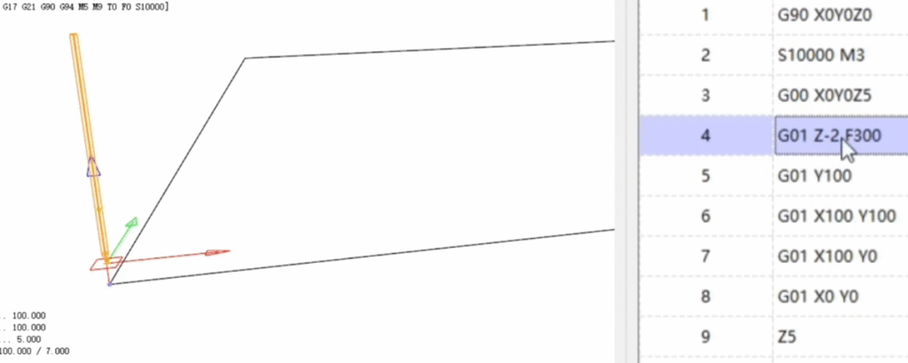
G00 X0 Y0 Z5.0
G01 Z-2.0 F120.0
G01 X50.0 Y0.0 F200.0
G01 X50.0 Y30.0
G01 X0.0 Y30.0
G01 X0.0 Y0.0
G00 Z50.0
M09
M05
G28 G91 Z0
G90
M30
%
Tool Path Planning and Safe Movements
Safe milling programs must respect:
- Clearance heights above clamps, fixtures, and stock.
- Minimum distances between rapid moves and part geometry.
- Gradual engagement of tools using lead-in moves and appropriate depths of cut.
Many programmers define a standard clearance plane, such as Z=50.0 mm above the workpiece, and return to this plane between operations to avoid collisions.
Basic Turning G-Code Programming
Turning involves rotating the workpiece and moving a stationary or linearly moving tool along X and Z axes. Programs define profile paths, facing, roughing, and finishing passes.
Lathe Coordinate Concepts
On typical 2-axis lathes:
- Z axis is aligned with the spindle: positive away from the chuck, negative toward the chuck.
- X axis is radial: X0 corresponds to the spindle centerline.
Many controls program X as the diameter value instead of radius. For example, if the cutting point is 10 mm from centerline, X20.0 may represent the diameter. Confirming whether the control uses diameter or radius programming is important for consistent part dimensions.
Typical Turning Program Layout
A basic lathe program often includes:
- Initial safety line: Units, mode, and cancellation of compensation and cycles.
- Work offset selection and tool call.
- Spindle start and optional constant surface speed configuration.
- Facing operation to clean the front surface.
- Roughing and finishing passes along the profile.
- Retract to a safe position and program end.
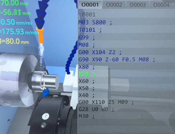
Example skeleton for a simple turning program (diameter programming assumed):
%


O2000 (SIMPLE TURN PROGRAM)


G21 G18 G90 G40 G80


G54


T0101


G97 S800 M03


M08


G00 X60.0 Z2.0


G01 Z0.0 F0.3


G01 X0.0


G00 X60.0 Z2.0


G00 Z2.0


M09


M05


G28 U0 W0


M30


%
Coordinate Modes, Planes, and Units in Detail
Correct configuration of coordinate modes prevents common programming errors and simplifies code reuse across machines and setups.
Units: Metric and Imperial
G20 selects inches, and G21 selects millimeters. These codes are modal and typically appear in the program header. Mixing units within a program is rarely advisable. Tool data, offsets, and drawings must be consistent with the selected unit system.
Interpolation Planes and Their Effects
Plane selection affects circular interpolation and many canned cycles:
- G17 (XY plane): Arcs defined by X, Y coordinates with I and J center offsets.
- G18 (ZX plane): Arcs defined by X, Z coordinates with I and K center offsets.
- G19 (YZ plane): Arcs defined by Y, Z coordinates with J and K center offsets.
For example, on a vertical mill, pocket milling in the XY plane uses G17 with G02/G03 arcs defined by X, Y, and I, J. When working on the end of a rotating part on a lathe's C-axis with live tooling, G18 might be active, and arcs are defined differently.
Absolute vs Incremental Strategies
Programmers may combine absolute and incremental blocks to simplify complex tool paths. Absolute coordinates align with drawing dimensions, while short incremental moves can be convenient for repeated relative steps, such as peck drilling or small finishing passes. Careful use of G90 and G91 reduces the chance of mixing coordinate systems unintentionally.
Tool Compensation and Offsets
Tool offsets correct for differences in tool length, diameter, and wear, allowing programs to reference theoretical geometry while machining with real tools.
Tool Length Compensation on Mills
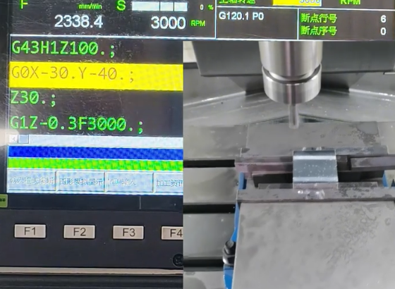
Tool length compensation shifts the Z-axis position to account for the physical distance between the spindle gauge line and the tool tip. Common codes include:
- G43: Tool length compensation, positive (most common).
- Hxx: Tool length offset register number.
Typical sequence:
T1 M06


G00 G43 Z50.0 H01
This activates the length offset stored in register 01 and moves to Z50.0 in the compensated coordinate system.
Cutter Radius Compensation
Cutter radius compensation (CRC) allows programming of part geometry by the theoretical tool centerline without manually offsetting for tool radius. Codes commonly used are:
- G41: Cutter compensation left (tool path shifted left of programmed path relative to cutting direction).
- G42: Cutter compensation right.
- G40: Cancel cutter compensation.
CRC requires lead-in and lead-out moves to allow the control to shift the tool path smoothly. Inadequate lead moves can lead to alarms or unexpected tool paths, so compensation is usually applied in straight-line segments before cutting the actual profile.
Tool Geometry and Wear Offsets on Lathes
Lathe tools are managed using:
- Geometry offsets: Define the theoretical tool nose position relative to the turret mounting face.
- Wear offsets: Small adjustments to fine-tune tool nose position and compensate for tool wear.
T-words often combine geometry and wear offset indices, such as T0101, indicating tool 1 with geometry offset 01 and wear offset 01. Many controls also support tool nose radius compensation, which requires specification of tool orientation and nose radius values in the tool data.
Feeds, Speeds, and Depth of Cut
Accurate feed and speed programming impacts tool life, surface finish, and machining time. Although specific values depend on material, tooling, and machine capability, CNC programs must define feeds and speeds explicitly or activate appropriate automatic control modes.
Feedrate Programming
Feedrate is specified by the F-word. On milling machines, feed per minute (G94) is common. For example, F250.0 indicates 250 mm/min in metric or 250 in/min in inch mode.
On lathes, feed per revolution (G95) is widely used. The feedrate is specified in mm/rev or in/rev, ensuring constant chip load despite changes in spindle speed when using constant surface speed.
Spindle Speed and Constant Surface Speed
Constant RPM mode (G97) keeps spindle speed fixed at the programmed S value. Constant surface speed mode (G96) adjusts RPM automatically to maintain a target surface speed at the cutting point. This is particularly useful in turning, where the diameter changes as material is removed.
When using G96, a maximum spindle speed limit is often set using an additional parameter or control-specific code to prevent excessively high RPM at small diameters.
Depth of Cut and Stepovers
Depth of cut refers to the thickness of material removed in one pass, often programmed as a change in Z for axial depth or X for radial depth on lathes. Stepover describes the lateral distance between adjacent passes in milling, usually programmed as an X or Y increment between tool paths.
Programs typically combine multiple roughing passes with larger depths of cut, followed by one or more finishing passes with smaller depths and refined feedrates to achieve required tolerances and surface quality.
Canned Cycles for Drilling and Boring
Canned cycles simplify repetitive operations like drilling, tapping, and boring by bundling common motion sequences into single G-code commands. The exact syntax and behavior vary by control, but the overall idea is consistent: fewer lines of code for repeated patterns.
Common Milling Drilling Cycles
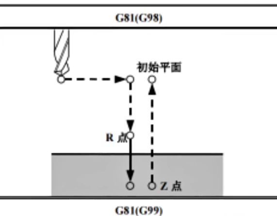
Typical cycles on milling machines include:
- G81: Simple drilling cycle.
- G82: Drilling with dwell at bottom.
- G83: Peck drilling to break chips and reduce heat.
A basic drilling cycle may specify:
- R: Retract plane (rapid move level before and after each hole).
- Z: Final depth of the hole.
- F: Feedrate for the drilling movement.
- P: Dwell time (for cycles that support dwell).
Example of a simple G81 cycle:
G90 G81 X20.0 Y20.0 Z-10.0 R2.0 F150.0


X40.0 Y20.0


X60.0 Y20.0


G80
This drills three holes at the specified coordinates, all with the same depth and feed, then cancels the cycle with G80.
Turning Canned Cycles
Turning controls provide cycles for facing, roughing, finishing, threading, and grooving. Examples include (control-dependent):
- Facing cycles that automatically generate radial passes across the face of the part.
- Longitudinal roughing cycles that follow a series of programmed profile points and automatically generate multiple depth passes.
- Threading cycles that synchronize feed with spindle rotation to cut external or internal threads.
Each cycle has specific parameters for depth of cut, finishing allowance, retract, and other behavior. Programs often use cycles to shorten code and make it easier to adjust machining strategies.
Program Flow, Subprograms, and Reuse
CNC programs often contain repeated features such as patterns of holes, symmetrical pockets, or repeating profiles. Subprograms and program control commands allow reuse of code blocks for efficiency.
Program Flow Control
Program flow can be managed by:
- Unconditional stops (M00) for inspection or manual intervention.
- Optional stops (M01) controlled by an operator switch.
- Multiple program numbers with selective execution based on operator choice.
Some controls also support conditional logic and macro variables, enabling more flexible automation and parametric programming, but the basic program flow is usually linear from start to end.
Subprogram Calls and Repeats
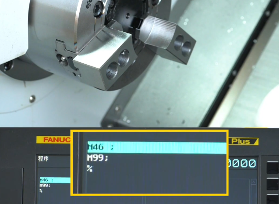
Subprograms encapsulate sequences of blocks that can be called multiple times with different parameters or in different locations. Common commands (control-dependent) include:
- M98: Call subprogram, often with an address for program number and repeat count.
- M99: Subprogram end and return.
Example:
M98 P3000 L4
This might call subprogram O3000 four times. Inside subprogram O3000, the tool path for one instance of a pattern (e.g., a hole) is defined. Subprograms can be especially effective when combined with work offsets or coordinate shifts for arrays of identical features.
Common Issues and Safety Considerations
Accurate and safe CNC machining programming requires attention to details that go beyond simply writing correct G and M codes. Certain pitfalls frequently cause issues for less experienced programmers.
Typical Pain Points in CNC Programming
Common difficulties include:
- Misunderstanding modal behavior, leading to incorrect reuse of motion modes or feed modes across blocks.
- Incorrect work offsets, causing parts to be machined at the wrong location or orientation.
- Omitting clearance moves, resulting in unexpected collisions during rapid positioning.
- Mixing up absolute and incremental coordinates, particularly inside canned cycles.
- Using wrong units (G20 vs G21) relative to tool data and drawings.
Safe Setup and Dry Runs
To reduce risk, many shops enforce standard practices:
- Verify tool offsets and work offsets before running new programs.
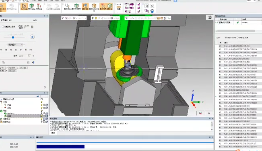
- Use graphic simulation on the control or CAM software to visualize tool paths.
- Run the program in single-block or dry-run mode above the part to confirm clearances.
- Use reduced feed override for the first part to detect any unexpected tool motions.
Documentation of programs, including comments describing operations and tool usage, helps operators understand the process and reduces errors during setup and operation.
| Aspect | G-Code | M-Code |
|---|---|---|
| Primary function | Defines motion, coordinate modes, cycles | Controls spindle, coolant, tool change, program flow |
| Modal behavior | Many G-codes are modal in groups | Many M-codes are modal (spindle, coolant), some non-modal |
| Examples | G00, G01, G02, G17, G54, G90 | M03, M05, M06, M08, M09, M30 |
| Standardization | Relatively standardized for basic motion | More variation across machine builders |
| Impact on tool path | Directly affects tool position and trajectory | Affects auxiliary systems and program sequencing |
FAQ about CNC G-Code and M-Code
What is the main difference between G-code and M-code?
G-code controls motion and machining modes, such as linear and circular moves, drilling cycles, and coordinate systems. M-code controls auxiliary machine functions, such as spindle start/stop, coolant on/off, tool changes, and program stops. Both types of codes are combined in program blocks to define complete machine behavior.
Do all CNC machines use the same G-codes and M-codes?
Most CNC controls share a common core set of G-codes and M-codes for basic functions like G00, G01, G02, G03, G81, M03, M05, and M30. However, code behavior and availability can vary across manufacturers and control models, especially for specialized functions such as probing, advanced cycles, or automation. It is essential to consult the specific machine and control manual to confirm supported codes and exact operation.
Is it necessary to learn manual G-code if I use CAM software?
CAM software can automatically generate G-code, but understanding manual G-code is highly beneficial. It helps in reading and verifying programs, making quick edits at the machine, adjusting feeds, speeds, or coordinates, and diagnosing errors or alarms. Many shops expect programmers and operators to be able to interpret and modify G-code even if most code originates from CAM systems.
How can I practice CNC programming without a physical machine?
You can practice CNC programming using simulation software or control emulators that run on a computer. These tools allow you to write, load, and simulate G-code, visualize tool paths, and check for basic errors without risk of damaging equipment. Many training platforms, control manufacturers, and CAM vendors provide simulation environments suitable for learning and practice.
