
CNC lathe machining, often referred to as CNC turning, is a subtractive manufacturing process that uses computer numerical control (CNC) to rotate a workpiece while a cutting tool removes material to create cylindrical or axisymmetric parts. It is widely used for shafts, bushings, fittings, fasteners, hydraulic components and many other precise rotational parts in metal and engineering plastics.
Fundamentals of CNC Lathe Machining
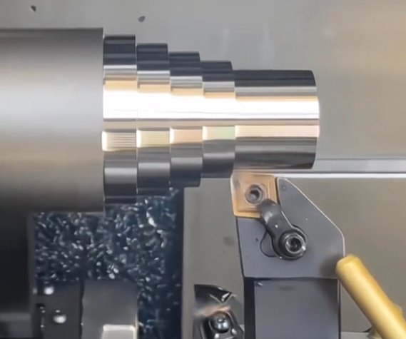
CNC lathe machining is based on the principle of relative motion between a rotating workpiece and a stationary or controlled cutting tool. The workpiece is clamped in the spindle and rotated around its main axis, while the tool moves along defined axes to generate the required geometry.
Unlike milling, where the tool rotates and the workpiece typically remains stationary or moves linearly, in turning the workpiece rotation generates the cutting speed. This makes CNC lathes especially efficient for parts where most features are concentric with a central axis.
Essential features of CNC lathe machining include:
- Computer-controlled motion along multiple axes
- High repeatability of dimensional accuracy
- Capability to produce complex profiles and threads
- Suitability for prototype, small batch and mass production
Main Components of a CNC Lathe
A CNC lathe consists of several mechanical and electronic subsystems that work together to perform turning operations with precision and consistency. Understanding these components helps in selecting machines, planning processes and troubleshooting.
| Component | Function |
|---|---|
| Bed | Main structural base providing rigidity, supporting slides and headstock, ensuring alignment. |
| Headstock | Houses the spindle, drive motor, gear or belt transmission and spindle orientation system. |
| Spindle | Rotating shaft that holds the chuck or collet and imparts rotation to the workpiece. |
| Chuck / Collet | Workholding device clamping the part; chucks handle varied diameters, collets excel at precision and repeatability. |
| Turret / Tool Post | Holds multiple tools and indexes them into position under CNC control for automatic tool changes. |
| Carriage and Cross Slide | Provide linear motion along Z (axial) and X (radial) axes for turning, facing and profiling. |
| Tailstock (if equipped) | Supports long workpieces with a live center or holds drills and reamers for axial operations. |
| Guideways | Precision surfaces or linear guides that constrain motion of the carriage and turret. |
| CNC Control | Numerical control unit that interprets programs, controls axis motion, spindle, coolant and auxiliary functions. |
| Servo Drives and Motors | Provide accurate and responsive motion for each axis and spindle orientation. |
| Coolant System | Delivers cutting fluid to reduce heat, improve chip evacuation and enhance surface finish. |
| Chip Conveyor | Removes chips from the cutting area, maintaining process stability and reducing manual handling. |
| Enclosure and Safety Guards | Contain chips and coolant, protect the operator and help control noise. |
Axes and Motion in CNC Lathe Machining
Typical CNC lathes use orthogonal linear axes and sometimes additional rotary or linear axes to perform complex operations.
Basic axis configuration includes:
- X-axis: Radial movement toward and away from the spindle centerline, controlling part diameter.
- Z-axis: Axial movement parallel to the spindle centerline, controlling part length and axial features.
Many CNC lathes and turning centers add:
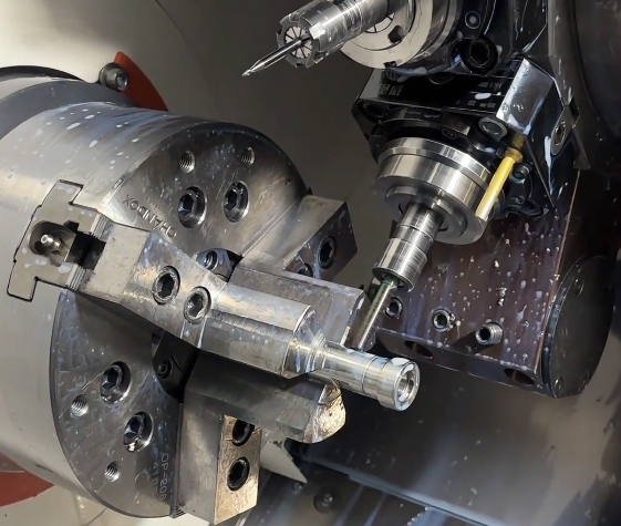
C-axis: Allows the spindle to be indexed or interpolated as a controllable axis. C-axis enables angular positioning and milling of flats, keyways, and holes around the circumference when combined with live tooling.
Some machines also incorporate Y-axis (off-centerline tool motion for more complex milling features) and additional sub-spindle axes for part transfer and back-side machining. These extended axes expand the range of features that can be produced in a single setup.
Common CNC Lathe Machining Operations
CNC lathes perform a wide range of operations by combining controlled tool paths with appropriate tooling. The primary goal is to convert raw stock into finished parts with specified dimensions, profiles and surface qualities.
1. Facing
Facing produces a flat surface at the end of a workpiece, perpendicular to the axis. The tool moves radially from the outer diameter toward the center while the workpiece rotates. Facing establishes a reference surface for subsequent operations and can control overall part length.
2. Straight Turning and Profiling
Straight turning reduces the external diameter over a specified length. Profiling uses controlled X and Z motions to generate contours such as tapers, radii, grooves and complex blended shapes. CNC control enables precise replication of intricate profiles from program data.
3. Boring and Internal Turning
Boring enlarges or finishes internal diameters using boring bars or internal turning tools. Internal turning operations can generate cylindrical bores, internal tapers, grooves and reliefs. Tool overhang and vibration control are important considerations to maintain accuracy and surface quality.
4. Drilling, Reaming and Tapping
With axial tools mounted in the turret or tailstock, CNC lathes can drill, ream and tap holes on the centerline. For machines equipped with C-axis and live tooling, off-center drilling and tapping are also possible. Coordinated spindle and feed control ensures accurate hole depth and thread pitch.
5. Grooving and Parting-Off
Grooving tools create recesses, snap-ring grooves, sealing grooves and reliefs on external or internal surfaces. Parting-off (cut-off) uses a narrow, rigid tool to separate finished parts from bar stock. Control of feed, tool geometry and coolant supply is important to avoid tool breakage and ensure clean separation.
6. Thread Cutting
Threads can be generated by single-point threading tools synchronized with spindle rotation, or by thread rolling and tapping tools. CNC control synchronizes tool feed with spindle speed to match the specified pitch. Internal and external metric, imperial and special threads are achievable, including tapered threads and multi-start threads.
7. Knurling
Knurling tools displace material to form regular patterns on cylindrical surfaces, improving grip and appearance. Although not strictly a cutting operation, it is commonly performed on lathes. Proper tool selection and pressure control are necessary to prevent excessive load on the spindle and workpiece.
Types of CNC Lathes and Turning Centers
Different CNC lathe configurations are optimized for specific ranges of part sizes, complexity and production volumes. Machine selection is guided by workpiece geometry, tolerances, material and required throughput.
| Machine Type | Typical Features | Typical Applications |
|---|---|---|
| 2-Axis CNC Lathe | X and Z axes, turret, manual or automatic chuck, tailstock optional. | General turning, shafts, bushings, flanges for low to medium complexity parts. |
| CNC Turning Center | Enclosed machine, automatic tool changer turret, higher power spindle, often bar feeder compatibility. | Production turning with short cycle times and frequent tool changes. |
| C-axis Lathe with Live Tooling | Rotary tools in turret, C-axis spindle control, sometimes Y-axis. | Complex parts requiring drilling, milling and slotting in a single setup. |
| Sub-Spindle Lathe | Main and secondary spindle, part transfer between spindles. | Complete machining of both ends of a part without manual repositioning. |
| Swiss-Type (Sliding Headstock) Lathe | Sliding headstock, guide bushing, often multiple tool stations and live tools. | Long, slender precision components with tight tolerances, often from bar stock. |
| Vertical CNC Lathe | Vertical spindle orientation, large faceplate or chuck, heavy-duty construction. | Large diameter, heavy workpieces such as rings, housings and disks. |
Materials Machined on CNC Lathes
CNC lathe machining is versatile in terms of workpiece materials. The cutting parameters, tool selection and coolant strategy are adjusted based on material properties such as hardness, toughness, thermal conductivity and tendency to work-harden.
Common categories include:
Carbon and alloy steels: From low-carbon structural steels to high-strength alloy steels used in automotive, mechanical and energy components. Selection of tool grades and cutting speeds must account for toughness and hardenability.
Stainless steels: Austenitic, martensitic and duplex stainless steels require appropriate cutting speeds, chip-breaking geometries and robust coolant delivery to control work-hardening and maintain tool life.
Aluminum and aluminum alloys: Good machinability and high cutting speeds are possible. Control of built-up edge and chip evacuation is important for surface finish and dimensional stability.
Copper and brass: Free-cutting brass machines easily with excellent surface finish. Copper requires attention to soft material behavior and chip control.
Cast irons: Gray, ductile and compacted graphite iron exhibit different machining behaviors. Tool selection focuses on wear resistance and edge strength to handle abrasive carbides within the microstructure.
Titanium and nickel-based alloys: Usually machined with lower cutting speeds, high-performance carbide or advanced tool materials and adequate coolant to manage heat and maintain dimensional accuracy.
Engineering plastics: Materials such as POM, PEEK, PTFE and nylon are turned with high rake tools and sharp edges. Considerations include thermal expansion, dimensional stability and potential for burr formation.
Key Process Parameters in CNC Lathe Machining
Controlling process parameters is essential for achieving desired accuracy, surface quality, productivity and tool life. The most critical parameters are cutting speed, feed rate, depth of cut and spindle speed.
Cutting Speed
Cutting speed (v) is the surface speed at the workpiece diameter and is typically expressed in m/min or sfm (surface feet per minute). It depends on material machinability, tool material and required tool life. Spindle speed (n) in rpm relates to cutting speed through the formula:
v = (π × D × n) / 1000 (for v in m/min, D in mm, n in rpm)
As diameter changes during turning, constant surface speed control can be used to maintain optimal cutting conditions by dynamically adjusting spindle speed.
Feed Rate
Feed rate (f) determines the distance the tool advances per revolution of the workpiece, usually in mm/rev or in/rev. It influences surface roughness, cutting forces and chip thickness. Lower feed rates generally improve surface finish but increase machining time. Roughing passes typically use higher feeds than finishing passes.
Depth of Cut
Depth of cut (ap) defines how much material is removed in one radial pass. Larger depths of cut increase material removal rate but raise cutting forces and tool load. Roughing operations may use relatively large depth of cut for efficiency, whereas finishing passes use smaller depths to achieve required accuracy and surface quality.
Spindle Speed
Spindle speed (n) in rpm is selected based on cutting speed and workpiece diameter. CNC controls can maintain a constant surface speed by continuously adjusting rpm as the tool moves to different diameters. Maximum spindle speed is limited by machine capabilities, workholding security and workpiece balance.
Coolant and Lubrication
Coolant application reduces cutting temperature, improves chip evacuation and extends tool life. Different strategies include flood coolant, high-pressure coolant and minimum quantity lubrication (MQL). For certain materials and operations, dry cutting may be feasible, but heat control and chip evacuation must still be addressed.
Tooling for CNC Lathe Machining
Tooling is central to CNC lathe machining performance. Modern lathes predominantly use indexable insert tooling combined with toolholders that provide repeatable positioning and rigidity.
Tool Types
Common turning tool categories include:
External turning tools: For OD turning, profiling and facing. They are selected based on geometry (rake, clearance), insert shape and nose radius.
Boring bars: For internal turning and boring. Stiffness and overhang ratio are critical factors to avoid vibration.
Grooving and parting tools: Narrow tools optimized for radial cutting and chip control in confined spaces.
Threading tools: Single-point tools with profiles matching thread form, used in conjunction with synchronized spindle control.
Drills, reamers and taps: For axial hole generation, finishing and threading. On live-tool lathes, these can also be used off-center.
Tool Materials and Coatings
Tool material selection is based on workpiece material, cutting parameters and required tool life. Common tool materials include:
Cemented carbide: Widely used due to its balance of hardness and toughness. Available in numerous grades tailored to steel, stainless steel, cast iron and non-ferrous materials.
Cermet: Ceramic-metal composites providing good wear resistance and surface finish for finishing operations, primarily in steels.
Ceramics: High-speed capability and wear resistance, mainly for cast iron and high-temperature alloys under stable conditions.
Cubic boron nitride (CBN): Suited for hardened steels, enabling hard turning as an alternative to grinding in some applications.
Polycrystalline diamond (PCD): For non-ferrous metals and abrasive composites, offering long tool life and excellent surface finish.
Coatings such as TiN, TiCN, TiAlN and AlTiN enhance wear resistance, reduce friction and help manage temperature at the cutting edge.
Tool Geometry and Chip Control
Tool geometry, including rake angle, clearance angle and nose radius, influences cutting forces, chip formation and surface finish. Chipbreakers on inserts are designed to control chip curling and breakage, improving evacuation and reducing the risk of chip entanglement.
Proper chip control is especially important in continuous turning operations on ductile materials, where long, continuous chips can interfere with the cutting process and affect surface quality.
CNC Programming for Lathe Machining
CNC lathe machining is driven by programs written in a CNC language, typically G-code. The program specifies tool motions, spindle speeds, feeds, tool changes and auxiliary functions.
Basic Programming Concepts
Core concepts include:
Coordinate systems: The machine coordinate system is defined by the manufacturer. Work coordinate systems (e.g., G54–G59) establish part zero locations for programming convenience.
Absolute and incremental programming: Positions can be specified with respect to a fixed origin (absolute) or relative to the previous position (incremental).
Interpolation: Linear (G01) and circular (G02/G03) interpolation commands define tool paths for straight lines and arcs.
Canned cycles: Predefined routines for common operations such as rough turning, finishing, drilling and threading simplify programming and reduce code length.
Programming Workflow
Typical programming workflow involves:
Reading the part drawing and defining datums and tolerances.
Selecting tools and holders, and assigning tool numbers and offsets.
Planning machining operations (roughing, semi-finishing, finishing, threading, grooving).
Calculating cutting data (speeds, feeds, depths of cut).
Writing or generating G-code manually or using CAM software.
Simulating toolpaths to verify absence of collisions and check motion logic.
Running a trial on the machine with appropriate safety checks and adjustments.
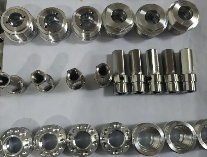
Dimensional Accuracy and Tolerances
CNC lathe machining can achieve tight dimensional tolerances when machines are properly maintained and processes are well controlled. The achievable tolerance depends on machine rigidity, thermal stability, tooling, measurement methods and part geometry.
Typical achievable tolerances for many industrial CNC lathes, under controlled conditions, are in the range of ±0.01 mm or better for common features. For short parts on precision machines, even tighter tolerances are possible, especially in stable environments and with in-process measurement.
Factors affecting accuracy include:
Machine condition: Wear in guideways, ball screws and spindle bearings.
Thermal effects: Heat generated by spindle, drives and ambient changes can cause expansion, influencing dimensions.
Workholding: Chucking force, part deformation and runout affect roundness and concentricity.
Tool wear: Progressive wear shifts effective cutting edge position and can alter dimension and surface finish.
Compensation functions in the CNC, such as tool offsets, wear compensation and thermal compensation, help maintain dimensional consistency over production runs.
Surface Finish in CNC Lathe Machining
Surface finish is a key quality attribute in turned parts, affecting performance such as sealing, fatigue strength and friction. Surface roughness is influenced by tool nose radius, feed rate, cutting speed, tool condition and material properties.
For many metals, fine finishing passes with low feed and small depth of cut, combined with sharp tools and stable cutting conditions, produce smooth surfaces suitable for sealing surfaces, bearing journals and functional fits. Roughness values (Ra) in the low micrometer or sub-micrometer range are achievable with optimized setups.
Where necessary, subsequent processes such as grinding, honing or polishing can further improve surface finish and dimensional accuracy beyond what is achieved by turning alone.
Workholding and Setup Considerations
Secure and accurate workholding is essential for reliable CNC lathe machining. Improper clamping can cause runout, vibration, deformation and dimensional inconsistencies.
Common workholding methods include:
Three-jaw self-centering chucks: Widely used for round stock, providing fast setup and moderate accuracy.
Four-jaw independent chucks: Allow adjustment of each jaw individually for irregular shapes or eccentric features.
Collet chucks: Offer high concentricity and repeatability for bar work and repetitive small parts.
Mandrels and arbors: Used for holding internal diameters when machining external features.
Tailstock support: Live centers or steady rests support long parts to prevent deflection during machining.
Setup involves aligning the workpiece, verifying clamping force, ensuring adequate tool clearance and establishing work coordinate systems. For bar-fed machines, bar feeders and bar pullers enable continuous production with minimal manual intervention.
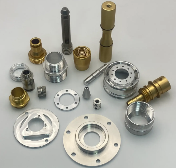
Typical Industrial Applications of CNC Lathe Machining
CNC lathe machining is integral to many manufacturing sectors due to its capability to produce precise rotational parts efficiently and consistently.
Representative application areas include:
Automotive: Shafts, pins, hubs, flanges, piston rods, fasteners and gearbox components.
Aerospace: Landing gear pins, bushings, hydraulic fittings, actuators and engine hardware.
Hydraulics and pneumatics: Cylinders, valve bodies, couplings, adapters and connectors.
Energy and power transmission: Turbine components, couplings, sleeves and bearing housings.
Medical and dental: Implants, surgical instruments, dental components and precision bushings, often with small diameters and tight tolerances.
General mechanical engineering: Rollers, spindles, threaded components, spacers and structural fasteners.
In many of these areas, CNC lathes are integrated into automated production cells, sometimes combined with robots, measurement systems and other machine tools to streamline production workflows.
Quality Control and Inspection in CNC Lathe Machining
To ensure that turned parts meet specifications, systematic inspection and quality control procedures are applied. Measurement is conducted both on the shop floor and in dedicated inspection areas, depending on tolerance requirements and part criticality.
Common inspection methods include:
Handheld instruments: Vernier calipers, micrometers, bore gauges and depth gauges for routine dimensional checks.
Comparators and gages: Plug gauges, ring gauges and thread gauges for fast go/no-go verification of critical features.
Coordinate Measuring Machines (CMM): For complex geometries and tight tolerances, providing detailed dimensional reports.
Surface roughness testers: Contact or non-contact equipment to quantify roughness parameters such as Ra and Rz.
Roundness and cylindricity testers: Specialized instruments for assessing rotational symmetry and form accuracy.
In-process gauging and tool monitoring can be integrated with CNC controls to detect deviations early, trigger tool changes or adjust offsets automatically, helping maintain stable quality during extended production runs.
FAQ about CNC Lathe Machining
What is CNC lathe machining?
CNC lathe machining is a manufacturing process where a computer-controlled lathe rotates a workpiece while cutting tools shape it into precise cylindrical or round components.
What is the difference between CNC lathe machining and CNC milling?
CNC lathe machining rotates the workpiece while milling rotates the cutting tool; lathes are best for cylindrical shapes, while milling handles flat or complex surfaces.
What are the advantages of CNC lathe machining?
Key advantages are high precision, consistent quality, fast production speed, material versatility, and reduced human error.
Is CNC lathe machining suitable for mass production?
Yes, CNC lathes are highly efficient for both prototype and high-volume production due to automation and repeatability.
