
CNC machining plays a critical role in modern manufacturing by producing highly precise components used in industries such as aerospace, automotive, medical devices, electronics, and industrial machinery. One of the most important technical aspects of CNC manufacturing is machining tolerance. Understanding CNC tolerance standards allows engineers, designers, and manufacturers to ensure parts function properly while maintaining cost-effective production.
This guide explains CNC machining tolerances in detail, including common standards, tolerance classifications, influencing factors, and practical recommendations for selecting the right tolerances for your parts.
What Is CNC Machining Tolerance?
CNC machining tolerance refers to the permissible deviation from the nominal dimension specified in a design drawing. Because no manufacturing process can achieve perfectly exact dimensions, tolerances define the acceptable range within which a part dimension can vary.
For example, if a component is designed with a dimension of 50 mm ±0.05 mm, the final manufactured part must fall between 49.95 mm and 50.05 mm.
Tolerance specifications are essential because they ensure:
- Proper fit between mating components
- Reliable mechanical performance
- Consistency in mass production
- Reduced assembly issues
- Controlled manufacturing costs
Without clearly defined tolerances, parts produced by different manufacturers or batches may not fit together properly.
Why Tolerances Are Important in CNC Machining
Tolerance control directly affects product functionality, quality, and manufacturing cost. In mechanical assemblies, components interact with each other through clearances, interference fits, or transitional fits. If tolerances are too loose, the assembly may experience excessive movement or vibration. If tolerances are too tight, parts may not assemble at all.
In addition, tolerances influence production efficiency. Tight tolerances typically require:
- Slower machining speeds
- More precise tooling
- Additional finishing processes
- Higher inspection requirements
Therefore, the key objective in engineering design is to define tolerances that meet functional requirements without unnecessarily increasing production cost.
Typical CNC Machining Tolerances
The achievable tolerance in CNC machining depends on several factors including machine capability, tooling quality, material properties, and part geometry. Most machining services provide standard tolerance ranges for general applications.
Typical CNC machining tolerances include:
Standard CNC machining tolerance:
±0.1 mm (±0.004 inches)
Precision CNC machining tolerance:
±0.05 mm (±0.002 inches)
High-precision machining tolerance:
±0.01 mm (±0.0004 inches)
Ultra-precision machining tolerance:
±0.005 mm or tighter, often used in aerospace or medical components.
While modern CNC machines can achieve extremely tight tolerances, it is not always practical or necessary. Designers should apply tight tolerances only to critical features such as bearing seats, sealing surfaces, or precision alignment features.
International CNC Machining Tolerance Standards
To ensure consistency across the global manufacturing industry, several international standards define machining tolerances. These standards provide reference values for allowable dimensional variations when specific tolerances are not stated on drawings.
ISO 2768 General Tolerance Standard
ISO 2768 is one of the most widely used tolerance standards in CNC machining. It defines general tolerances for linear and angular dimensions when no specific tolerances are indicated.
ISO 2768 includes different tolerance classes:
ISO 2768-f (Fine)
Used for precision mechanical components requiring tighter dimensional control.
ISO 2768-m (Medium)
The most common tolerance class used in general machining applications.
ISO 2768-c (Coarse)
Applied to less critical parts where dimensional accuracy is not highly important.
ISO 2768-v (Very Coarse)
Used in applications where large dimensional variation is acceptable.
Most CNC machined components follow ISO 2768-m because it balances manufacturing feasibility and cost efficiency.
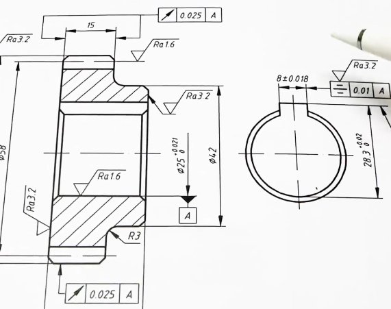
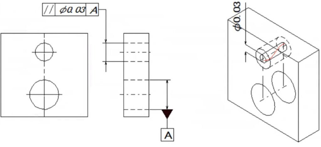
Geometric Dimensioning and Tolerancing (GD&T)
Geometric Dimensioning and Tolerancing, commonly known as GD&T, is a symbolic system used to define allowable variations in geometry rather than just size.
GD&T specifies tolerances for features such as:
- Flatness
- Parallelism
- Perpendicularity
- Concentricity
- Position
- Runout
This system is especially important for complex assemblies where the relationship between multiple surfaces affects product performance.
GD&T helps eliminate ambiguity in engineering drawings and allows manufacturers to better understand functional design requirements.
ASME Y14.5 Standard
Another widely used tolerance standard is ASME Y14.5, which defines dimensioning and tolerancing practices primarily used in North America.
ASME Y14.5 includes detailed guidelines for:
- Dimensioning rules
- Tolerance interpretation
- GD&T symbols and definitions
- Feature control frames
Many aerospace and defense industries rely on ASME standards to maintain strict engineering documentation and quality control.
Types of Machining Tolerances
CNC machining tolerances can be classified into several types depending on the dimensional control required.
Linear Tolerances
Linear tolerances define acceptable variation in length, width, height, or diameter. These are the most common tolerances used in machining drawings.
For example:
25 mm ±0.1 mm
This indicates the dimension may vary between 24.9 mm and 25.1 mm.
Bilateral Tolerances
Bilateral tolerances allow variation in both directions from the nominal dimension.
Example:
50 mm ±0.05 mm
This type of tolerance is commonly used in mechanical engineering.
Unilateral Tolerances
Unilateral tolerances allow variation only in one direction.
Example:
20 mm +0.00 / −0.05 mm
This ensures the dimension never exceeds the maximum limit but allows slight reduction if necessary.
Limit Tolerances
Limit tolerances define the maximum and minimum acceptable dimensions directly.
Example:
30.00 mm / 29.95 mm
Manufacturers must ensure the final part falls within these limits.
Factors That Affect CNC Machining Tolerance
Several technical factors influence the achievable tolerance during CNC machining.
Machine Accuracy
High-quality CNC machines with advanced control systems can achieve tighter tolerances. Machine rigidity and positioning accuracy significantly affect dimensional precision.
Tool Condition
Cutting tools wear over time, which can reduce machining accuracy. Tool wear may cause dimensional drift, especially during long production runs.
Material Properties
Different materials respond differently to machining processes. Softer materials like aluminum may deform slightly during machining, while harder materials like stainless steel generate more heat and tool wear.
Thermal Expansion
Heat generated during cutting can cause both the workpiece and the cutting tool to expand. Thermal effects can influence dimensional accuracy if not properly controlled.
Part Geometry
Complex geometries, thin walls, or deep cavities are more difficult to machine accurately. Flexible structures may vibrate during cutting, leading to dimensional deviations.
Fixturing and Workholding
Stable workholding is essential for maintaining precision. Poor fixturing can allow movement during machining, which directly affects tolerance control.
CNC Machining Tolerance vs Manufacturing Cost
One of the most important relationships in manufacturing is the trade-off between tolerance and cost. Generally, tighter tolerances lead to higher production costs.
Reasons include:
- Additional machining operations
- Slower cutting speeds
- Specialized cutting tools
- Increased inspection procedures
- Higher scrap rates
For example, reducing tolerance from ±0.1 mm to ±0.01 mm may increase machining costs significantly because it requires much more precise process control.
Therefore, engineers should always evaluate whether tight tolerances are truly necessary for the component's function.
How to Choose the Right Tolerance
Selecting appropriate machining tolerances requires careful consideration of product design and manufacturing capability.
Identify Functional Requirements
Critical features such as bearing fits, sealing surfaces, and alignment components often require tight tolerances.
Apply Standard Tolerances
Non-critical features should follow standard tolerance ranges such as ISO 2768. This simplifies manufacturing and reduces cost.
Consult Manufacturing Engineers
Early collaboration with CNC machining specialists helps identify potential manufacturing challenges and optimize tolerance selection.
Consider Assembly Requirements
Tolerances should ensure that mating components fit correctly without excessive force or looseness.
Design Tips to Improve CNC Machining Efficiency
Designing parts with manufacturability in mind can significantly improve production efficiency.
Key recommendations include:
Avoid unnecessary tight tolerances
Only specify tight tolerances where functionally required.
Use standard drill and tool sizes
Custom tool sizes increase machining complexity.
Minimize deep cavities
Deep pockets require longer tools that may reduce machining stability.
Maintain consistent wall thickness
Thin walls are more prone to vibration and deformation during machining.
Allow adequate corner radii
Sharp internal corners are difficult to machine because tools are round.
These design considerations help improve machining accuracy while reducing production cost.
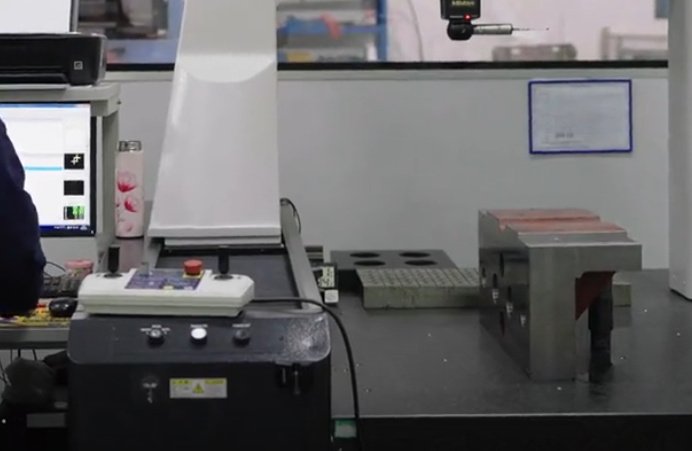
Quality Control and Inspection
Maintaining tolerance accuracy requires proper inspection methods throughout the manufacturing process.
Common inspection tools include:
- Coordinate Measuring Machines (CMM)
- Digital calipers and micrometers
- Optical measurement systems
- Surface roughness testers
Advanced quality control systems ensure parts meet tolerance requirements before shipment.
Statistical process control (SPC) is also widely used in high-volume manufacturing to monitor dimensional variation and maintain consistent production quality.
Conclusion
CNC machining tolerance standards play a crucial role in ensuring dimensional accuracy, product functionality, and manufacturing efficiency. By understanding tolerance classifications, international standards such as ISO 2768 and GD&T, and the factors that influence machining precision, engineers can design parts that balance performance and cost.
Proper tolerance selection not only ensures reliable assembly but also improves production efficiency and reduces manufacturing expenses. When designing CNC machined components, the best approach is to apply tight tolerances only where necessary while relying on standard tolerance ranges for non-critical features.
As manufacturing technology continues to evolve, CNC machining will remain one of the most reliable and versatile processes for producing high-precision components across a wide range of industries.
