
Wire electrical discharge machining (Wire EDM or WEDM) is a non-contact, thermal material removal process used to cut conductive materials with exceptional precision. A thin, continuously fed wire electrode cuts intricate profiles by generating a series of controlled electrical discharges in a dielectric fluid. This guide explains the fundamentals, equipment, process parameters, applications, and practical considerations required to use Wire EDM effectively in precision manufacturing.
Fundamentals of Wire EDM Machining
Wire EDM is a type of electrical discharge machining where material is removed by rapidly recurring electrical sparks between a wire electrode and the workpiece. Both the electrode and the workpiece must be electrically conductive. The process does not rely on cutting forces; instead, it uses controlled spark erosion to shape the material.
Basic Working Principle
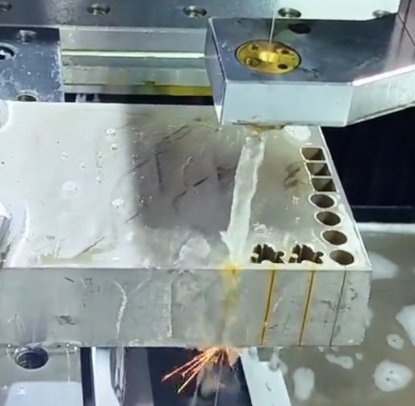
The machine feeds a thin wire electrode, typically brass or coated brass, along a programmed path. The wire and workpiece are immersed in or flushed with dielectric fluid, usually deionized water. A power supply applies pulsed voltage between wire and workpiece, producing a series of sparks across a small gap. Each spark melts and vaporizes a tiny volume of material, which is then flushed away by the dielectric. The CNC system coordinates motion of the upper and lower wire guides to produce the desired geometry.
Key Characteristics of the Process
- Non-contact cutting: no mechanical cutting forces on the workpiece
- Capability to cut very hard or tough materials without tool wear issues typical of conventional machining
- High aspect ratio cuts and narrow kerf widths
- Excellent dimensional accuracy and repeatability
- Ability to produce complex 2D and tapered 3D profiles
Wire EDM removes material only where electrical discharges occur, so it is highly controllable. However, because it is a thermal process, the resulting surface may have a recast layer and heat-affected zone, which must be considered in critical applications.
Wire EDM Machine Components and Configuration
Understanding the main components of a Wire EDM machine helps in setup, parameter selection, and troubleshooting. Machines are built around a rigid structure with precise motion control systems and specialized subsystems for electricity, wire feeding, and dielectric management.
Mechanical Structure and Axes
Most Wire EDM machines have a rigid base with precision linear guides and ball screws (or linear motors) driving the X and Y axes. The workpiece is fixed on the table, and the wire is guided above and below the work zone. Many machines include U and V axes to move the upper head relative to the lower head, enabling taper cuts and 3D geometries. Z-axis motion adjusts the vertical position of the wire guides relative to the workpiece thickness.
Wire Feeding and Guiding System
The wire system includes the wire spool, tensioning devices, drive rollers, guides, and a wire collection mechanism. The wire is continuously fed from a supply spool, through upper and lower guides, and then into a disposal container or chopper. Constant wire tension is crucial for accuracy and to maintain a straight cutting path. Guides are usually made of hard materials such as diamond or sapphire to minimize wear and maintain alignment.
Dielectric Supply and Filtration
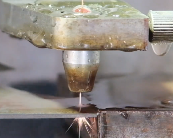
The dielectric system pumps deionized water into the cutting zone through nozzles close to the wire. The fluid cools the workpiece and wire, flushes away eroded particles, and acts as an electrical insulator until breakdown voltage is reached. The system controls water resistivity (conductivity) through ion exchange resins, and uses filters to remove debris. Proper dielectric condition is essential to stable spark generation, good surface finish, and reliable dimensional accuracy.
Power Supply and Control Unit
The power supply generates controlled voltage pulses with defined on-time, off-time, current, and peak power. Modern machines use digital generators to adjust parameters dynamically along the toolpath. The CNC controller coordinates axis motion, wire feed, automatic threading, and adaptive control functions such as anti-electrolysis or corner control. Machine interfaces typically allow operators to select machining modes based on material, thickness, and required finish.
Wire EDM Process Steps
The Wire EDM workflow consists of part design and programming, machine setup, threading and alignment, rough cutting, and optional trim passes. Each step influences productivity and final part quality.
Design and Programming
Wire EDM usually starts from a 2D profile or a 3D model defining the upper and lower contours. CAM software or the machine’s onboard programming system is used to generate toolpaths, offsets, and cutting conditions. In many cases, the programmer defines separate passes for roughing and finishing with different parameter sets. Part features like small radii, fine slots, and tight corners require careful control of corner compensation and wire lag.
Workpiece Preparation and Fixturing
The workpiece must be securely clamped or mounted to prevent movement during cutting and flushing. Clamping methods include vises, magnetic chucks (for ferrous materials), threaded fixtures, or custom plates. The fixturing should provide sufficient support while leaving clearance for the wire to enter and exit the cut path. For through-cuts, a start hole is often drilled using EDM drilling or conventional drilling, especially when cutting from inside a closed profile.
Wire Threading and Alignment
Automatic wire threading systems feed the wire through the upper and lower guides and through the start hole. Modern machines can rethread automatically at the break point if the wire breaks during cutting. Correct alignment of the wire relative to the workpiece datum is established using probing routines, edge-finding, or reference marks. Accurate alignment is essential when cutting multiple features or when using multiple setups.
Rough Cutting and Trim Passes
Typically, the first pass is a rough cut with higher energy discharges for maximum material removal. This leaves a slightly oversize profile with a relatively rough surface. After roughing, multiple trim passes with lower discharge energy refine the contour, reduce wire offset, and improve surface finish. The number of finishing passes depends on required tolerance and surface quality. Some parts may require only one or two passes, while high-precision components may need several trim cuts.
Materials Suitable for Wire EDM
Wire EDM is limited to electrically conductive materials but has a broad material range within that constraint. It is especially effective for hard-to-machine materials and heat-treated components.
Common Workpiece Materials
- Tool steels (e.g., A2, D2, H13) in hardened condition
- Carbide and cermets
- Stainless steels (austenitic, martensitic, precipitation hardening grades)
- Titanium alloys
- Nickel-based superalloys (Inconel, Hastelloy)
- Aluminum and copper alloys
- Graphite (when embedded or backed by conductive fixtures)
Wire EDM is often applied after heat treatment so that the final geometry is produced without introducing mechanical distortion. Because the process is independent of material hardness, cutting speed depends more on electrical and thermal properties than on hardness or strength.
Material Properties Influencing Performance
Material electrical conductivity affects discharge behavior and attainable cutting speeds. Thermal conductivity and melting temperature influence the size of craters and the degree of recast layer. Some high conductivity materials may require specific parameter sets to maintain stable discharge, while very low conductivity alloys may demand tight control of dielectric resistivity. Material microstructure also affects surface integrity and the appearance of the etched surface.
Wire Types, Diameters, and Coatings
The choice of wire electrode significantly affects process stability, cutting speed, and achievable accuracy. Wire composition, diameter, and coating determine mechanical strength, electrical and thermal behavior, and resistance to wear.
Wire Materials and Coatings
Standard wire is usually brass with a copper-zinc composition, offering good conductivity and reasonable strength. Diffusion-annealed and coated wires, such as zinc-coated or gamma-phase brass wires, are used to improve performance at higher cutting speeds or in challenging materials. Molybdenum wire may be used in some systems, especially in machines designed for reusable wire in specific applications, though continuous-feed brass wire is more common in production environments.
Wire Diameter Selection
Typical wire diameters range from about 0.05 mm to 0.30 mm. Smaller diameters enable finer kerf width and smaller internal corners but reduce cutting speed and may require more careful tension control. Larger wires provide higher cutting rates and improved stability in thick or tall parts. The selection depends on the required minimum corner radius, slot width, material thickness, and tolerance requirements.
| Wire Diameter (mm) | Typical Kerf Width (mm) | Typical Application Range | Relative Cutting Speed |
|---|---|---|---|
| 0.10 | ≈ 0.13–0.15 | Micro-features, fine slots, small radii | Low |
| 0.20 | ≈ 0.23–0.25 | General-purpose precision cutting | Medium |
| 0.25 | ≈ 0.28–0.30 | Thicker sections, higher productivity | High |
Electrical Parameters and Their Effects
Electrical discharge parameters are central to controlling cutting speed, surface finish, and accuracy. On modern machines, many settings are grouped into technology tables, but understanding their roles supports better process optimization.
Pulse On-Time and Off-Time
Pulse on-time determines how long current flows during each discharge. Longer on-time usually increases material removal per spark and thus cutting speed, but also enlarges crater size, roughens the surface, and can increase the recast layer thickness. Off-time is the interval between pulses, allowing debris to be removed and the dielectric to recover its insulating properties. Too short an off-time may cause unstable discharges, short circuits, or wire breakage; too long an off-time reduces productivity.
Peak Current and Spark Energy
Peak current, together with on-time, defines the energy of each spark. Higher peak current increases removal rate but can worsen surface finish and increase thermal impact on the workpiece. For finishing cuts, lower peak current settings are used to limit crater size and improve surface roughness. Stable and repeatable current control is necessary to maintain consistent results across a part or a batch of parts.
Open-Circuit Voltage and Gap Control
Open-circuit voltage influences the spark gap and ionization behavior. Higher voltage can support a larger gap, improving flushing and debris removal, but may reduce accuracy if not properly controlled. The control system constantly monitors gap conditions and adjusts feed rate, voltage, or other parameters to maintain a consistent discharge gap. This automatic gap control is essential for avoiding short circuits and wire breaks.
Wire Tension and Feed Rate
Wire tension helps maintain a straight electrode path, especially over long vertical heights. Low tension may allow wire vibration and deflection; excessively high tension increases the risk of mechanical breakage. Feed rate is controlled automatically by the CNC based on spark feedback, but operators can define maximum feed limits. In corners or small details, the machine automatically reduces feed to limit wire lag and maintain dimensional accuracy.
Tolerances and Surface Finishes Achievable
Wire EDM is widely used where tight tolerances and superior surface quality are required. The achievable precision depends on machine capability, setup quality, material, and the number of trim passes applied.
Dimensional Accuracy and Repeatability
Modern precision Wire EDM machines can achieve dimensional tolerances on the order of ±2–3 μm under controlled conditions for small parts and short heights. For typical industrial applications, tolerances of ±5–10 μm are common, especially when appropriate finishing passes are used. Repeatability is often within a few micrometers, making the process suitable for series production of high-precision components.
Surface Roughness Ranges
Surface finish is expressed in terms of Ra or other roughness parameters. Roughing passes may leave Ra values around 2–3 μm or higher, while fine finishing passes can achieve Ra near or below 0.2 μm, depending on material and machine technology. Multiple low-energy trim cuts reduce the recast layer and refine the surface microtopography, improving both appearance and functional performance in contact surfaces or sealing interfaces.
Kerf Width and Corner Radius
The kerf width is slightly larger than the wire diameter due to the spark gap. This must be considered when programming offsets and calculating final feature dimensions. Internal corner radius is inherently limited by the wire radius and the spark gap; for sharp internal corners, the effective radius will always be at least the kerf radius. Designers often integrate small reliefs or clearance pockets when sharp corners are required for mating parts.
Geometric Capabilities and Part Features
Wire EDM is particularly well suited for geometries that are challenging for conventional machining, especially when high precision and intricate profiles are required. It is commonly used for tool and die components, medical devices, fine mechanical parts, and precision inserts.
2D Profiles and Contours
The process excels at cutting complex 2D profiles in plates or blocks. Examples include punch and die outlines, gears, cams, spline profiles, and intricate contours in mold inserts. Because cutting forces are negligible, slender features and small webs can be produced without risk of bending or vibration. Parts may be stacked and cut in groups, provided the stack is clamped rigidly and flushing is adequate.
Taper Cutting and 3D Forms
With independent U and V axis motion, Wire EDM can produce tapers and variable cross-sections by offsetting the upper guide relative to the lower guide. This enables tapered die sections, relief angles, and certain 3D shapes defined by different upper and lower profiles. The maximum taper angle depends on machine design, workpiece thickness, and nozzle configuration. Programming must account for wire lag and geometry compensation when producing steep tapers or complex 3D transitions.
Micro Features and Fine Details
Using fine wires and optimized parameters, Wire EDM can create micro-scale features such as narrow slots, fine teeth, and precision micro-geometries in hard materials. Limitations include the minimum reliable wire diameter, machine resolution, and the ability to maintain stable discharge conditions in very small gaps. Debris removal and dielectric quality become more critical as feature size decreases.

Setup, Fixturing, and Workholding Practices
Proper setup and fixturing are essential to harness the precision of Wire EDM. Inadequate workholding or poor alignment can quickly degrade tolerances and surface quality.
Fixturing Strategies
Workholding must prevent any movement during cutting and flushing. Fixtures should provide sufficient rigidity while minimizing obstruction of the wire path and flushing nozzles. Common approaches include base plates with locating pins, modular fixturing systems, and dedicated jigs for recurring parts. For high-accuracy work, fixturing must also address thermal stability and maintain consistent reference datums across multiple operations.
Thermal Considerations in Setup
Wire EDM involves localized thermal input, but overall cutting forces are low. Nonetheless, temperature variation in the machine or workshop can cause small dimensional shifts. Some machines operate with temperature-controlled dielectric fluid and stable ambient conditions to reduce thermal drift. For tight tolerance applications, it is useful to allow machine and workpiece to reach thermal equilibrium before final finishing passes.
Reference Systems and Datum Control
Accurate parts require a well-defined datum system. The initial setup usually establishes a primary datum from a machined surface, edge, or reference pin. Subsequent operations or remounting procedures use probing or mechanical stops to relocate parts within micrometer-level repeatability. Reliable datum control is especially important when integrating Wire EDM into multi-stage manufacturing routes with milling, turning, or grinding.
Flushing, Debris Removal, and Stability
Effective flushing of eroded particles from the spark gap is critical to process stability, surface finish, and wire life. Poor flushing often manifests as unstable arcing, short circuits, or wire breakage.
Nozzle Positioning and Flushing Pressure
The dielectric nozzles should be positioned as close as practical to the workpiece surfaces while avoiding interference with the part or fixture. Flushing pressure must be high enough to remove debris but not so high as to deflect the wire or move small parts. For intricate geometries or closed cavities, auxiliary flushing through drilled holes or scrap relief cuts can improve debris evacuation.
Dielectric Quality and Filtration
The dielectric fluid must maintain suitable resistivity to support consistent spark initiation and avoid unwanted electrochemical effects. Filters remove particulate matter; clogged filters or high debris load increase short circuit frequency and reduce cutting stability. Monitoring and maintaining filter condition, tank cleanliness, and resin performance are routine tasks in Wire EDM operations.
Indicators of Flushing-Related Issues
Common symptoms of inadequate flushing include excessive wire breaks, unstable cutting speed, poor surface finish, and localized overburning. Adjustments may involve modifying nozzle distance, flushing pressure, machining parameters, or adding auxiliary flushing paths. In thicker workpieces, careful planning of cut sequences and start holes can improve flushing effectiveness.
Automation, Multi-Pass Cutting, and Process Planning
Wire EDM integrates well with automation and unattended operation due to its predictable electrical control and low tool wear. Process planning focuses on balancing speed, accuracy, and surface quality through appropriate pass strategies and sequencing.
Roughing and Finishing Strategies
The most common strategy is to use one rough cut followed by one or more trim cuts. Roughing uses higher energy settings and a larger offset to prioritize material removal and stability. Finishing passes progressively reduce offset and discharge energy to reach the final dimension and surface specification. For very high precision work, subsequent trim passes may employ different flushing conditions and reduced wire speed to minimize variability.
Cut Sequencing and Part Separation
Careful planning of cut order reduces the risk of part movement and maintains structural rigidity during machining. Often, skeleton structures or tabs are left to hold parts in place until the last operations. When cutting multiple components from a single plate, the sequence is chosen to maintain connectivity and avoid collapse of narrow webs. After the final cuts, parts are removed and deburred as needed, typically with minimal effort due to the clean nature of EDM edges.
Unattended and Lights-Out Operation
Many shops run Wire EDM machines unattended during nights or weekends. Reliable unattended operation depends on stable threading, sufficient wire and filter capacity, robust fixturing, and conservative parameter selection to reduce wire break risk. Machines may include automatic wire rethreading, automatic tank level control, and monitoring functions that pause operation in case of anomalies.
Quality Control, Inspection, and Surface Integrity
Because Wire EDM is often used for critical components, systematic quality control and inspection are essential. Dimensional verification, surface integrity assessment, and documentation ensure that produced parts meet functional requirements.
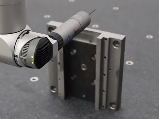
Dimensional Inspection Methods
Dimensional checks are usually performed using coordinate measuring machines, optical comparators, or precision gauge blocks and pins. For small features or micro components, high-magnification optical or vision systems are common. CNC programs and process logs may be tied to inspection records to trace parameter sets used for specific batches.
Surface and Subsurface Considerations
Wire EDM surfaces consist of overlapping craters from individual sparks. Beneath the surface, a thin recast layer may exist, along with a heat-affected zone whose thickness depends on discharge energy and trim pass sequence. In many applications, the recast layer is acceptable; in others, it may be minimized by low-energy finishing passes or removed by subsequent polishing, lapping, or light grinding, depending on functional and regulatory requirements.
Managing Process Consistency
| Factor | Influence on Process | Typical Control Measures |
|---|---|---|
| Dielectric condition | Spark stability, surface finish, dimensional consistency | Regular filter changes, conductivity monitoring, tank cleaning |
| Wire quality | Wire breaks, kerf uniformity, corner accuracy | Using specified wire grade, proper storage, controlled tension |
| Machine calibration | Axis accuracy, taper control, repeatability | Periodic calibration, backlash checks, alignment verification |
| Fixturing stability | Part movement, dimension shift, surface defects | Rigid clamping, proper support, thermal management |
Common Practical Considerations in Wire EDM
Deploying Wire EDM efficiently requires attention to several practical aspects of planning and operation. These considerations influence overall throughput, per-part cost, and reliability.
Machining Time and Productivity Factors
Machining time depends on material type, thickness, wire diameter, and chosen electrical parameters. Rough cuts are often the main contributor to cycle time, especially in thick materials. Trim passes add time but are essential for tight tolerances and fine finishes. Productivity can be improved through stacking multiple parts, optimizing cut paths to minimize idle travel, and using high-performance wire and technology settings appropriate for the material.
Wire Consumption and Operating Cost
Wire is continuously consumed and represents a significant operating cost. Thicker wires and higher speeds increase consumption; fine wires reduce kerf but can increase total cycle time. Dielectric fluid, filters, ion exchange resins, and maintenance also contribute to cost. A systematic approach to parameter selection, preventive maintenance, and job planning helps maintain a favorable balance between precision and cost.
Typical Pain Points in Wire EDM Use
Common difficulties include wire breakage in thick or poorly flushed cuts, unexpected dimensional shifts due to insufficient fixturing rigidity, and extended cycle times for parts requiring multiple fine finishing passes. Addressing these issues often involves revising cut sequences, adjusting flushing conditions, selecting more suitable wire types, or revisiting fixture design.
Applications of Wire EDM in Industry
Wire EDM is widely used across industries where precision and the ability to cut hard materials are essential. Its non-contact nature and predictable accuracy make it a central process in toolrooms and precision manufacturing environments.
Tool and Die Manufacturing
In tool and die work, Wire EDM is used to produce punches, dies, inserts, and core pins with tight clearance relationships. It allows accurate production of mating components with minimal fitting. Fine clearance and relief geometries in stamping dies and complex slide forms in molds are routinely produced with Wire EDM, often after heat treatment to preserve final geometry.
Aerospace, Medical, and Precision Engineering
In aerospace and power generation, Wire EDM processes turbine components, cooling slots, and difficult alloys. In medical device manufacturing, it is used for components made from stainless steels, titanium, and cobalt-based alloys, where precision and surface condition are crucial. Precision engineering and instrumentation benefit from the ability to create fine mechanisms, micro-structures, and complex profiles with reliable repeatability.
Production of Prototyping and One-Off Parts
Because Wire EDM requires no dedicated cutting tools and minimal setup changes for different profiles, it is suitable for prototypes and low-volume, high-precision parts. Complex shapes can be produced directly from CAD data without the need for specialized cutting tools, enabling flexible and accurate production in development environments.
Safety and Environmental Considerations
Wire EDM operates with high voltage, dielectric fluids, and moving mechanical components. Appropriate safety measures and environmental practices are necessary for reliable operation and regulatory compliance.
Electrical and Mechanical Safety
The machine enclosure protects operators from direct contact with high voltage and moving axes. Interlocks typically prevent machine operation with doors open. Operators should follow manufacturer guidelines for grounding, cable handling, and maintenance procedures. Mechanical hazards, such as moving tables and rotating wire spools, require basic machine guarding and standard industrial safety practices.
Handling of Dielectric Fluids and Waste
Dielectric water is generally non-hazardous, but sludge containing metallic particles must be collected and disposed of in accordance with local environmental regulations. Filter cartridges, spent resins, and wire scrap must be handled as industrial waste. Proper handling reduces contamination risks and ensures clean, stable operation.
Workplace Environment and Ergonomics
Maintaining a clean environment around the machine, including managing splashes and humidity from the tank, supports both quality and equipment longevity. Ergonomic considerations include accessible worktables, easy loading of heavy workpieces, and safe handling of large wire spools. Good lighting and clear viewing windows assist in setup, inspection, and ongoing monitoring.
FAQ
What is Wire EDM machining?
Wire EDM machining is a precision manufacturing process that uses a thin electrically charged wire to cut conductive materials without direct mechanical contact.
How does Wire EDM achieve high precision?
Wire EDM uses computer numerical control (CNC) and electrical discharges instead of cutting force, allowing extremely tight tolerances and intricate shapes.
What are the advantages of Wire EDM over traditional machining?
Advantages include high accuracy, minimal material stress, ability to cut complex geometries, and excellent surface finishes.
What factors affect Wire EDM machining cost?
Cost depends on material type, thickness, part complexity, tolerance requirements, machining time, and production volume.
