
CNC machinery is the backbone of modern precision manufacturing. It combines computer control with high‑performance machine tools to produce complex parts with high repeatability, tight tolerances, and efficient throughput. This guide explains CNC machinery from the ground up, focusing on practical, technical, and system-level details for industrial and engineering users.
What CNC Machinery Is and How It Works
CNC (Computer Numerical Control) machinery refers to machine tools driven by programmed commands encoded in a numerical format. Instead of manual handwheels, levers, or templates, axes and functions are controlled by servo or stepper motors under the direction of a CNC controller.
The working principle can be summarized as:
- Generate toolpaths (CAM or manual programming)
- Convert toolpaths into CNC code (e.g., G-code)
- Send code to the controller
- Controller interpolates positions and velocities
- Drives motors and actuators to remove material or shape the workpiece
Key characteristics include numerical positioning in multiple axes, automatic tool changes (on many machines), programmable spindle speed and feed, and integrated sensing and feedback (encoders, probes, load monitoring).

Major Types of CNC Machinery
CNC machinery spans a wide range of machine tools. Understanding the main categories helps in selecting appropriate equipment for specific manufacturing tasks.
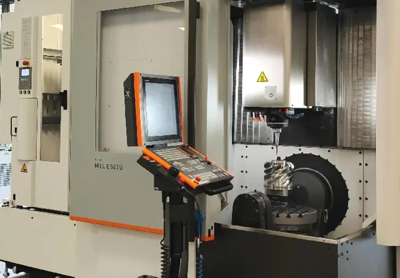
CNC Milling Machines
CNC milling machines remove material using a rotating cutting tool while the workpiece is clamped on a table. They are suited for prismatic parts, cavities, planes, and 3D surfaces.
Common configurations:
- 3-axis mills: X, Y, Z
- 4-axis mills: X, Y, Z plus rotary axis (A or B) for indexing or contouring
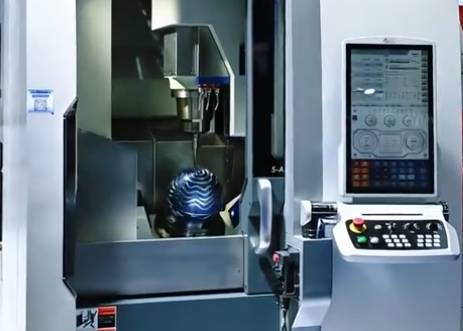
- 5-axis mills: X, Y, Z plus two rotary axes, enabling tool orientation control
Vertical machining centers (VMC) have a vertical spindle orientation, while horizontal machining centers (HMC) have a horizontal spindle with pallets and better chip evacuation.
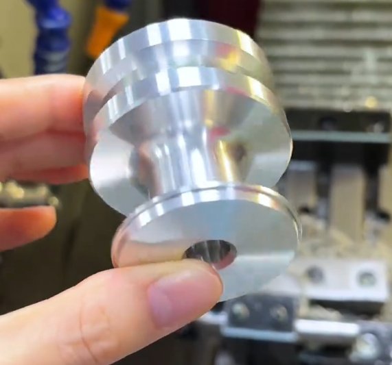
CNC Turning Centers and Lathes
CNC turning machinery rotates the workpiece about a spindle axis while stationary tools cut external and internal features. It is ideal for shafts, bushings, discs, and other rotationally symmetric components.
Variants include:
• 2-axis lathes: X (radial) and Z (axial) axes for OD/ID turning, facing, grooving.
• Turn-mill centers: Add C-axis spindle control and live tooling (driven tools) to perform milling, drilling, and tapping on the lathe.
• Multi-turret and multi-spindle machines: Increase productivity for mass production by parallelizing operations.
CNC Machining Centers
Machining centers are CNC mills equipped with automatic tool changers (ATCs) and often advanced features such as pallet changers, tool life management, and high-speed spindles. They are used for complex parts that require many tools and operations in one setup.
CNC Grinding Machines
CNC grinders use abrasive wheels to achieve high surface quality and very tight tolerances. Examples are surface grinders, cylindrical grinders, and centerless grinders with CNC controls on wheel positioning, infeed, and dressing cycles.
CNC EDM and Wire EDM
CNC electrical discharge machining (EDM) removes material by spark erosion between an electrode and the workpiece. Die-sinking EDM uses a shaped electrode, while wire EDM uses a continuously fed wire. These machines are used for hard materials, sharp internal corners, and intricate cavities.
CNC Routers and Woodworking Machines
CNC routers are used for woodworking, plastics, composites, and soft metals. They often have large working envelopes, vacuum tables, and high-speed spindles optimized for routing rather than heavy metal removal.
CNC Laser, Plasma, and Waterjet Machines
These CNC machines are primarily used for cutting flat sheet material. Control of motion and power (laser), current (plasma), or pressure (waterjet) enables precise cutting without mechanical cutting tools.
CNC Swiss-Type and Multi-Spindle Machines
Swiss-type CNC lathes support the workpiece with a guide bushing close to the cutting zone, enabling high-precision machining of slender parts. Multi-spindle CNC machines use multiple spindles to machine several parts or several operations simultaneously, increasing throughput.
Key Components and Subsystems of CNC Machinery
The performance and reliability of a CNC machine depend on its mechanical, electrical, and control subsystems. Understanding these subsystems is essential for selection, operation, and troubleshooting.
Machine Structure and Axis Assemblies
The base, column, saddle, and table form the structural backbone. Materials are usually cast iron, steel weldments, or mineral castings. Key parameters include stiffness, damping characteristics, and thermal behavior.
Axes are typically guided by linear guides (roller or ball type) or box ways. Motion is generated via ball screws, rack-and-pinion systems, or linear motors. Positional feedback comes from rotary or linear encoders.
Spindle System
The spindle holds and rotates the cutting tool or workpiece. Critical specifications:
- Maximum speed (rpm)
- Power (kW or hp) and torque curve
- Bearing type (angular contact, hybrid ceramic, hydrostatic)
- Taper interface (e.g., BT40, CAT40, HSK63A, Morse taper)
High-speed spindles may use direct-drive motors, while heavy-duty spindles can be belt-driven or gear-driven.
Control, Drives, and Feedback
The CNC control unit interprets the program, performs interpolation, and generates motion commands. Servo drives convert these commands into electrical power for servo motors on each axis.
Feedback systems close the control loop. Common sensors include:
• Rotary encoders on motor shafts
• Linear scales on axes for higher positioning accuracy
• Spindle encoders for rigid tapping and spindle orientation
Tooling, Tool Holders, and ATC
Cutting tools are mounted in standardized holders or collets. The automatic tool changer stores tools in a magazine or carousel and exchanges them under CNC control.
Key parameters:
• Tool capacity (number of tool stations)
• Maximum tool length, weight, and diameter
• Tool change time (chip-to-chip time)
Workholding Systems
Workholding provides secure and accurate clamping. Options include vises, chucks, collets, pallets, modular fixturing, and vacuum tables. Precision and repeatability of workholding directly affect part accuracy and changeover time.
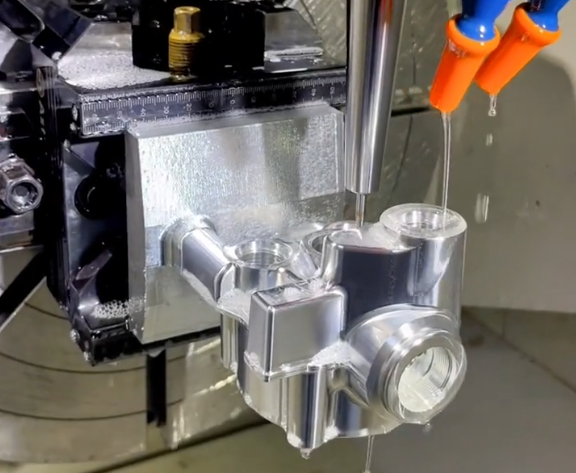
Coolant, Lubrication, and Chip Management
Coolant systems deliver cutting fluids for cooling and lubrication and for chip evacuation. Centralized lubrication systems supply oil or grease to ball screws and guideways at controlled intervals. Chip conveyors and filters manage swarf and maintain a clean cutting environment.
Probing and Measurement
Touch probes and laser measurement systems automate workpiece setup, tool length and diameter measurement, and in-process inspection. They feed measurement data back to the CNC control to adjust offsets or stop the process if deviations occur.
CNC Control Systems and Programming
The CNC control system executes motion commands, manages machine functions, and provides the human–machine interface (HMI). Programming is typically done using G-code, often generated by CAM software.
G-Code and M-Code Fundamentals
G-code defines motion and machining cycles, while M-code controls machine functions such as spindle on/off and coolant. Common examples:
• G00: rapid positioning
• G01: linear interpolation (cutting feed)
• G02/G03: circular interpolation (CW/CCW)
• G17/G18/G19: plane selection
• G40/G41/G42: cutter radius compensation off/left/right
• G54–G59: work coordinate systems
• M03/M04/M05: spindle clockwise/counterclockwise/stop
• M08/M09: coolant on/off
Coordinate Systems and Positioning
CNC machines use machine coordinates and work coordinate systems (WCS) to define positions. Operators set work offsets (e.g., G54) based on datums on the workpiece or fixture.
Absolute programming (G90) specifies coordinates relative to the origin, while incremental programming (G91) specifies movements relative to the current position.
Canned Cycles and Advanced Functions
Canned cycles simplify repetitive operations such as drilling, tapping, or boring. Examples include drilling (G81), peck drilling (G83), and tapping cycles (G84). Advanced cycles manage roughing, finishing, and tool-path optimization.
Advanced CNC controls offer macro programming, custom variables, and parametric logic for flexible programs, family-of-parts machining, and adaptive sequences.
Manual Programming vs. CAM-Generated Code
Manual programming is used for simple parts, setup operations, or quick one-off tasks. CAM systems generate code for complex 3D surfaces, multi-axis machining, and optimized toolpaths. CAM workflows typically include model import, feature recognition, tool selection, operation definition, simulation, and post-processing to specific CNC control dialects.
Capabilities, Performance Metrics, and Specifications
CNC machinery performance is defined by its motion range, speed, precision, spindle characteristics, and tooling capacity. Key metrics are usually listed in the machine specification sheet.
| Parameter | Typical Range | Notes |
|---|---|---|
| X-axis travel | 400–2,000 mm | Depending on machine size |
| Y-axis travel | 300–1,000 mm | Vertical machining centers |
| Z-axis travel | 300–1,000 mm | Spindle nose to table |
| Rapid traverse rate | 20–60 m/min | Higher on linear motor machines |
| Max cutting feed | 10–30 m/min | Material and tooling dependent |
| Spindle speed | 6,000–24,000 rpm | High-speed models may exceed 40,000 rpm |
| Spindle power | 7–50 kW | Continuous rating |
| Positioning accuracy | ±0.002–±0.010 mm | According to machine and calibration |
| Repeatability | ±0.001–±0.005 mm | Key for consistent production |
| Tool magazine capacity | 20–240 tools | Chain or drum type magazine |
| Table load capacity | 200–3,000 kg | Varies with machine size |
Actual values depend on the exact machine model, size, and design. For turning centers, equivalent specifications include maximum swing, turning length, spindle bore, turret stations, and bar capacity.
Materials and Applications for CNC Machinery
CNC machinery operates across metals, plastics, composites, and other engineered materials. Material properties influence tool selection, cutting parameters, and achievable tolerances.
Metals
CNC machines commonly process steel, stainless steel, aluminum, copper, brass, titanium, and superalloys. Cutting data is adjusted according to hardness, thermal conductivity, and chip formation characteristics. Hardened steels and nickel-based alloys demand more rigid machines, optimized coolant, and advanced tooling.
Non-Metallic Materials
Plastics and polymers (such as POM, PEEK, PTFE), composites (such as CFRP, GFRP), and wood-based materials are frequently machined on CNC routers and mills. Tool geometry, chip evacuation, and heat management require specific attention to avoid melting, delamination, or surface damage.
Industry Sectors
CNC machinery is used extensively in:
• Automotive and transportation components
• Aerospace structures and engines
• Medical devices and implants
• Energy and power generation equipment
• Mold, die, and tooling manufacturing
• Electronics and precision instrumentation
Process Planning and Workholding Considerations
Effective use of CNC machinery depends on systematic process planning: operation sequencing, fixturing, and tool selection.
Operation Sequencing
Typical routing includes roughing, semi-finishing, and finishing operations. Sequence planning considers stability (removing material while maintaining rigidity), datum strategy, and minimizing repositioning. For multi-axis machines, operations are consolidated to reduce set-ups.
Fixturing and Datums
Fixturing must provide rigidity, accurate location, and accessibility for tools and inspection. Locating surfaces are chosen as functional datums for the part. Modular fixtures, zero-point clamping systems, and pallets increase repeatability and reduce changeover time.
Tool Selection and Tool Management
Cutting tools are chosen based on material, geometry, and required surface finish. Parameters include coating, substrate, flute count, helix angle, and radius. Tool management encompasses identification (e.g., RFID tags), storage, presetting, and life monitoring to prevent unexpected tool failure and maintain consistent quality.
Accuracy, Precision, and Quality Control
Accuracy and repeatability are central to CNC machining performance. Errors arise from mechanical tolerances, backlash, thermal expansion, tool wear, and workholding deformation.
Geometric Accuracy
Geometric accuracy includes straightness, squareness, backlash, and positioning error along each axis. Machines are characterized using test standards such as ISO or similar, and compensation tables can correct positional deviations at the control level.
Thermal Effects
Heat from spindles, drives, and the environment causes thermal growth. Strategies to manage this include symmetrical machine structures, spindle cooling, ballscrew cooling, and real-time offset compensation based on temperature sensors or probing.
Measurement and Inspection
Dimensional verification can be done in-process using machine probes, or offline using coordinate measuring machines (CMMs), gauges, and surface roughness testers. Capability indices (such as Cp and Cpk) are often evaluated for critical characteristics in production environments.
Power, Environment, and Infrastructure Requirements
Proper infrastructure is essential for stable CNC machine operation and reliable results.
Power Supply and Electrical Requirements
CNC machinery usually requires three-phase power with specific voltage and frequency tolerances. Machine specifications define rated power, peak demand, and protective devices. Stable power and proper grounding reduce electrical noise and protect sensitive electronic components.
Compressed Air and Coolant Systems
Many machines require compressed air for tool clamping, ATC, spindle blow-off, and pneumatic actuators. Pressure and flow rates must meet the machine’s minimum specifications. Coolant systems require adequate tank volume, pumping capacity, filtration, and coolant concentration control.
Foundation and Installation Environment
Machines should be installed on a level, rigid foundation that can support static and dynamic loads. Isolation from vibration sources (such as presses or heavy traffic) is important for precision. Ambient temperature and humidity are typically kept within specified ranges to maintain dimensional stability.
Selection Criteria for CNC Machinery
When choosing CNC machinery, decision-makers compare performance, capacity, flexibility, and lifecycle costs. The selection must align with part geometry, materials, production volume, and quality requirements.
Capacity and Envelope
Workpiece size dictates travels, table size, and spindle clearance. It is common to allow additional envelope capacity for future jobs and fixturing requirements. For turning centers, maximum swing, chuck size, bar capacity, and turning length must be considered.
Axis Count and Complexity
3-axis machines handle planar and simple 3D parts. Additional rotary axes enable accessing more faces in one setup and machining freeform surfaces. When evaluating 4- and 5-axis machines, attention is paid to rotary axis torque, accuracy, and clamping mechanisms.
Spindle and Tooling Requirements
Spindle speed and torque must match material and tool diameters. High-speed spindles suit small tools and light cuts, while high-torque spindles are needed for larger tools and heavy roughing. Tool magazine size must support the variety and number of tools for the intended product range.
Control Features and Compatibility
The CNC control should support required functions such as multi-axis interpolation, high-speed machining, probing cycles, and network connectivity. Compatibility with existing CAM post-processors, programs, and standard operating procedures is an important consideration.
Productivity, Automation Level, and Pain Points
Users often face pain points such as long setup times, frequent manual interventions, and inconsistent cycle times. Features that address these issues include pallet systems, automatic loading/unloading, tool life management, and standardized fixturing. Evaluating chip-to-chip time, tool change speed, and auxiliary motion times helps estimate realistic throughput.
Operation, Setup, and Daily Use
Efficient daily operation balances speed with consistency and risk control. Standardized procedures reduce variability and errors.
Machine Startup and Warm-Up
Many machines use warm-up cycles for spindles and axes to stabilize temperature and distribute lubrication. Operators verify reference return (homing) of axes, safety interlocks, and coolant levels before production.
Setup, Probing, and Offsets
Setup includes mounting the fixture, loading the workpiece, setting the zero point, and loading tools. Tool length and diameter offsets are measured using presetters or on-machine probes. Work offsets (such as G54) are set using probing or manual edge-finding.
Program Loading and Verification
Programs are transferred via network, USB, or DNC communication. Verification steps can include graphic simulation, dry run (with Z-axis raised), and single-block execution around complex regions or tight clearances. This minimizes the risk of collisions or scrap.
Monitoring and In-Process Adjustments
Operators monitor spindle load, sound, chip formation, surface finish, and dimensional checks. When necessary, they adjust tool wear offsets, feedrates, and coolant flow within the allowed process windows.
Maintenance, Service, and Reliability
Consistent performance of CNC machinery requires structured maintenance and timely service actions. Preventive routines reduce unplanned downtime and protect accuracy.
Daily and Weekly Maintenance
Routine tasks include cleaning chips from covers and work area, checking coolant concentration, emptying chip conveyors, and visually inspecting cables and hoses. Lubrication levels and air filters are also monitored regularly.
Periodic Inspections and Calibration
Scheduled tasks can include replacing filters, inspecting belts, tightening bolts, and checking accuracy using ballbar tests or laser measurement. Calibration procedures may update compensation tables for positioning and backlash.
Common Reliability Issues
Typical issues involve spindle bearings, ball screw wear, encoder faults, and coolant contamination. Documented maintenance history and condition monitoring enable earlier detection and targeted interventions.
Safety and Risk Control in CNC Machinery Use
Safe operation is an integral part of CNC machinery management. The energy stored in rotating parts, cutting tools, and high-pressure systems requires systematic risk control.
Physical Safeguards and Interlocks
Machines are equipped with safety doors, interlocks, emergency stop buttons, and protective covers. Opening a door during automatic operation typically stops spindle rotation and axis motion. Guards must be maintained and not bypassed.
Operational Safety Practices
Operators use appropriate personal protective equipment, ensure tool clamping is secure, and avoid entering the machine envelope while the program is running. Clear procedures govern tool changes, fixture adjustments, and manual jogging.
Programming and Setup-Related Hazards
Incorrect programs, offsets, or tool data can cause collisions or part ejection. Standardized verification protocols, including simulation, dry runs, and limit checking, reduce these hazards. Limiting rapid movements during first runs is a common risk mitigation method.
Troubleshooting and Problem Diagnosis
When issues arise, structured troubleshooting accelerates recovery and protects equipment. Problems often fall into categories such as dimensional errors, surface defects, vibration, or system alarms.
Dimensional and Geometric Deviations
If parts are out of tolerance, causes may include tool wear, incorrect offsets, thermal drift, or fixturing errors. Systematic checks include verifying the program, measuring tools, checking workpiece reference, and performing test cuts to isolate the source.
Surface Finish and Chatter
Poor finish or chatter is frequently linked to inappropriate cutting parameters, insufficient rigidity, tool imbalance, or worn spindle bearings. Adjusting speeds and feeds, shortening tool overhang, and improving workholding stability can restore acceptable finish.
Control Alarms and Machine Errors
Control alarms provide codes and descriptions that guide diagnosis: over-travel, servo errors, spindle faults, or communication issues. Technicians typically examine alarm logs, test individual axes, and inspect electrical and encoder connections. Corrective actions may involve parameter checks, component replacement, or recalibration.
Cost, Utilization, and Efficiency Considerations
CNC machinery represents a significant capital investment. Managing cost and utilization involves aligning machine capabilities with workload, controlling operating expenses, and optimizing scheduling.
Acquisition and Operating Costs
Total cost includes purchase price, installation, tooling, fixturing, software, and training. Operating costs cover electricity, consumables (such as tools and coolant), maintenance, and labor. Evaluating per-part cost requires accurate cycle time estimation and realistic assumptions about machine uptime.
Utilization and Bottlenecks
CNC machines may become bottlenecks if setup times are long or if upstream/downstream processes are imbalanced. Methods to increase utilization include standardized tooling, quick-change fixtures, program libraries, and preventive maintenance scheduling outside production hours.
Constraints and Practical Limitations
Physical constraints include machine envelope, axis torque limits, spindle load capacity, and tool length clearance. Practical limitations may arise from available power, floor space, or cooling capacity. Identifying these constraints early avoids impractical process plans and ensures stable production.
| Constraint | Typical Cause | Impact on Production |
|---|---|---|
| Limited axis travel | Machine size | Requires multiple setups or different machine |
| Insufficient spindle torque | High-speed but low-torque spindle | Reduced depth of cut and longer cycle times |
| Tool magazine capacity | Small ATC carousel | Frequent tool changeovers and reduced flexibility |
| Coolant system limitations | Low flow or poor filtration | Temperature rise, chip packing, surface issues |
| Floor space and access | Plant layout | Restricted maintenance access and limited expansion |

Training, Documentation, and Standardization
Human factors strongly influence the real-world performance of CNC machinery. Training, documentation, and standardized methods ensure consistent use of the equipment.
Operator and Programmer Skills
Operators must understand machine operation, basic G-code, workholding, and tool handling. Programmers require knowledge of machining principles, CAD/CAM tools, and control-specific programming conventions.
Documentation and Process Standards
Standard documentation may include setup sheets, tool lists, work instructions, and inspection plans. These documents capture best practices and reduce reliance on individual memory. Program naming conventions, revision control, and backup procedures further stabilize production.
Continuous Improvement
Monitoring scrap rates, downtime events, and rework identifies areas for improvement. Iterative optimization of toolpaths, parameters, and fixturing can reduce cycle times and improve quality within the established capabilities of the machinery.
FAQ About CNC Machinery
What is CNC machinery?
CNC machinery refers to computer numerical control machines that automate cutting, drilling, milling, and turning processes. These machines use programmed instructions to produce parts with high precision and repeatability.
What types of CNC machinery are commonly used?
Common CNC machinery includes CNC milling machines, CNC lathes, CNC turning centers, CNC routers, and multi-axis machining centers. Each type is designed for specific manufacturing applications.
How do I choose the right CNC machinery for my needs?
Selecting the right CNC machinery depends on part complexity, material type, production volume, required tolerances, and budget. Multi-axis machines are ideal for complex parts, while simpler machines suit basic machining tasks.
