
CNC cutting tools are the core components that directly interact with workpieces in computer numerical control machining. Their material, geometry, coating, and operating parameters determine machining accuracy, surface quality, productivity, and tool life. A systematic understanding of CNC cutting tools allows engineers, programmers, and operators to select, configure, and use tools effectively for different machines and materials.
Fundamentals of CNC Cutting Tools
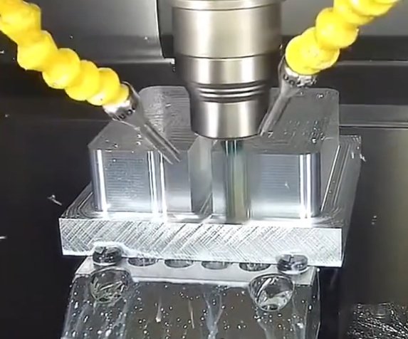
CNC cutting tools are designed for controlled material removal under programmed conditions of speed, feed, and depth of cut. They convert spindle power and feed motion into chip formation and heat.
Basic Functions
- Penetrate and shear material to form chips
- Maintain dimensional accuracy and geometric tolerances
- Generate specified surface finish and texture
- Remain stable against vibration and deflection
The performance of a cutting tool is determined by the interaction of tool material, cutting edge geometry, tool holding rigidity, machine-tool capability, and cutting parameters.
Key Performance Indicators
Typical metrics to evaluate CNC cutting tools include:
- Tool life (minutes of cutting time or number of parts per edge)
- Wear pattern and stability of wear progression
- Surface roughness and presence of defects on the workpiece
- Dimensional stability during tool life
- Chip control and evacuation quality
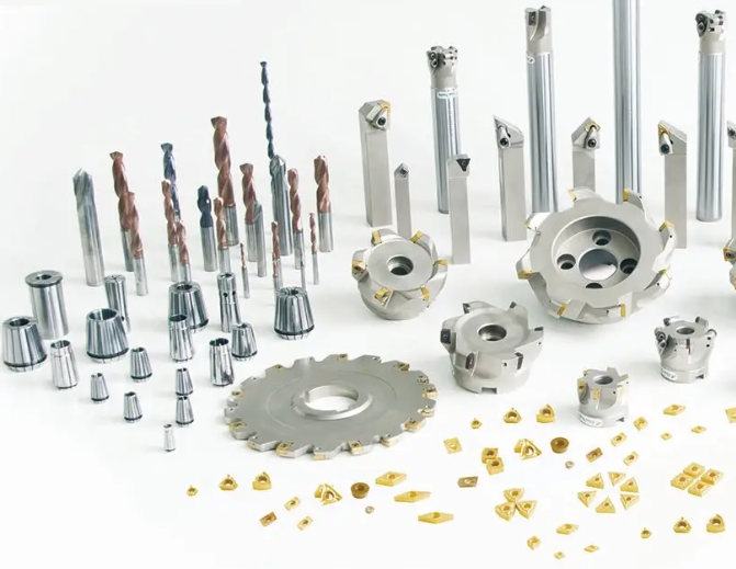
Major Types of CNC Cutting Tools
CNC cutting tools can be categorized by machining process, structure, and cutting action. Each type is optimized for specific machine tools and operations.
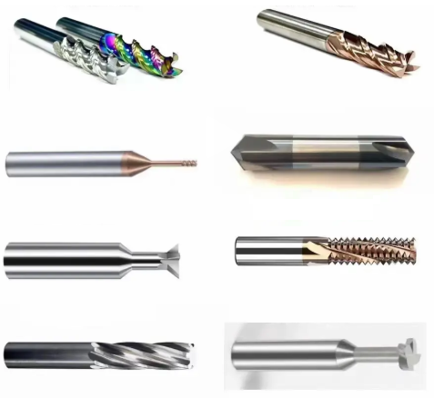
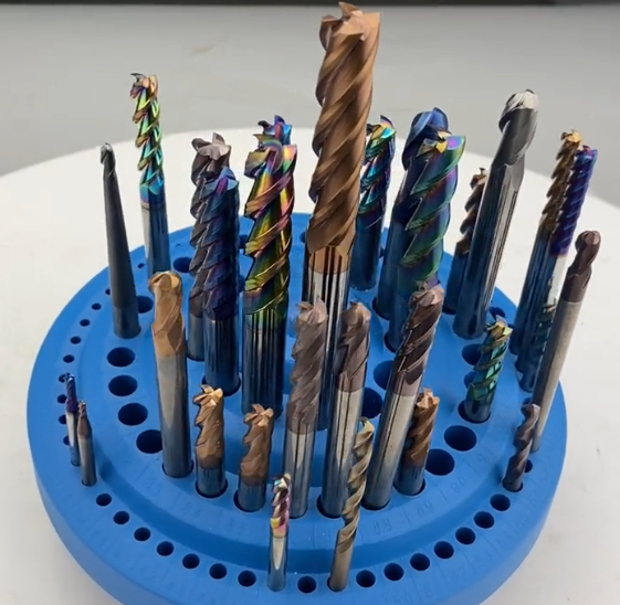
Milling Tools
Milling tools remove material via rotating multi-tooth cutters. Common CNC milling tools include:
- End mills: flat, ball, corner radius, and tapered designs
- Face mills: for planar surfaces and high metal removal
- Slot and side mills: for keyways, T-slots, and deep slots
- Form milling cutters: for specific profiles and contours
End mills are widely used in 3-axis and multi-axis machining centers for contouring, pocketing, and 3D surface machining. Face mills are used for high-efficiency facing of large planar surfaces on castings and plates.
Turning Tools
Turning tools are used on CNC lathes and turning centers. They typically consist of a tool holder and an indexable insert. Main categories:
- External turning tools: longitudinal turning, facing, profiling
- Internal turning/boring tools: for bores and internal profiles
- Parting and grooving tools: for cut-off and grooves
- Threading tools: for external and internal threads
Indexable inserts with standardized geometries and chipbreakers are clamped into holders, enabling quick indexing and repeatable positioning.
Drilling and Hole-Making Tools
Hole-making tools support drilling, reaming, boring, and hole finishing:
- Twist drills: solid and indexable types
- Center drills and spotting drills
- Step drills and core drills
- Reamers: for high-accuracy hole sizing
- Boring tools: adjustable and fine-boring heads
For deep holes, special drills with internal coolant channels and optimized flute geometry are used to maintain chip evacuation and dimensional stability.
Threading and Tapping Tools
CNC threading tools form or cut threads in turning and milling operations. Typical tools include:
- Threading inserts for lathes
- Solid thread mills for internal and external threads on machining centers
- Taps: spiral flute, spiral point, and straight flute designs
Thread mills allow one tool to cut different thread diameters within the same pitch, while taps are dedicated tools with fixed diameter and pitch.
Specialized CNC Tools
Specialized tools address particular machining tasks and materials:
- Form tools for complex profiles and repeated features
- PCD (polycrystalline diamond) tools for non-ferrous and abrasive composites
- PCBN (polycrystalline cubic boron nitride) tools for hardened steels and cast irons
- Combination tools integrating multiple steps (drill-chamfer, drill-tap)
These tools are used when standard tools cannot efficiently meet accuracy, surface, or cycle time requirements.
Tool Materials for CNC Cutting Tools
Tool material selection must match workpiece material, required tool life, and cutting conditions. The most common tool material families are high-speed steel, carbide, cermet, ceramics, PCD, and PCBN.
| Tool Material | Typical Hardness Range | Thermal Resistance | Typical Workpiece Materials |
|---|---|---|---|
| High-Speed Steel (HSS) | 60–68 HRC | Up to ~600 °C | General steels, low alloys, aluminum at moderate speed |
| Cemented Carbide | ~90 HRA | Up to ~1000 °C | Carbon steels, alloy steels, cast iron, stainless steels, non-ferrous |
| Cermet | 88–92 HRA | High, with good hot hardness | Finishing of steels and cast irons |
| Ceramic | ~93 HRA | Very high, up to ~1200 °C | Cast iron, hardened steels (finishing), high-speed cutting |
| PCD | ~6000–8000 HV | Very high | Aluminum alloys, copper alloys, composites, non-ferrous materials |
| PCBN | ~3000–5000 HV | Very high | Hardened steels, high-strength cast iron, wear-resistant alloys |
High-Speed Steel (HSS)
HSS tools offer good toughness and are widely used for drills, taps, and small cutters where stiffness and shock resistance are important. They are suitable for lower cutting speeds and intermittent cuts. Coated HSS (TiN, TiAlN) extends tool life and increases allowable cutting speed.
Cemented Carbide
Cemented carbide tools are the primary choice for CNC milling and turning due to their high hardness and thermal resistance. They are produced as solid tools (end mills, drills) or as indexable inserts.
Important carbide parameters include:
- Cobalt content: influences toughness vs. hardness
- Grain size: submicron grains for finishing, coarser grains for roughing
- Coating type: TiN, TiCN, TiAlN, AlTiN, multilayer PVD/CVD coatings
Cermet, Ceramic, PCD, and PCBN
Cermet tools balance wear resistance and surface finish, making them suitable for finishing operations in steel and cast iron.
Ceramic cutting tools can operate at high speeds with cast irons and hardened steels in continuous cuts, where their brittleness is not critical. They require stable machine conditions and rigid setups.
PCD tools are used for high-speed machining of non-ferrous metals and composites, providing long tool life and high-quality surfaces. PCBN tools are designed for hard turning and finishing of hardened steels as an alternative to grinding.
Cutting Tool Geometry and Nomenclature
Tool geometry directly affects cutting forces, chip formation, and surface quality. Geometric parameters must be adapted to material, operation type, and machine rigidity.
Fundamental Angles
Common angles used to define cutting edges include:
- Rake angle (γ): controls chip flow and cutting forces
- Relief or clearance angle (α): prevents rubbing and reduces friction
- Cutting edge angle (κ): influences direction of cutting forces
- Inclination and helix angle: affects chip evacuation and surface finish
Optimized combinations of these angles are defined differently for milling, turning, and drilling tools, and for various workpiece materials.
Insert Geometry Codes
Indexable inserts are standardized by ISO codes to indicate shape, clearance angle, tolerance, size, thickness, corner radius, and other characteristics. For example, typical shapes are coded as C (80° rhombic), D (55° rhombic), S (square), T (triangle), and so on.
Chipbreaker geometries on inserts are designed to control chip flow at defined ranges of feed and depth of cut, improving chip breaking, reducing heat concentration, and stabilizing cutting forces.
Edge Preparation
Cutting edges may be ground, honed, or chamfered. Edge preparation affects edge strength and cutting performance:
- Sharp edges: for low cutting forces and soft materials, but shorter life
- Honed edges: improve stability in tougher materials
- Chamfered edges: increase strength in heavy roughing operations
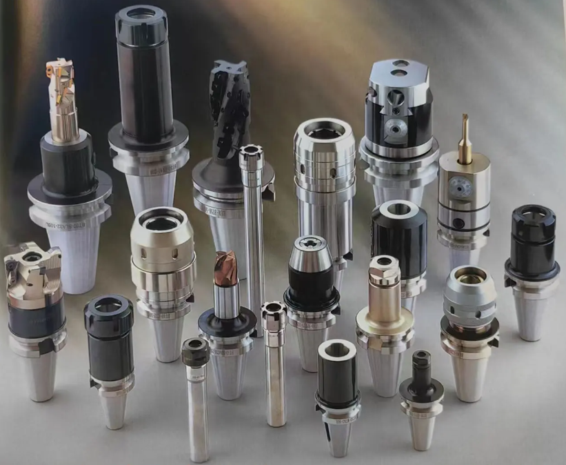
Tool Holders and Tooling Systems
Tool holders and tooling systems connect cutting tools to the machine spindle or turret. Their precision and rigidity are essential for consistent machining performance.
Common Shank and Taper Systems
Typical shank and taper standards for CNC machines include:
- BT and CAT (V-flange) tapers
- HSK tapers for high-speed, high-precision applications
- DIN and ISO metric tapers
The interface design affects runout, clamping force, and tool change accuracy. HSK holders provide high stiffness and improved repeatability at high spindle speeds due to dual-contact design (taper and face).
Types of Tool Holders
For milling and drilling, common holders are:
- Collet chucks: versatile, moderate runout
- Hydraulic chucks: high precision, good damping
- Shrink-fit holders: high concentricity and rigidity
- Side-lock (weldon) holders: secure clamping for heavy milling
For turning, tool holders are designed to accept standardized inserts with specific clamping systems such as top clamp, screw clamp, and lever clamp. Boring bars and internal holders must also control vibration in deep bores, often using damping designs.
Cutting Parameters and Machining Conditions
The main adjustable cutting parameters are cutting speed, feed rate, and depth of cut. Correct parameter selection is crucial to achieve target tool life, surface finish, and productivity.
Cutting Speed (Vc)
Cutting speed is the circumferential speed at the cutting edge, usually expressed in m/min or sfm. It is calculated as:
Vc = (π × D × n) / 1000 (for m/min, D in mm, n in rpm)
Recommended cutting speeds depend on tool material, workpiece material, and operation type (roughing vs finishing). Exceeding recommended values may lead to rapid wear or edge chipping.
Feed Rate and Feed per Tooth
Feed rate (vf) is the linear speed at which the tool advances relative to the workpiece. In milling, a more specific parameter is feed per tooth (fz):
vf = fz × z × n
where z is number of teeth and n is spindle speed.
Feed per revolution (fn) is used in turning and drilling. Feed values influence chip thickness, cutting forces, and surface finish. Too low a feed can cause rubbing; too high can overload the cutting edge.
Depth of Cut and Width of Cut
Depth of cut (ap) and width of cut (ae) define chip cross-section in milling, and depth of cut defines radial engagement in turning. Roughing operations usually use higher ap and ae, while finishing uses lower values to achieve better accuracy and surface quality.
Coolant and Lubrication
Cutting fluids control temperature, lubricate cutting zones, and aid chip evacuation. Usage patterns include:
- Flood coolant with water-soluble emulsions
- Minimum quantity lubrication (MQL)
- High-pressure coolant through tool channels
- Dry machining in suitable operations and materials
Internal coolant channels in drills, end mills, and inserts are commonly used to improve chip evacuation and reduce thermal load at the cutting edge.
Selection of CNC Cutting Tools
Choosing appropriate CNC cutting tools requires simultaneous consideration of machine capabilities, workpiece material, required tolerances, surface finish, and production volume.
Selection by Workpiece Material
Each workpiece material group requires specific tool materials, coatings, and geometries for stable cutting.
| Workpiece Material | Recommended Tool Material | Typical Coatings | Geometry Considerations |
|---|---|---|---|
| Low-Carbon Steel | Carbide | TiCN, TiAlN | Moderate positive rake, standard chipbreaker |
| Alloy Steel | Carbide, Cermet (finishing) | TiAlN, AlTiN | Strong edge preparation, stable chip control |
| Stainless Steel | Carbide | TiAlN, nano-composite coatings | High positive rake, optimized chipbreaker for adhesion control |
| Cast Iron | Carbide, Ceramic | TiN, TiCN, Al2O3-based | Negative rake insert for heavy cutting, robust edges |
| Aluminum Alloys | Carbide, PCD | Uncoated or DLC-type | Sharp edges, high helix, polished flutes |
| Hardened Steel (> 50 HRC) | PCBN, Ceramic (finishing) | Specialized high-heat coatings | Small nose radius, stable clamping, low depth of cut |
Tool Selection by Operation Type
Typical guidelines:
- Roughing: strong tools with robust edge prep, high feed and depth of cut
- Semi-finishing: balanced geometry, intermediate parameters
- Finishing: sharp edges, small nose radii, lower depth and feed for better finish
In high-volume production, indexable tools with multiple cutting edges per insert are favored. For small batch or complex shapes, solid carbide tools provide flexibility and accuracy.
Pain Points in Tool Selection
Frequent issues during tool selection include incorrect combination of tool and workpiece material leading to excessive wear, underestimation of machine rigidity causing vibration and poor surface quality, and choosing tools without considering coolant supply and chip evacuation in deep cavities or bores. Systematic review of these factors reduces risk of unstable machining and unplanned tool changes.
Tool Life, Tool Wear and Monitoring
Tool life represents the usable cutting time before a tool must be replaced due to wear or damage. Controlled wear is acceptable, while sudden failure must be avoided.
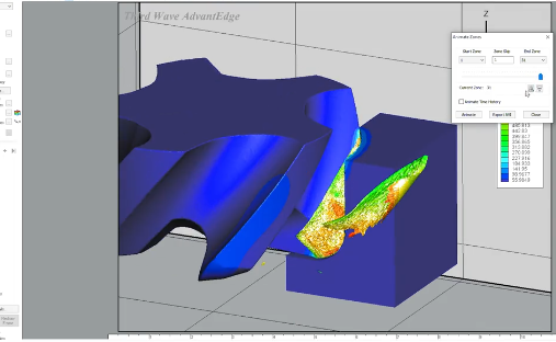
Types of Tool Wear
Common wear types include:
- Flank wear: gradual wear on clearance face; usually defines tool life
- Crater wear: wear on rake face from chip flow; influenced by cutting speed
- Notch wear: localized wear at depth-of-cut line
- Edge chipping and fracture: caused by excessive load or vibration
Wear is evaluated with optical tools or microscopes. Specific maximum wear widths or crater depths are defined as tool life criteria for a given process.
Monitoring and Replacement Strategies
Tool monitoring can be manual, semi-automatic, or fully integrated into CNC systems. Methods include measuring cutting time, counting produced parts, and using sensor-based monitoring for cutting forces, spindle load, vibration, or acoustic signals.
Controlled tool change intervals prevent sudden breakage that can damage workpieces, fixtures, and machine components.
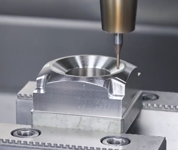
Surface Quality and Dimensional Accuracy
The choice of CNC cutting tools and parameters strongly influences surface roughness, form accuracy, and positional tolerances.
Factors Affecting Surface Finish
Key factors include:
- Nose radius and feed rate: define theoretical surface roughness
- Tool runout: affects surface texture and dimensional accuracy
- Tool vibration: leads to chatter marks and dimensional instability
- Tool wear: alters geometry and increases roughness over time
Finishing tools often have smaller nose radii, higher rake angles, and refined edge preparation to minimize cutting forces and achieve better surface quality.
Dimensional Control
Dimensional accuracy is influenced by tool deflection, thermal expansion, and runout. Using rigid toolholders, short tool overhangs, and appropriate cutting parameters reduces deflection. Compensation strategies such as tool offset adjustment and in-process measurement are implemented to maintain tolerances over extended production runs.
Chip Control and Evacuation
Effective chip control is essential to maintain continuous automated machining without tool or machine damage. Chip volume, shape, and flow are determined by tool geometry and cutting parameters.
Chipbreaker Design
Chipbreakers on inserts are engineered to control chip thickness and curvature within specified feed and depth ranges. They force chips to curl and break into manageable segments. Different chipbreakers are optimized for roughing, medium, and finishing applications.
Evacuation in Deep Cavities and Holes
In deep pocket milling or deep-hole drilling, chips must be evacuated vertically or through restricted passages. Internal coolant channels and adequate coolant pressure are used to transport chips away from the cutting zone. Tool paths can be designed with pecking cycles or helical strategies to aid chip removal.
Programming Considerations for CNC Cutting Tools
CAM programming and CNC coding must respect tool specifications and constraints to achieve stable machining.
Tool Libraries and Data
Tool libraries in CAM systems store key tool data, including diameter, length, corner radius, holder type, and recommended cutting parameters. Accurate tool definition ensures collision-free tool paths and correct simulation of material removal.
Tool Length and Radius Compensation
CNC controls use tool length compensation (e.g., G43) and radius compensation (e.g., G41/G42) to adjust paths for actual tool sizes. Accurate measurement of tool length and diameter is critical to prevent machining errors and collisions.
Maintenance, Handling and Storage of CNC Cutting Tools
Proper handling and storage extend tool life and preserve performance characteristics.
Handling Practices
Cutting edges must be protected from impact and contamination. Tools should be handled with care, avoiding contact between edges and hard surfaces. Clamping surfaces on tool holders and tools must be kept clean to maintain concentricity and clamping force.
Storage and Identification
Tool storage systems use racks, trays, and cabinets with individual compartments to prevent damage. Identification by labels, barcodes, or RFID tags supports tool tracking and inventory control.
Safety Considerations in CNC Tool Usage
CNC cutting tools operate at high speeds and generate chips and heat. Proper safety practices are required to protect personnel and equipment.
Personal Protective Measures
Operators should use safety glasses or face shields, gloves suitable for handling tools (not while operating rotating machinery), and appropriate clothing. Guarding around work zones must be in place, and machine doors should remain closed during automatic operation.
Machine and Tool Safety
Tools must be correctly clamped, and maximum speed ratings for tool assemblies must not be exceeded. Pre-use inspection of tool holders and cutting tools ensures that damaged components are not used. Correct programming and verification help avoid tool crashes.
FAQ about CNC Cutting Tools
What are CNC cutting tools?
CNC cutting tools are specialized tools used in CNC (Computer Numerical Control) machines to remove material from a workpiece. They are designed for high precision, consistency, and efficiency in machining operations such as milling, turning, drilling, and grinding.
What are the most common types of CNC cutting tools?
Common CNC cutting tools include end mills, drill bits, turning inserts, face mills, reamers, taps, and boring tools. Each type is designed for specific machining operations and materials.
How do I choose the right CNC cutting tool for my application?
Selecting the right CNC cutting tool depends on the material being machined, the required tolerance, surface finish, cutting speed, and machine capability. Tool geometry, coating, and tool material (such as carbide or high-speed steel) also play a critical role.
What materials are CNC cutting tools typically made from?
CNC cutting tools are commonly made from carbide, high-speed steel (HSS), ceramic, cermet, cubic boron nitride (CBN), and polycrystalline diamond (PCD). Carbide tools are the most widely used due to their hardness and wear resistance.
What is the main difference between solid carbide and indexable tools?
Solid carbide tools are monolithic and typically used for smaller diameters and complex geometries such as small end mills and micro drills. They offer high rigidity and precision. Indexable tools use replaceable inserts clamped in a steel body, allowing multiple cutting edges per insert and economical replacement for larger diameters and higher metal removal rates. The choice depends on tool size, operation type, required flexibility, and production volume.
