
CNC machining is one of the most reliable and repeatable ways to build functional prototypes and low-volume parts. This guide explains how CNC prototype cost is formed, what affects delivery speed, how to choose materials, and how to design parts that are practical to machine and verify.
What Is CNC Prototyping
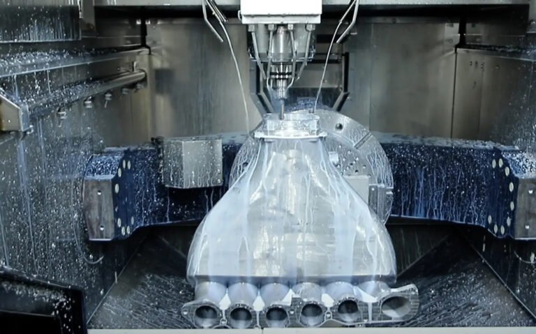
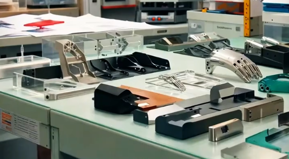
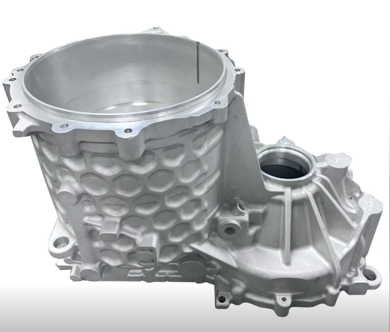
CNC prototyping is the use of computer numerical control (CNC) machining processes such as milling and turning to manufacture one-off or low-quantity parts directly from digital 3D CAD models. It is commonly used for mechanical prototypes, fit-check parts, functional test pieces and small pilot runs.
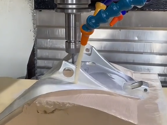
CNC machines remove material from solid stock (metal, plastic or other machinable materials) using cutting tools. Toolpaths are generated from the CAD model and executed by CNC machine controllers, which allows repeatable accuracy and good dimensional control even for complex geometries.
Key Factors That Determine CNC Prototype Cost
CNC prototype pricing is built from several technical and commercial factors. Understanding these allows engineers to estimate cost early and adjust designs or order strategies before sending parts for quotation.
Machining Time
Machining time is often the largest single cost driver. It includes roughing, semi-finishing, finishing and any necessary re-fixturing operations. Machine shops estimate time based on toolpath simulations, experience, and part complexity. Longer cutting time directly increases machine-hour charges and tool wear.
Setup and Programming
Setups include workholding design, fixture installation, tool selection, tool length offset setting and trial cutting. Programming includes CAM work, post-processing and verifying toolpaths. Complex prototype parts that require multiple setups, fixtures or 5-axis strategies will have higher non-recurring engineering (NRE) cost per part, especially for very low quantities.
Material Type and Stock Size
Material cost has two components: raw stock price and the amount of material removed. Metals like titanium, Inconel or hardened steel are more expensive to purchase and machine than common aluminum alloys or standard plastics. Large blocks that require heavy roughing also add cost through longer cycle times and higher tool wear.
Tolerance Requirements
Tight dimensional tolerances require more precision strategies, such as finish passes with small step-over, slower feed speeds, temperature control and post-machining inspection. Features with tolerances tighter than ±0.01 mm or ±0.0005 in typically increase cost through additional process steps, tool selection constraints and inspection time.
Surface Finish and Post-Processing
Requested surface finish has a strong impact on machining parameters. For example, achieving Ra 0.4–0.8 μm on large surfaces requires optimized tooling, higher spindle speeds and multiple finishing passes. Additional cost also comes from post-processing such as bead blasting, polishing, anodizing, plating, painting or coating.
Quantity and Part Repetition
For prototyping, quantities are usually low, but cost per piece decreases as quantity increases because setup and programming costs are amortized. When a part is repeatedly ordered, some programming and fixture costs can be reused, lowering the effective price for subsequent batches.
Typical CNC Prototype Cost Structure
The main elements of CNC pricing can be summarized as follows:
| Cost Component | Description | Typical Impact |
|---|---|---|
| Programming / CAM | Toolpath creation, post-processing, machining strategy optimization | One-time per part number; more significant at low quantities |
| Setup / Fixturing | Workholding design, fixture building, machine setup, tool setting | Scales weakly with quantity; cost per part reduces as volume increases |
| Machine Time | Active cutting, tool changes, probing cycles, part handling on machine | Directly proportional to complexity and size; often largest share |
| Material | Raw stock purchase, cutting from standard bars or plates | Varies by material type, geometry yield and stock availability |
| Tooling / Consumables | Cutters, inserts, coolant, wear and breakage | Higher for hard-to-machine materials or abrasive composites |
| Post-Processing | Deburring, surface finishing, anodizing, coating, heat treatment | Adds cost per piece; some processes have minimum batch charges |
| Inspection / QC | Dimensional checks, CMM reports, capability studies if required | Higher for tight tolerances or documented inspection requirements |
How CNC Prototype Lead Time Is Determined
Lead time for CNC prototypes is influenced by technical and logistical factors. Requesting an unrealistic schedule can drive cost up due to overtime, machine rescheduling or express logistics.
Shop Capacity and Machine Availability
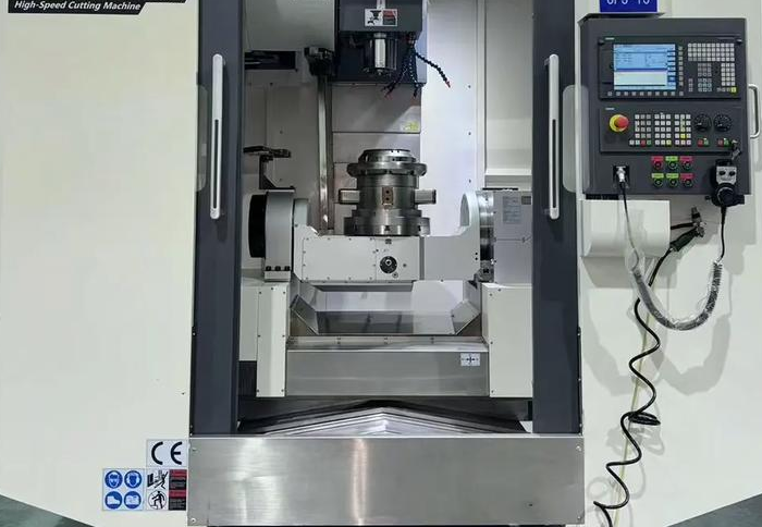
Lead time depends on current shop workload and availability of suitable machines, such as 3-axis, 4-axis, 5-axis mills or turning centers. Parts requiring specific high-end equipment or long uninterrupted cycles may compete with production jobs and affect schedule.
Programming and Process Planning Time
Complex geometries, intricate pockets, undercuts or 5-axis surfaces take longer to program and validate. If process planning requires fixture design or multi-part nesting, lead time increases even when actual machining time is moderate.
Material Procurement
Standard materials like 6061-T6 aluminum or 304 stainless steel are usually available from stock and do not significantly affect lead time. Exotic alloys, oversized blocks or special certifications (such as aerospace traceability) may require extended purchasing time.
Post-Processing Queue
External finishing vendors (e.g., anodizing or plating facilities) often work in batches. Parts may need to align with their process schedules, adding a few days. Heat treatment cycles also have fixed durations and cannot be significantly shortened.
Inspection and Documentation
Basic dimensional checks can be completed quickly. However, full CMM inspection, first article inspection reports or custom measurement documentation can add several days, especially if measurement fixtures or custom programs must be prepared.
Material Selection Guide for CNC Prototypes
Material choice affects machinability, mechanical behavior, thermal stability, weight, corrosion resistance and cost. Selecting a practical material for prototyping can significantly reduce both lead time and budget.
Common Metals for CNC Prototypes
Metal prototypes are preferred for structural, thermal or wear applications. The following table summarizes typical choices and their characteristics.
| Material | Typical Use | Machinability | Notes |
|---|---|---|---|
| Aluminum 6061-T6 | General prototypes, enclosures, brackets | Excellent | Good strength-to-weight, low cost, widely stocked |
| Aluminum 7075-T6 | High-strength prototypes, aerospace components | Good | Higher strength than 6061, slightly more expensive |
| Stainless Steel 304 | Corrosion-resistant parts, food-contact components | Moderate | Austenitic stainless; work hardening requires proper tooling |
| Stainless Steel 316 | Marine, chemical and medical environments | Moderate to low | Better corrosion resistance; higher cutting forces |
| Carbon Steel 1018 | Structural parts, shafts, fixtures | Good | Economical; may require coating or painting for corrosion protection |
| Brass (e.g., C360) | Precision fittings, connectors, aesthetic parts | Excellent | Very good machinability and surface finish; higher material price |
| Copper | Thermal management, electrical components | Moderate to low | High thermal conductivity; can be challenging due to gumminess |
| Titanium Grade 5 (Ti-6Al-4V) | High strength, lightweight, aerospace and medical parts | Low | High material and machining cost; used when performance justifies |
Common Plastics for CNC Prototypes
Plastics are suitable for lightweight components, insulation, fluid handling and many functional prototypes.
- ABS: Good impact resistance, machinable, widely used for housings and fixtures.
- Delrin (POM): Low friction, good dimensional stability, used for gears and bearings.
- Nylon (PA): Tough, wear-resistant; can absorb moisture, which affects dimensions.
- Polycarbonate (PC): High impact strength, transparent, used in protective covers.
- PEEK: High temperature and chemical resistance, suitable for demanding environments.
- HDPE / UHMW-PE: Very low friction, good for sliders, wear strips and impact surfaces.
Plastic machining parameters differ significantly from metals. Tool geometry, cutting speed and coolant selection are adjusted to avoid melting, chipping or surface tearing.
Recommended Tolerances for CNC Prototypes
CNC machining can normally achieve tight tolerances, but specifying unnecessarily strict tolerances increases cost and lead time. It is important to define tolerances based on functional requirements rather than defaults.
General Machined Features
For most prototype applications, the following ranges are practical:
- Standard linear features: ±0.05 mm to ±0.1 mm (±0.002 in to ±0.004 in).
- Critical features: ±0.01 mm to ±0.02 mm (±0.0004 in to ±0.0008 in), by agreement.
- Hole diameters up to 10 mm: typically ±0.02 mm with standard drills and reamers.
- Flatness on small surfaces: within 0.05 mm, depending on part size and fixturing.
Capabilities depend on machine condition, fixturing strategy, measurement equipment and material stability.
Geometric Dimensioning and Tolerancing (GD&T)
GD&T can specify form, orientation and location tolerances in a clear way. When using GD&T for prototypes:
Use the following guidelines:
Define datums consistently and avoid over-constraining features. Reserve very tight position or flatness tolerances for surfaces that are functionally critical. Communicate whether all features require full inspection or only a subset is critical for prototype evaluation.
Surface Finish Options for CNC Prototypes
Surface finish affects appearance, friction, sealing performance and subsequent processes such as painting or bonding. All machined parts have tooling marks; additional finishing steps modify the texture as needed.
As-Machined Surface
As-machined surfaces are produced directly by cutting tools. Typical roughness values for standard finishing passes range around Ra 1.6–3.2 μm, depending on material, toolpath, feed rate and tool condition. As-machined parts are common for internal components and functional prototypes where appearance is not critical.
Bead Blasting
Bead blasting uses glass or ceramic beads to create a uniform matte texture. It removes small burrs and minimizes tool mark visibility. Surface roughness usually becomes higher than fine milling, but the appearance is consistent. Bead blasting is frequently applied before anodizing aluminum parts.
Anodizing and Plating
Anodizing is typically used on aluminum prototypes for improved corrosion resistance and aesthetics. Type II sulfuric anodizing offers a range of colors, while Type III hard anodizing provides thicker, more wear-resistant layers. Plating methods like nickel or chrome plating are used for corrosion protection, conductivity, or decorative finishes on metals.
Polishing and Brushing
Polishing gradually refines surfaces using abrasives to reduce roughness and increase gloss. Brushing creates fine, directional lines suitable for visible surfaces on consumer products or decorative components. Both processes can be localized to specific surfaces of a prototype.
Design Considerations for Cost-Effective CNC Prototypes
Design for manufacturability (DFM) improves the feasibility and cost profile of CNC prototypes. Early attention to geometry, tolerances and material can prevent complications after quotation.
Cutter Access and Minimum Radii
Internal corners cannot be perfectly sharp because rotary tools have finite diameters. When designing pockets or channels, ensure that corner radii are equal to or greater than the radius of the smallest intended cutter. Extremely small radii increase machining time and tool breakage risk.
Feature Depth and Aspect Ratio
Deep pockets and tall walls can cause chatter, deflection and dimensional error. As a general guideline, maintain depth-to-diameter ratios for end mills within practical limits. Very deep slots may require multiple tool sizes and strategies, which increases machine time and cost.
Wall Thickness and Rigidity
Thin walls are prone to vibration and distortion. When possible, keep wall thickness within stable ranges relative to the material. For prototypes, consistency and dimensional stability are often more useful than minimum possible weight, especially in early design iterations.
Threading and Small Features
Thread size, depth and location influence tooling selection. Small threaded features may require taps or thread milling tools that are more fragile and slower to use. For screw connections in prototypes, consider using commonly available thread sizes and avoid unnecessary thread depth.
Comparing CNC Prototyping with Other Processes
CNC machining is one of several options for creating prototypes. Understanding its strengths relative to other methods helps with process selection.
CNC vs 3D Printing
CNC machining uses subtractive manufacturing, whereas 3D printing is additive. CNC typically offers better dimensional accuracy, surface finish, and material properties for metals and engineering plastics. 3D printing is advantageous for highly complex geometries, internal channels and lattice structures that are difficult to machine.
CNC vs Injection Molding for Prototypes
Injection molding requires mold tooling and is more economical for high quantities. For early-stage prototypes or low volumes, the tooling cost and lead time of molding are usually not justified. CNC is suitable when the objective is to test functionality, mechanical performance or assembly fit before investing in tooling.
Inspection and Quality Control for CNC Prototypes
Effective inspection ensures that CNC prototypes match the intended dimensions and functional requirements. The level of inspection can be tailored to the stage of development and the role of the prototype.
Measurement Tools and Methods
Typical inspection equipment includes calipers, micrometers, height gauges, plug gauges, coordinate measuring machines (CMM) and optical measurement systems. For critical dimensions or geometric tolerances, CMM is often used to provide detailed reports.
Inspection Scope for Different Prototype Stages
Early concept prototypes may require only basic dimensional checks on key surfaces. Later test and validation prototypes often need more complete inspection, including flatness, perpendicularity and hole location. Communicate which dimensions are critical and which are reference-only to align inspection effort with project needs.

Managing Pain Points in CNC Prototyping
Engineers and buyers frequently encounter recurring difficulties when ordering CNC prototyping. Addressing them early improves reliability and cost control.
Ambiguous or Incomplete Drawings
Missing tolerances, unclear datums, or conflicting information between 3D models and 2D drawings cause delays or interpretation errors. Provide a clear tolerance schema, consistent units and notes for special requirements such as deburring or edge breaks.
Unrealistic Delivery Expectations
Requesting extremely short lead times for complex parts can result in higher costs and scheduling conflicts. Planning prototype orders in alignment with design milestones allows more competitive pricing and reduces the risk of quality compromise.
Material and Finish Over-Specification
Choosing high-grade materials or demanding cosmetic finishes not required for the prototype's purpose increases cost and lead time. Use simpler materials or finishes for internal tests and reserve advanced specifications for validation stages where these properties are critical.
FAQ: CNC Prototypes, Cost and Materials
What is a CNC prototype?
A CNC prototype is a part or product made using Computer Numerical Control (CNC) machining. It allows designers and engineers to test the functionality, fit, and design of a part before mass production.
What materials can be used for CNC prototypes?
CNC prototypes can be made from metals (aluminum, steel, titanium, brass), plastics (ABS, PEEK, acrylic), and sometimes composite materials depending on the machining capabilities.
How much does a typical CNC prototype cost?
The cost of a CNC prototype varies widely based on geometry, material, tolerances and quantity. Simple small aluminum parts can fall near the lower range of pricing, while large, complex multi-setup components in difficult materials cost significantly more. To estimate, consider programming and setup as a fixed base cost and add material and machining time as variable components. Providing a detailed 3D model, 2D drawing and target quantity helps suppliers quote accurately.
Can CNC prototypes be used for functional testing?
Yes. CNC prototypes are often strong enough to be used for functional, mechanical, or assembly testing, depending on the material selected.
What file formats are needed for CNC prototyping?
Commonly accepted formats include STEP (.step/.stp), IGES (.iges/.igs), STL, and sometimes DXF for 2D profiles. Make sure your design is clean and free of errors for machining.
