
Sensors convert physical quantities such as pressure, temperature, displacement, force or acceleration into electrical signals. Their performance depends not only on the sensing element but also on the mechanical structure and machining quality of housings, supports, diaphragms and interfaces. This article explains common sensor structures and the associated machining practices required to achieve high accuracy, stability and durability.
Fundamental Structural Concepts in Sensors
Most sensor types share a set of structural building blocks. Understanding these enables consistent design and machining strategies across different applications.
Transduction Element and Mechanical Support
The transduction element (e.g., strain gauge, piezoelectric crystal, MEMS die, RTD, thermistor) requires a mechanically stable support. Key features include:
- Rigid base or substrate with controlled flatness and surface finish.
- Defined stress paths so that applied loads or pressures reach the sensing element without excessive damping or distortion.
- Isolation from external mechanical shocks and vibrations when necessary.
Machining of the support structure focuses on accurate datum surfaces, precise alignment features (steps, shoulders, pins, slots) and repeatable mounting geometries for assembly and calibration.
Load Transfer and Sensing Interfaces
Many sensors measure force, pressure, torque, or displacement. The structure must transfer the measurand to the sensing element with minimal loss or parasitic effects. Typical features include:
- Beams, diaphragms or membranes for strain-based sensing.
- Flexures or hinges that provide controlled compliance.
- Coupling interfaces (threads, flanges, shafts) to connect to the measured system.
Machining quality directly affects stiffness, strain distribution, linearity and repeatability. Uniform cross sections, smooth transitions, and carefully radiused fillets are required to avoid unintended stress concentrations.
Housing, Protection and Interfaces
The housing protects the sensing element from environmental influences and provides mechanical interfaces for installation and wiring. Common requirements are:
- Mechanical robustness against impact, vibration and overload.
- Environmental protection (IP rating, corrosion resistance, thermal management).
- Electrical interface via connectors, terminals or cable glands.
Machining tasks include forming the main body from bar, tube or forging; adding ports, recesses and mounting features; and ensuring consistent wall thickness where thermal gradients may impact measurement stability.
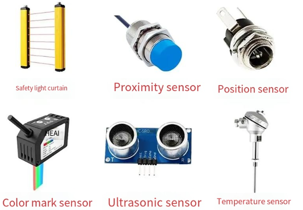
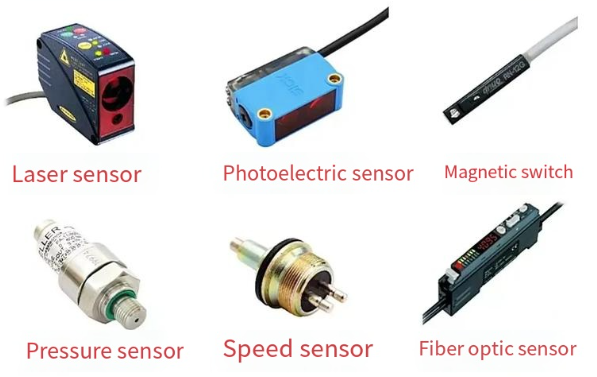
Typical Sensor Structures by Application
Each sensor category uses specific structural forms. Machining must match these forms and the associated tolerances.
Pressure Sensor Structures
Pressure sensors commonly measure absolute, gauge or differential pressure through a diaphragm or membrane. Typical structure:
Core components include:
1) Process connection: threaded or flanged port exposing the diaphragm to the process medium.
2) Diaphragm assembly: thin metallic or silicon diaphragm bonded or welded into a cavity.
3) Sensor cavity: reference chamber for gauge or absolute pressure.
4) Sensor element: piezoresistive, capacitive or strain-based chip attached to the diaphragm or support.
5) Housing and connector: package for electronics and electrical output.
Machining aspects:
- Process port: often turned and milled from stainless steel or other corrosion-resistant alloys, with tapered or straight threads according to regional standards. Surface finish inside sealing regions must avoid scratches or tool marks.
- Diaphragm seat: flatness and perpendicularity control the uniformity of diaphragm clamping. Machined shoulders and grooves locate the diaphragm and weld bead.
- Cavity geometry: depths and diameters affect the reference volume and stiffness. Boring and reaming operations are used for tight cylindrical tolerances.
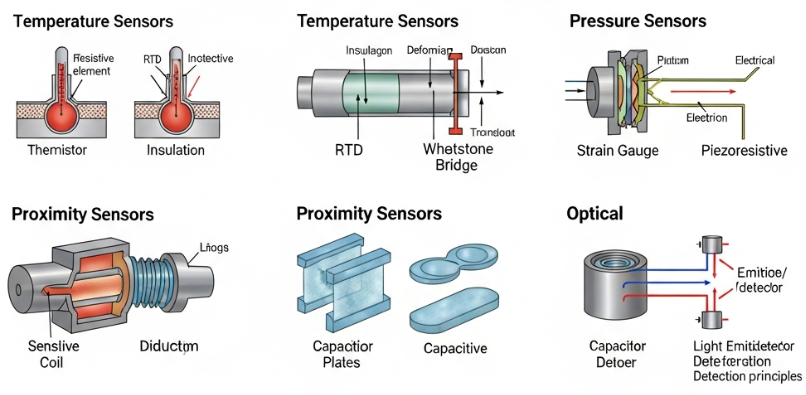
Temperature Sensor Structures
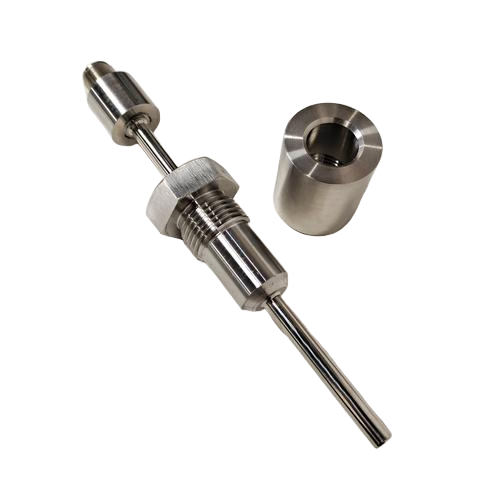
Temperature sensors (RTDs, thermocouples, thermistors) often follow simpler mechanical structures but require precise positioning within protective sheaths.
Common design elements:
- Probe tube or sheath: stainless steel or high-temperature alloy tube with specified outer and inner diameters, length and straightness.
- Tip geometry: flat, hemispherical or tapered tip to tailor response time and mechanical strength.
- Sensor mounting: ceramic or mica supports, powder filling, or mineral-insulated cable termination.
Machining requirements include:
- Turning the probe body to defined diameters and tolerances for insertion into thermowells or process ports.
- Finishing the tip to a smooth surface and controlled wall thickness to balance response speed and durability.
- Machined shoulders and threads for process connection or compression fittings.
Strain Gauge and Load Cell Structures
Load cells and force sensors use strain gauges bonded to an elastic element. Structural forms include bending beams, shear beams, S-beams, ring load cells and single-point platforms.
Key structural features:
- Elastic element: machined from alloy steel, stainless steel or aluminum with controlled cross sections.
- Gauge areas: regions of concentrated, uniform strain where strain gauges are bonded.
- Overload stops: mechanical stops limiting maximum deflection.
- Mounting surfaces: flat, parallel faces with precise hole patterns.
Machining priorities:
- Achieving tight thickness tolerances in beam regions to control sensitivity and rated capacity.
- Smooth blending of cross-sectional changes to minimize stress concentrations.
- Ensuring flatness, parallelism and hole-position accuracy on mounting faces for reproducible load introduction.
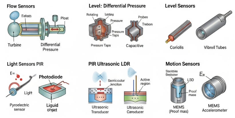
Position and Displacement Sensor Structures
Linear and rotary position sensors (LVDTs, potentiometric sensors, encoders, Hall-based sensors) rely on precise alignment and controlled clearances.
Structural aspects:
- Guide tubes or housings with internal bores for cores or moving shafts.
- End caps and bearings that define movement limits and alignment.
- Slots or reliefs for magnetic fields and coil placement in inductive designs.
Machining focuses on:
- Generating accurate bores with low runout to ensure concentric motion.
- Maintaining tight tolerances on shaft and bore diameters for low friction and minimal play.
- Creating precise grooves and mounting features for coils, magnets or scale strips.
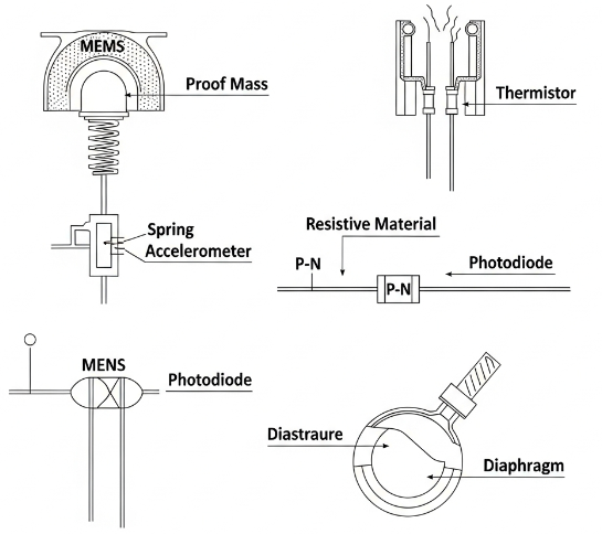
MEMS and Miniature Sensor Packaging Structures
MEMS sensors employ micromachined silicon dies within metal or plastic packages that provide mechanical protection and environmental interfacing.
Common structure:
- Leadframe or substrate: supports the die and provides electrical interconnection.
- Cavity or cap: protects the MEMS structure while allowing pressure, acceleration or sound to reach the die.
- Ports or acoustic openings: machined or molded features that connect the external environment to the MEMS surface.
Machining is most relevant for metal caps, housings and adapter pieces, which require:
- Precision drilling or laser machining of small ports with controlled diameter and surface quality.
- Accurate seating surfaces for hermetic sealing to ceramic or metal substrates.
- Fine tolerances for alignment relative to the MEMS die where directional sensitivity is critical.
Mechanical Design Considerations for Sensor Structures
Mechanical design determines how machining operations are specified. Structural integrity, metrological performance and manufacturability must be harmonized.
Geometry, Stiffness and Strain Distribution
Geometry defines how mechanical loads and pressures distribute over the structure. Key design goals are:
- Sufficient stiffness to avoid excessive deflection, while maintaining measurable strain at the sensor element.
- Smooth stress gradients, avoiding sharp corners and abrupt cross-sectional changes.
- Symmetry where possible to minimize thermal and mechanical biases.
Typical geometric design practices:
- Use fillet radii at internal corners to reduce stress concentration factors.
- Maintain constant or slowly varying cross sections in beam and diaphragm regions.
- Provide stiff reference sections near mounting points to reduce bending under off-axis loads.
Tolerances, Fits and Datum Strategy
Tolerancing governs the reproducibility of sensor performance and assembly. Particularly important features include:
- Reference datums for alignment of sensing elements and mounting interfaces.
- Fits between shafts and bores in rotating or sliding sensors (clearance, transition or interference fits as appropriate).
- Flatness and parallelism of sealing and mounting surfaces.
Typical tolerance ranges:
- Diameter tolerances for precision fits: ±0.005 mm to ±0.02 mm depending on size and application.
- Flatness on critical mounting surfaces: 0.01 mm to 0.05 mm over typical load cell or sensor base dimensions.
- Perpendicularity of threaded process connections to sensor axes: often within 0.1° to ensure load alignment.
Surface Finish and Contact Quality
Surface quality affects sealing, fatigue life, friction and signal stability. Appropriate surface roughness (Ra) must be specified:
- Sealing surfaces with elastomer O-rings: usually Ra 0.8–3.2 µm, depending on seal type.
- Metal-to-metal gaskets: finer finishes, typically Ra ≤ 0.8 µm, with controlled waviness.
- Strain gauge bonding areas: smooth but not mirror-polished surfaces to support adhesive bonding; surface preparation via grinding or fine machining followed by cleaning.
Consistent surface finish reduces scatter in calibration results and improves long-term stability by minimizing micro-slip and fretting at interfaces.
Materials and Their Machinability in Sensor Construction
Material selection balances mechanical properties, environmental compatibility, electrical behavior and machinability.
Metals Used in Sensor Structures
Metals form the majority of housings, load-bearing elements and process connections. Common choices include:
- Stainless steels (e.g., 304, 316, 17-4PH): widely used for pressure sensors, load cells and industrial housings due to corrosion resistance and weldability.
- Alloy steels: used for high-strength load cells with protective coatings.
- Aluminum alloys: used where low mass and high machinability are required, such as single-point load cells and some housings.
- Nickel and nickel-based alloys: employed in high-temperature or highly corrosive environments.
Machinability considerations:
- Austenitic stainless steels (e.g., 316) may require lower cutting speeds and optimized tools to reduce work hardening.
- Precipitation-hardened steels (e.g., 17-4PH) can be machined in solution-treated condition and then heat-treated to final strength.
- Aluminum alloys generally allow high-speed machining and fine surface finishes with appropriate tool geometry.
Ceramics, Glass and Polymers
Non-metallic materials are used for insulation, chemical resistance or low thermal conduction.
- Technical ceramics: provide electrical insulation and high-temperature capability (e.g., alumina substrates in high-temperature sensors).
- Glass: used in feedthroughs and sealing of electrical pins in hermetic packages.
- Polymers: used for cable glands, connector housings, protective covers and integrated plastic sensor housings in automotive and consumer sensors.
Machining of these materials may involve grinding, laser machining, or molding rather than conventional metalcutting operations. Dimensional control and surface quality must still satisfy sensor design requirements.
Material Pairing and Contact Interfaces
Different materials are often combined in a single sensor (metal housing, ceramic substrate, polymer sealing). Structural design and machining must support:
- Controlled gaps and clearances at interfaces to accommodate differential thermal expansion.
- Suitable surface textures to promote adhesion in bonded joints.
- Proper transitions between machined metal and molded or sintered parts to avoid stress concentrations.
Common Machining Processes for Sensor Components
Sensor structures are produced through a combination of machining processes tailored to geometry, tolerances and materials.
Turning, Milling and Drilling
Conventional and CNC machining are widely used:
- Turning: produces cylindrical housings, threaded ports, probe stems and shafts. It is applied to bar or tube stock to create external diameters, shoulders, grooves and chamfers.
- Milling: used for flat mounting faces, slots, pockets, and complex 3D forms in load cells and housings.
- Drilling and boring: create through-holes, blind holes, cavities and internal channels for pressure, cables or fasteners.
Critical factors:
- Tool selection and cutting parameters to achieve required surface finish and dimensional accuracy.
- Sequence of operations to maintain datum integrity and minimize distortion from clamping or residual stresses.
- Use of reaming or honing where bore roundness and smoothness affect sliding components or seals.
Grinding, Lapping and Honing
Where high precision and superior surface quality are required, finishing processes are applied:
- Surface grinding: creates flat, parallel mounting surfaces for load cells or sensor bases.
- Cylindrical grinding: refines shaft and bore tolerances beyond turning capability.
- Lapping: improves flatness and surface finish on sealing faces and reference surfaces.
- Honing: enhances bore geometry for low-friction linear movement in displacement sensors.
These processes reduce micro-roughness and waviness, leading to more stable mechanical and metrological behavior.
EDM, Laser Machining and Micro-Machining
For complex features, thin diaphragms or hard materials, non-conventional machining is used:
- Electrical discharge machining (EDM): shapes tight internal radii, slots and thin webs in load cell and diaphragm structures without excessive mechanical forces.
- Wire EDM: produces precise outlines of elastic elements with controlled kerf and minimal burrs.
- Laser machining: drills micro-holes for sensor ports, vents and acoustic openings, and can cut thin metal foils.
These methods achieve geometries not easily attainable by conventional cutting while maintaining structural integrity.

Process Control and Tolerance Management in Sensor Machining
Stable sensor performance depends on consistent machining processes with controlled variation.
Dimensional Control and Measurement
Measurement systems used for verifying sensor components include:
- Coordinate measuring machines (CMM) for complex geometries and multi-axis features.
- Surface roughness testers for critical sealing and bonding surfaces.
- Profilometers and form testers for bores, shafts and diaphragm profiles.
Measurement data supports process capability analysis, ensuring that tolerances for functional features are reliably respected over production batches.
Thermal Effects and Residual Stresses
Machining can introduce thermal and mechanical stresses that may later relax, causing dimensional changes. To mitigate this:
- Rough machining is often followed by stress-relief heat treatment, then semi-finish and finish machining.
- Cutting parameters and coolant usage are selected to limit heat buildup.
- Symmetrical material removal is practiced when possible to minimize distortion in slender or thin-walled components.
For high-accuracy load cells and pressure sensors, maintaining stable mechanical geometry over time is essential for preserving calibration.
Repeatability between Batches
To achieve consistent sensor characteristics, geometrical variation must be controlled not only within a batch but between batches:
- Standardized tooling and tool offsets are maintained.
- Setup procedures and datums are documented and replicated.
- Process parameters are monitored and adjusted based on statistical feedback.
This reduces the need for extensive individual calibration adjustments and supports interchangeability of sensor modules.
Sealing, Isolation and Environmental Protection Structures
Sensors often operate in aggressive or demanding environments. Structural design and machining of sealing features are critical.
O-Ring and Gasket Grooves
Sealing grooves are machined to defined widths, depths and surface finishes. Important parameters include:
- Groove diameter and width to match O-ring cross section and compression ratio.
- Corner radii to prevent O-ring damage during assembly.
- Surface finish that supports sealing without tearing or extrusion.
Dimensional control directly affects sealing reliability and leak rates in pressure and level sensors.
Weld Preparations and Hermetic Sealing Surfaces
Welded joints and glass-to-metal seals require specific geometries:
- Weld prep grooves and chamfers to obtain full penetration and proper bead shape.
- Overlap joints for laser welding of thin diaphragms to sensor bodies.
- Smooth, clean surfaces for glass sealing around electrical pins.
Machining must avoid inclusions, deep tool marks or sharp notches that could initiate cracks under thermal or mechanical loads.
Cable Glands, Connectors and Feedthroughs
Entry points for electrical connections are structural weak points if not properly designed and machined:
- Threaded holes for cable glands must meet form and position requirements to ensure proper engagement.
- Counterbores for connector shells provide spacing and mechanical support.
- Hermetic feedthroughs require tight tolerances on hole diameters and surface quality for sealing.
These details are essential for maintaining ingress protection ratings and preventing moisture or contaminant entry.
Mounting, Alignment and Integration Structures
Sensor structures must interface reliably with machines, process lines or test setups. Mounting and alignment features enable this integration.
Mounting Flanges, Brackets and Bases
Many industrial sensors are mounted using flanges or bases with bolt patterns:
- Flatness, perpendicularity and hole positional accuracy define how loads transfer to the sensing element.
- Chamfers and radii around mounting holes reduce crack initiation risk.
- Reference edges or pins improve positional repeatability during installation.
In load cells, poor machining or deformation of mounting surfaces can significantly affect linearity and hysteresis.
Alignment Features for Directional Sensors
Accelerometers, inclinometers and directional pressure sensors require defined orientation relative to the system:
- Reference flats, keyways or alignment marks are machined on housings.
- Asymmetric bolt patterns prevent incorrect installation orientation.
- Machined reference planes support orientation during calibration and system assembly.
Accurate alignment ensures that measured axes correspond to actual movement or force directions.
Interfaces for Calibration and Testing
During production and maintenance, sensors require connection to calibration and test equipment:
- Standardized mechanical interfaces, such as threaded studs or flanges, simplify the application of reference loads or pressures.
- Machined access ports allow application of calibration pressures or connection of reference probes.
- Flat surfaces and feature references support clamping in calibration fixtures without inducing additional mechanical stress.
Representative Machined Features in Sensor Components
The table below summarizes typical machined features, their functions and key requirements.
| Feature | Typical Function | Key Machining Requirements |
|---|---|---|
| Diaphragm seat | Locating and supporting pressure diaphragm | High flatness, controlled diameter, fine surface finish for weld or seal |
| Load-bearing beam | Elastic element in load cell or force sensor | Uniform thickness, smooth transitions, precise width and height tolerances |
| Probe stem | Temperature sensor insertion into process or thermowell | Controlled OD, straightness, thread quality, tip geometry |
| Mounting face | Contact surface for installation on machine or structure | Flatness, parallelism, hole position and diameter accuracy |
| O-ring groove | Sealing for pressure port or housing cover | Accurate depth and width, correct radii, appropriate surface roughness |
| Alignment bore | Guiding moving core or shaft in displacement sensor | Roundness, cylindricity, tight diameter tolerance, low surface roughness |
| Cable gland thread | Retention and sealing of electrical cable entry | Thread form accuracy, proper chamfers, controlled engagement length |
Manufacturing Flow for Machined Sensor Components
Combining structural design and machining processes, a typical manufacturing flow for metal sensor housings or load-bearing elements is as follows:
1) Pre-Machining and Stock Preparation
Material comes as bar, forging, casting or plate. Initial operations include:
- Cutting to length via sawing or shearing.
- Rough turning or milling to remove excess material and establish basic geometry.
- Marking or definition of primary datums.
2) Rough Machining of Functional Regions
Rough cuts define cavities, ports, external shapes and mounting platforms:
- High material removal rates with allowances left for finishing.
- Stable clamping setups to avoid deformation.
- Process parameters chosen for productivity while limiting residual stresses.
3) Intermediate Heat Treatment and Stress Relief
Where necessary, parts undergo stress relief or solution treatment and aging:
- Reduces internal stresses from rough machining.
- Brings material to required hardness and mechanical properties before finish machining.
4) Finish Machining of Critical Features
Final dimensional and geometric tolerances are achieved:
- Finish turning, milling, drilling, boring and reaming of precision surfaces.
- Machining of diaphragm seats, gauge areas, sealing faces and alignment features.
- Application of grinding, lapping or honing where required.
5) Inspection and Surface Preparation
Measurement and cleaning steps include:
- Dimensional inspection of critical features using CMM or gauges.
- Surface roughness verification on specified areas.
- Cleaning to remove machining residues, oils and particles, preparing for welding, bonding or assembly.
6) Integration with Sensing Elements
After machining, mechanical parts are combined with sensing elements:
- Welding or bonding of diaphragms and substrates.
- Bonding strain gauges and routing wiring.
- Assembling connector or cable interfaces into machined ports.
Typical Issues Related to Sensor Structures and Machining
Despite careful design, several recurring issues can arise from structural or machining aspects:
| Issue | Structural / Machining Cause | Consequence for Sensor Performance |
|---|---|---|
| Non-linearity | Non-uniform strain distribution due to geometric deviations or sharp transitions | Deviation from ideal output vs. input curve, requiring more complex calibration |
| Zero shift | Residual stresses, distorted mounting surfaces or uneven clamping | Offset changes after installation or over time |
| Hysteresis | Micro-slip at contact surfaces, non-uniform contact, surface roughness effects | Different output values for increasing vs. decreasing load |
| Leakage | Poorly machined sealing grooves or surfaces, incorrect surface finish | Loss of reference pressure, ingress of media, unstable readings |
| Mechanical drift | Relaxation of stresses, insufficient stress relief, or thin sections deforming | Long-term shift of calibration, reduced accuracy |
| Mounting sensitivity | Insufficient flatness or parallelism on mounting faces, misaligned holes | Output depends strongly on installation torque or mounting conditions |
Early identification and correction of these structural and machining-related issues significantly improves reliability and reduces field adjustments.
FAQ
What are the common structural components of a sensor?
Typical sensor structures include a sensing element, substrate or housing, electrical connections, signal conditioning circuits, and protective encapsulation.
Which materials are most commonly used for sensor components?
Materials vary by sensor type but often include silicon, ceramics (alumina, zirconia), polymers, stainless steel, titanium, and specialized alloys for harsh environments.
Why is surface finish important on sensor sealing and mounting surfaces?
Surface finish determines how well two surfaces mate and how seals behave under pressure. On sealing surfaces, excessive roughness can create leakage paths, while overly smooth surfaces may affect gasket performance. On mounting surfaces, irregularities can cause localized contact, leading to uneven stress distribution and output instability, especially in load cells and force sensors. Specifying and achieving appropriate roughness values ensures reliable sealing and reproducible mechanical contact conditions.
What structural features help reduce sensor sensitivity to mounting conditions?
To reduce mounting sensitivity, sensor designs use stiff reference bases, well-defined mounting faces with high flatness, and symmetric structures that distribute loads uniformly. Machined recesses or relieved areas can decouple sensitive regions from clamping forces. Alignment features such as locating pins and shoulders help ensure consistent positioning. By combining robust structural design with precise machining of these features, the influence of installation torque, surface irregularities and small misalignments on sensor output is minimized.
