
Dimensional tolerances are a core factor in selecting a manufacturing process for prototypes. The comparison between 3D printing and CNC machining is not only a question of minimum achievable numbers, but also about consistency, geometry, material behavior, inspection methods and end-use requirements. This article explains prototype tolerances for both processes from an engineering and production perspective, with a focus on specifying, achieving and verifying dimensional accuracy.
What Prototype Tolerances Mean in Practice
Prototype tolerances define the allowable variation in dimensions, shape and location of features relative to nominal CAD values. In a prototype environment, tolerances influence:
- Whether parts fit and function in assemblies
- The need for rework, hand fitting or redesign
- Lead times, cost and process selection
Engineers distinguish several tolerance aspects:
Dimensional tolerances define linear and angular limits, such as ±0.05 mm on a hole diameter or ±0.5° on a draft angle.
Geometric dimensioning and tolerancing (GD&T) adds controls for form, profile, orientation and position, such as flatness, perpendicularity, or true position to a datum system. For prototypes, the level of GD&T used depends on the function of the part and the chosen process.
Surface finish parameters (e.g., Ra) and edge conditions also affect function and perceived quality. Tight tolerances without appropriate consideration of surface quality can still cause issues in sliding fits, sealing surfaces or optical features.
Fundamental Process Differences Affecting Tolerances
3D printing (additive manufacturing) and CNC machining (subtractive manufacturing) have fundamentally different ways of forming geometry, which directly influence achievable tolerances and repeatability.
3D printing produces parts layer by layer from polymers, metals or composites. Accuracy is influenced by layer thickness, pixel or laser spot size, thermal distortion, curing or sintering behavior, support structures and post-processing steps. CNC machining removes material from solid stock using cutting tools. Accuracy depends on machine stiffness, tool deflection, toolpath strategy, fixturing, thermal stability and tool wear.
For prototypes, these process characteristics lead to different tolerance regimes, which must be considered from the early design stage through to inspection.
Typical Tolerance Ranges: 3D Printing vs CNC Machining
The following table summarizes commonly achievable prototype tolerances under controlled conditions for typical commercial services. Actual results depend on part size, geometry, material, orientation and post-processing.
| Process | Common Technology / Setup | Typical Dimensional Tolerance (small features) | Typical Dimensional Tolerance (overall dimensions) | Notes |
|---|---|---|---|---|
| FDM / FFF 3D printing (plastics) | Professional printer, 0.1–0.25 mm layer height | ±0.15–0.30 mm or ±0.2% (whichever is greater) | ±0.3–0.5 mm for 100–200 mm envelope | Anisotropic; orientation strongly affects tolerances and strength |
| SLA / DLP 3D printing (photopolymer) | Industrial resin system, 0.05–0.1 mm layers | ±0.05–0.15 mm | ±0.15–0.30 mm for 100–200 mm envelope | High detail, good for small features and smooth surfaces |
| SLS 3D printing (nylon) | Laser sintering of PA12 or similar | ±0.10–0.25 mm or ±0.3% (whichever is greater) | ±0.3–0.5 mm for 200–300 mm envelope | Good functional prototypes, no support marks |
| Metal 3D printing (SLM / DMLS) | Laser powder bed fusion | ±0.05–0.15 mm before machining | ±0.1–0.3 mm for 50–150 mm envelope | Critical surfaces often require secondary machining |
| CNC machining (plastics) | 3-axis or 5-axis milling, typical shop | ±0.05–0.10 mm | ±0.05–0.15 mm for 100–200 mm envelope | Material-specific issues such as warpage and internal stress |
| CNC machining (metals) | 3-axis or 5-axis milling / turning | ±0.01–0.05 mm | ±0.02–0.10 mm for 100–200 mm envelope | Precision setup can reach tighter tolerances with cost impact |
These values represent typical prototype-level capabilities rather than the theoretical limits of each process. For many applications, the practical tolerance selection also needs to incorporate inspection capabilities, budget and lead time.
Dimensional Accuracy in 3D Printing for Prototypes
3D printing tolerances depend on the chosen technology, machine calibration and part design. Understanding these dependencies is essential when using additive processes for functional prototypes that must assemble with existing components or machined parts.
FDM / FFF Tolerance Characteristics
Fused deposition modeling (FDM) or fused filament fabrication (FFF) builds parts by extruding thermoplastic filament through a heated nozzle. Major factors affecting tolerances include:
- Nozzle diameter and extrusion width
- Layer height and build orientation
- Thermal shrinkage, warpage and support strategies
As a result, FDM exhibits anisotropic accuracy. In-plane (X–Y) tolerances are typically tighter than in the build direction (Z). Features such as overhangs, thin walls and small holes show noticeable deviations from CAD. Holes often print undersized and require reaming or drilling if accurate fits are required.
For prototype design, FDM is suited to general dimensional verification and assembly studies where tolerances in the ±0.2–0.5 mm range are acceptable. It is less suitable for precision fit prototypes without secondary machining or hand finishing.
SLA / DLP Tolerance Characteristics
Stereolithography (SLA) and digital light processing (DLP) use photopolymerization to cure liquid resin. These processes provide small feature sizes, fine layers and smooth surfaces, enabling relatively tight tolerances for plastic prototypes.
Key tolerance influencers include:
Laser spot or pixel size, resin shrinkage during cure and post-cure, temperature and humidity stability, and support design and removal. SLA parts can achieve fine detail such as small text or sharp edges, but support contact areas and large, thin geometries may deviate more due to distortion or local stress.
SLA is widely used for prototypes requiring better dimensional control and surface quality than FDM can offer, including visual models, ergonomic prototypes and parts for limited functional testing with moderate mechanical loads.
Powder Bed Polymer Processes (SLS and MJF)
Selective laser sintering (SLS) and multi jet fusion (MJF) build parts by fusing polymer powder. Because the surrounding powder supports the part, there are no support structures, and accuracy is more uniform across complex geometries.
Tolerance aspects include:
Powder particle size and packing density, energy input uniformity, thermal gradients in the build volume, and post-processing such as depowdering and bead blasting. Slight shrinkage occurs during cooling, which is generally compensated within the machine’s calibration and build parameters.
These technologies are effective for functional prototypes with snap-fit features, living hinges (depending on material) and more demanding assembly requirements, as long as tolerances of approximately ±0.2–0.3 mm are acceptable.
Metal 3D Printing Tolerance Characteristics
Metal powder bed fusion processes such as SLM and DMLS produce dense metal parts that can approach the performance of wrought materials. Dimensional accuracy is influenced by:
Laser power and scan strategy, support structures and their removal, residual stress and distortion, and powder characteristics. As-built surfaces are relatively rough, which affects the dimensional envelope and fit, especially for sliding or sealing surfaces.
In practice, metal 3D printed prototypes often combine additive manufacturing for complex cores or internal channels with CNC machining of critical faces, holes and sealing surfaces. This hybrid approach exploits the geometry freedom of 3D printing while achieving the tighter tolerances associated with machining in selected areas.
Dimensional Accuracy in CNC Machining for Prototypes
CNC machining is the reference process for tight tolerance prototypes in metals and many engineering plastics. A well-maintained CNC machine, operated with appropriate tooling and fixturing, can consistently achieve tolerances much tighter than most 3D printing processes for the same part size.
Machine Capability and Setup
Several aspects determine achievable prototype tolerances in CNC machining:
Machine tool accuracy and rigidity: higher-quality machines with linear scales and good thermal compensation provide more stable results. Fixturing and workholding: robust fixtures minimize part movement and vibration, which is critical for thin walls or long, slender parts. Tool selection and toolpath strategy: shorter, stiffer tools with optimized paths reduce deflection. Tool wear management is needed for consistent dimensions in series of parts.
For single or small-batch prototypes, machine setup and operator experience have a significant impact. Carefully planned setups that minimize re-clamping and ensure good datum control typically produce more accurate parts.
Tolerances for Milled Features
For milling operations in metals such as aluminum and steel, typical prototype tolerances from general-purpose CNC shops are in the ±0.02–0.10 mm range. With careful process control and increased cost, tolerances down to ±0.005–0.01 mm may be achieved on suitable features and materials.
Factors affecting milled tolerances include:
Part size and geometry: large parts accumulate more thermal growth and positioning error. Thin walls may deflect under cutting loads. Cutter type and engagement: slotting and deep pockets can exhibit more deviation than shallow finishing passes. Coolant, temperature and machining environment: consistent conditions reduce drift during long cycles.
Milling is particularly effective for flat surfaces, pockets, contoured profiles and prismatic parts where datum features and references can be strategically planned.
Tolerances for Turned Features
Turning operations on CNC lathes are often capable of tighter roundness and concentricity than milling for cylindrical parts. For shafts, pins, bushings and rotational components, tolerances of ±0.01–0.03 mm are commonly achievable, with tighter values possible in controlled environments.
Critical aspects include:
Chuck and collet quality, part clamping forces and the management of long slender parts. Surface speed and tool nose radius settings, which influence both surface finish and dimensional accuracy. Use of live tooling and secondary operations when parts require prismatic features in addition to turned geometry.
Turned prototypes are commonly used when testing bearing fits, press fits, dynamic balance and seal performance, where consistent diameters and coaxiality are essential.
Material Behavior and Its Impact on Tolerances
Material properties and behavior under processing conditions significantly influence prototype tolerances for both 3D printing and CNC machining. Even when machine capability is high, material-related deformation can dominate the final dimensional outcome.
Plastics in 3D Printing and CNC Machining
Plastics exhibit higher thermal expansion, lower stiffness and greater susceptibility to creep than metals. In 3D printing, thermoplastics such as ABS, PLA and nylon shrink as they cool, potentially causing curling, warpage or internal stress. Printing orientation and internal structure (solid, sparse infill, lattice) further influence how parts deform during and after printing.
In CNC machining of plastics such as ABS, POM, PC and PMMA, cutting heat and clamping pressure can cause temporary deformation that springs back after machining, altering dimensions. For tight tolerance plastic prototypes, fixturing design and conservative cutting parameters are important to minimize local heating and stress.
Metals in 3D Printing and CNC Machining
Metal 3D printing involves intense localized heating and rapid cooling, leading to residual stress and potential distortion. Support structures help anchor parts during building but must be removed afterward, sometimes affecting local dimensions. Heat treatment may be applied to relieve stress and stabilize dimensions, although this adds a further transformation step that must be characterized.
In CNC machining, metals generally provide more predictable dimensional behavior, but internal stresses in wrought or cast stock can cause slight movement when material is removed. Roughing and finishing strategies, including stress-relief steps for certain alloys, are used to keep tolerances within specification.
Surface Finish and Its Effect on Functional Tolerances
Surface finish interacts with dimensional tolerances by influencing how parts mate, slide, seal or locate. For prototype evaluation, the difference between a nominal dimension and the effective functional dimension can be dominated by surface roughness.
Surface Finish in 3D Printed Prototypes
Layer-based production introduces inherent roughness, especially on curved surfaces and shallow angles. For FDM, the step effect between layers and visible raster patterns lead to significant surface variation relative to nominal geometry. SLA and DLP provide smoother surfaces, but layer lines and minor artifacts remain.
For functional prototypes, surface smoothing via sanding, bead blasting, chemical smoothing or coating is often applied. These operations change the part envelope, which must be considered if tight tolerances are required. A nominal ±0.2 mm tolerance can be consumed by aggressive post-processing if not controlled.
Surface Finish in CNC Machined Prototypes
CNC machining can achieve fine surface finishes using appropriate tooling and finishing passes. For many metals, Ra values below 1.6 µm are standard, with much lower values possible for bearing or sealing surfaces. In plastics, surface quality depends on tool sharpness, feed and speed, and susceptibility to smearing or melting.
Where surface finish is critical for function, it may be specified alongside dimensional tolerances. In some cases, the required surface finish can restrict achievable tolerances due to the need for specific tooling or process steps.
Geometric Dimensioning and Tolerancing (GD&T) in Prototypes
GD&T allows engineers to control more than simple dimensions. Even in prototype stages, selected GD&T controls help ensure that key relationships and functions are preserved, particularly when combining parts made by 3D printing and CNC machining.
Common GD&T Controls for Prototyping
Typical GD&T features used in prototypes include:
Datums: establish primary, secondary and tertiary reference planes or axes. Flatness and parallelism: applied to mating surfaces to ensure good contact or sealing. Perpendicularity: used for mounting faces, holes or shafts relative to datums. True position: critical for hole patterns, locating dowels and alignment features. Circularity and concentricity: often used for rotating components and seals.
For 3D printed parts, GD&T is more challenging to enforce tightly due to process variability. However, for CNC machined features or hybrid parts, GD&T provides a robust framework for specifying essential functional relationships without over-constraining noncritical areas.
Inspection and Measurement of Prototype Tolerances
Specifying tight tolerances is only useful if they can be measured and verified consistently. Inspection methods vary across processes and influence how tolerances are chosen for prototypes.
Measurement Techniques for 3D Printed Prototypes
For most 3D printed parts, calipers and micrometers are used to check key dimensions quickly. However, layer lines and rough surfaces can introduce measurement uncertainty, especially when trying to establish mid-points between peaks and valleys.
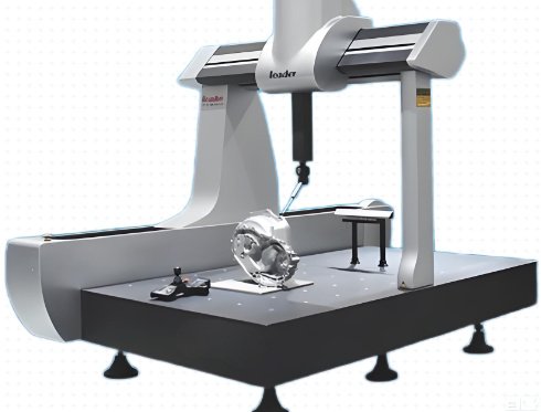
For higher accuracy or complex geometries, optical measurement systems, structured light scanners and coordinate measuring machines (CMM) can be used. These create point clouds or sampled points that can be compared to CAD models to evaluate dimensional deviations, warpage and profile errors. The practicality of such methods depends on prototype budget and criticality.
Measurement Techniques for CNC Machined Prototypes
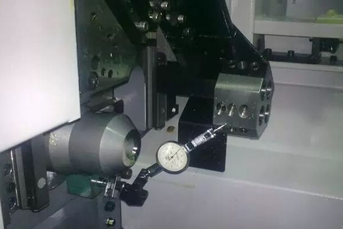
CNC machined parts typically have well-defined edges and smooth surfaces, which are suitable for traditional measurement tools. Vernier calipers, micrometers, height gauges and bore gauges are widely used for first article inspection and small batches.
For tighter tolerances or safety-critical features, CMM inspection with touch probes or scanning heads is employed. CMMs can check GD&T characteristics such as position, flatness and circularity with high repeatability. For turned components, roundness testers and surface roughness testers may be used to validate functional characteristics.
Design Considerations When Specifying Tolerances
Effective prototype tolerance specification involves balancing functionality, process capability and cost. Overly tight tolerances can cause delays and unnecessary expense, while loose tolerances may compromise fit and functional evaluation.
Choosing Tolerances for 3D Printed Prototypes
When designing for 3D printing, tolerances must account for layer resolution, orientation effects and post-processing. Common considerations include:
Allowances for fits: clearance between mating parts is often increased compared with machined components, especially for FDM. For snap fits, hinges or sliding features, empirical tuning based on prior builds is often more reliable than theoretical values alone. Feature size limits: small holes, thin walls and fine details have minimum reliable sizes depending on process and material. Designing too close to these limits can cause significant dimensional variation.
For critical interfaces with machined components, designers may choose to oversize or undersize certain features and then adjust them via drilling, tapping or light machining after printing.
Choosing Tolerances for CNC Machined Prototypes
In CNC machining, tolerances are often chosen relative to feature function and manufacturing complexity. For noncritical cosmetic features, default shop tolerances may be sufficient, while critical fits get tighter values.
Aspects to consider include:
Datum strategy: locating key functional features from a consistent datum system improves accuracy and reduces cumulative error. Avoiding unnecessary tight tolerances: specifying tight tolerances on every dimension increases programming and inspection effort without improving functionality. Allowances for finishing: anodizing, plating or coating will add or remove material, so nominal dimensions may be adjusted to achieve final functional dimensions.
Strategic tolerance selection helps keep prototype cost controlled while providing the necessary precision where it matters.
Combining 3D Printing and CNC Machining in Prototyping
Many prototype programs use both 3D printing and CNC machining. This combination leverages the speed and geometry freedom of 3D printing with the precision and surface finish of machining.
Hybrid Parts and Secondary Machining of Printed Components
Hybrid parts are those where a 3D printed blank or near-net shape is subsequently machined in selected areas. Typical applications include:
Machining reference surfaces and datums on a printed core. Reaming or boring printed holes to achieve accurate diameters and positions. Machining sealing faces, bearing seats or precision alignment features.
When planning hybrid production, additional material must be provided in the printed model for machining stock, and fixturing surfaces must be considered from the start. The transition between printed and machined surfaces should be controlled so that dimensional and surface quality requirements are met at the interface.
Assembly of Mixed-Process Components
In assemblies that mix 3D printed and CNC machined parts, tolerance stack-ups must reflect the different process capabilities. For example, a machined shaft may be designed with a tighter tolerance than a printed housing bore, while still achieving a functional fit.
Designers often choose to locate assemblies on machined components and allow printed parts to float slightly via compliant features, flexible seals or larger clearances. This approach allows functional testing and fit assessment without imposing unrealistic precision requirements on the printed parts.
Cost, Lead Time and Risk Considerations
While the focus is on tolerances, cost and lead time cannot be separated from tolerance decisions. Tight tolerances often require more machine time, manual finishing and detailed inspection.
Tolerance vs Cost Tradeoffs
For both 3D printing and CNC machining, several cost-related aspects are associated with tighter tolerances:
More precise process settings, which may increase scrap risk and require more operator time. Additional setups or fixtures to ensure datum alignment. Extended inspection, including CMM programs or optical scanning.
In prototype projects, it is common to begin with moderate tolerances and refine them in later iterations only if functional testing indicates a need for higher precision.
Lead Time and Iteration Speed
3D printing offers rapid turnaround for many geometries, enabling quick fit checks even when tolerances are moderate. CNC machining may have longer setup times, but for parts that require precise tolerances from the beginning, machining can reduce the number of iterations needed.
Choosing tolerances that are compatible with the intended process and project schedule reduces risk of delays due to rework or rejection. Communication with manufacturing partners about realistic tolerance capabilities at the prototype stage is often as important as the numeric values specified on the drawing.
Typical Tolerance-Driven Pain Points in Prototyping
Engineering teams frequently encounter specific issues related to tolerances when moving from CAD to physical prototypes. These can affect both 3D printing and CNC machining, but manifest differently due to process characteristics.
Fit and Assembly Issues
Common problems include interference fits when clearance fits were intended, loose fits due to process variation or overcompensation, and cumulative stack-up errors when multiple components are each within tolerance but the assembly exceeds functional limits.
Addressing these issues often involves revising tolerance schemes, adjusting nominal dimensions based on real data, or altering assembly methods to be more tolerant of variation.
Distortion and Warpage
In 3D printing, warpage of flat surfaces or long beams can cause parts to deviate from the intended shape, making them difficult to assemble or measure. In machining, thin walls and large flat panels may distort when unclamped from fixtures, changing the effective dimensions.
Mitigation strategies include redesigning parts with more uniform wall thickness, adding ribs or reliefs, or altering the process parameters and fixturing methods to reduce internal stress and deformation.
Inspection Uncertainty
Rough surfaces, small features and complex geometries can complicate measurement. Inconsistent inspection methods between design, manufacturing and quality teams can create disputes about whether parts meet specification.
Establishing clear measurement procedures, reference conditions and acceptable measurement tools for prototypes helps reduce ambiguity, especially when deciding whether deviations discovered in early builds are acceptable for subsequent design decisions.
Guidelines for Choosing Between 3D Printing and CNC Machining
When tolerance requirements are central to prototype performance, process selection should align with the required accuracy, surface quality and material behavior. The table below summarizes general guidance linking typical tolerance needs to suitable processes.
| Primary Requirement | Typical Tolerance Range | Recommended Process Orientation | Remarks |
|---|---|---|---|
| Concept models, early form factor checks | ±0.3–0.8 mm | 3D printing (FDM, SLA, SLS) | Focus on speed and cost; tolerances secondary |
| General assembly fit, moderate functional tests | ±0.15–0.3 mm | Higher-precision 3D printing (SLA, SLS, MJF) or basic CNC machining | Choose based on material and geometry complexity |
| Precision mechanical fit, bearing or seal interfaces | ±0.01–0.05 mm | CNC machining (milling and turning) | 3D printing may be used for noncritical components |
| Complex internal channels plus precise sealing surfaces | ±0.05–0.10 mm on critical faces | Metal 3D printing plus secondary CNC machining | Hybrid approach for functional prototypes |
| Clearance tests with flexible or snap-fit components | ±0.2–0.3 mm, tuned by testing | SLS, MJF or SLA with empirical design adjustments | Iterative builds often used to dial in fit |
These guidelines provide a starting point. Actual decisions should consider available equipment, supplier capabilities, project priorities and the potential value of faster iterations versus initial precision.
FAQ: Prototype Tolerances, 3D Printing and CNC Machining
How tight can tolerances realistically be for 3D printed prototypes?
For most commercial 3D printing services, realistic tolerances for prototypes fall in the ±0.05–0.30 mm range, depending on technology and part size. SLA and DLP can reach around ±0.05–0.15 mm on small features, while SLS and MJF are typically around ±0.10–0.25 mm or a small percentage of overall dimension. FDM is usually less precise, often ±0.15–0.30 mm or more. Achieving tighter tolerances than these values on 3D printed parts usually requires selective secondary machining of critical features.
When should I choose CNC machining over 3D printing for a prototype?
CNC machining is preferable when your prototype demands tight tolerances below roughly ±0.10–0.15 mm on critical features, very accurate hole positions, fine bearing or sealing fits, or when you must match the properties of production materials closely (for example, aluminum, steel or engineering plastics with specific mechanical or thermal performance). If the geometry is not excessively complex and lead time allows for machining setups, CNC machining typically delivers more consistent dimensional accuracy and surface finish than 3D printing.
Can I mix 3D printed and CNC machined parts in the same prototype assembly?
Yes, combining 3D printed and CNC machined components is common and often effective. Machined parts can provide precision datums, shafts, bearing seats and sealing faces, while 3D printed parts can supply complex housings, covers and internal structures. To make this work, define the assembly’s functional datums primarily on the machined parts and allow larger tolerances on printed elements. In some cases, a 3D printed part may be used as a near-net blank with key surfaces and holes machined afterwards to align tolerances with the rest of the assembly.
How should I specify tolerances for prototype parts if I am not sure about final production methods?
A practical approach is to specify functional tolerances only where necessary and keep other dimensions at reasonable general tolerances aligned with the chosen prototype process. Use GD&T to control critical relationships such as mating faces, hole locations and alignment features, but avoid over-constraining noncritical dimensions. After receiving initial prototypes, use measurement data and functional tests to refine tolerances for later iterations and for eventual production drawings, adjusting them to suit the intended production process once it is defined.
Do surface finishes change the effective tolerances on prototypes?
Surface finish affects how parts contact each other and can effectively tighten or loosen functional fits. For example, rough as-printed surfaces can cause interference even when nominal dimensions suggest clearance, while aggressive sanding, bead blasting or polishing can remove enough material to shift critical dimensions outside tolerance. For machined parts, finishing treatments such as anodizing or plating change dimensions by adding or removing microns of material. When specifying tolerances for prototypes, include finishing operations in your nominal values and consider how roughness or coatings may alter the effective fit.
