
3-axis CNC machining is one of the most widely used subtractive manufacturing processes for producing precise metal and plastic components. By moving a cutting tool along the X, Y, and Z axes, it can create flat surfaces, slots, pockets, and simple 3D features with high dimensional accuracy and repeatability. This article explains the technical capabilities, suitable materials, achievable tolerances, geometric limitations, and practical design considerations of 3-axis CNC machining for engineering and sourcing professionals.
Fundamentals of 3-Axis CNC Machining
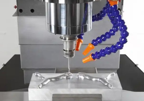
3-axis CNC machining refers to material removal operations performed by computer numerical control equipment where the tool or workpiece moves along three orthogonal axes: X (left-right), Y (front-back), and Z (up-down). It is the baseline configuration for CNC milling and certain CNC routing applications.
In typical 3-axis milling, the workpiece is fixed on a stationary table and the spindle, holding the cutting tool, moves in three linear directions to reach the required coordinates. The control system interprets G-code commands generated from CAD/CAM software to execute toolpaths that form the desired geometry.
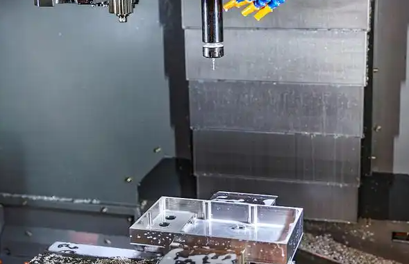
3-axis machining is best suited to prismatic parts, planar features, and moderately contoured surfaces that are accessible from one side or from multiple sides through re-clamping and re-orientation. For many industrial parts, it offers an optimal balance of productivity, accuracy, and cost.
Core Capabilities of 3-Axis CNC Machining
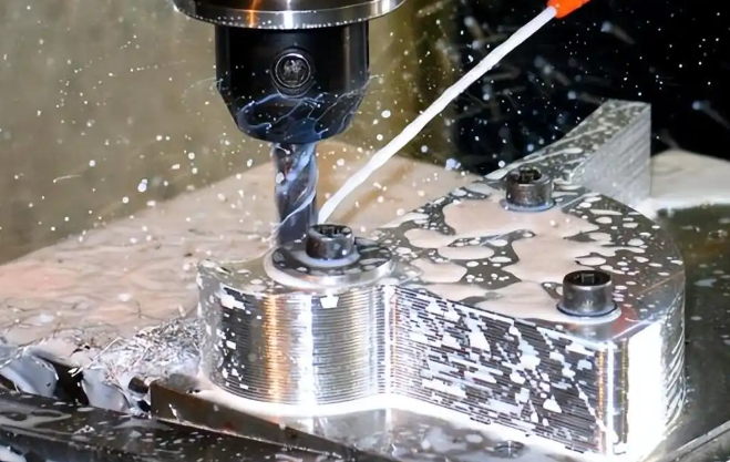
3-axis CNC machines support a wide set of operations and part features. Understanding these capabilities helps engineers allocate the right geometries and tolerances to this process.
Basic Machining Operations
- Face milling and surfacing of flat planes.
- Peripheral milling of external profiles and shapes.
- Slotting and pocketing with end mills and slot drills.
- Drilling, counterboring, countersinking, and tapping with appropriate tooling.
- Boring and reaming for improved hole accuracy and surface finish.
- Chamfering and deburring of edges.
These operations can be combined in a single setup or across multiple setups for parts requiring access from different directions.
Typical Geometries and Features
3-axis machining can produce a broad variety of geometric features, such as:
- 2D profiles: brackets, plates, frames, adapter plates, simple housings.
- 3D pockets and cavities: shallow or moderately deep pockets with filleted corners, bosses, and islands.
- Planar and stepped surfaces: steps, ledges, and tiered surfaces at various heights.
- Holes and patterns: bolt circles, hole grids, precision dowel holes, threaded holes.
- Engraving and shallow 3D reliefs: text, logos, and light contours on flat surfaces.
When multiple setups are used, it is possible to machine several sides of a part by reorienting the workpiece in vises or fixtures, as long as each surface can be accessed from a direction normal (or nearly normal) to that surface by a vertical or horizontal spindle.
Machine Travel and Work Envelope
The maximum part size in 3-axis CNC machining is constrained by the machine’s travel range and table size. Industrial 3-axis mills are available in many sizes, from small benchtop machines to large bed mills and gantry systems. Typical ranges include:
- Small vertical machining centers: approximate travels of 400–800 mm (X) × 300–500 mm (Y) × 300–500 mm (Z).
- Medium vertical machining centers: approximate travels of 800–1500 mm (X) × 500–800 mm (Y) × 500–800 mm (Z).
- Large bed or gantry mills: travels can exceed 2000 mm in X and 1000 mm in Y, with Z travel depending on design.
Effective workpiece size is usually slightly smaller than the full travel envelope to allow for workholding and tool clearance.
Dimensional Tolerances in 3-Axis CNC Machining
Dimensional tolerance is a key performance parameter for any machining process. In 3-axis CNC machining, attainable tolerances depend on the machine configuration, tooling, workholding, material, part geometry, and environmental conditions such as thermal stability.
General Tolerance Ranges
Commercial 3-axis CNC machining can typically achieve the following order-of-magnitude tolerances without special processes:
- Standard dimensional tolerance: ±0.05 mm to ±0.1 mm (±0.002 in to ±0.004 in) on most dimensions.
- Tight tolerance capability: ±0.01 mm to ±0.02 mm (±0.0004 in to ±0.0008 in) on critical features, with appropriate process control.
- Hole diameters: ±0.02 mm or better with finishing operations such as reaming or boring.
- Flatness and parallelism: often within 0.02–0.05 mm over 100 mm, depending on setup and material.
These values represent typical industrial practice for 3-axis machines in good condition. Actual tolerances should be agreed upon with the machining supplier for each project based on part size, material, and feature type.
Factors Affecting Tolerance Achievement
Several technical factors influence the ability to hold tight tolerances in 3-axis CNC machining:
- Machine rigidity and accuracy: high-quality linear guides, ball screws, and encoders provide more stable positioning.
- Workholding: rigid, repeatable clamping systems reduce deflection and movement under cutting forces.
- Tooling: tool length, tool diameter, tool wear, and runout all affect dimensional accuracy, particularly in deep pockets or fine features.
- Material properties: hardness, machinability, thermal expansion, and internal stress influence size stability.
- Cutting parameters: feed rate, spindle speed, step-over, and depth of cut must be tuned to minimize deflection and vibration.
- Thermal conditions: temperature changes during long machining cycles or between roughing and finishing operations can cause dimensional drift.
For tight tolerances on critical features, it is common to rough the part, allow it to relax, and then perform finishing passes with small depths of cut and stabilized conditions.
Recommended Tolerance Practices
To balance manufacturability and quality in 3-axis CNC machining:
- Specify standard tolerances (e.g., ±0.1 mm) for non-critical features to reduce machining time and cost.
- Limit the number of dimensions requiring tight tolerances (e.g., ±0.01 mm) to those that directly affect fit and function.
- Use geometric dimensioning and tolerancing (GD&T) for clear control of features such as datums, position, concentricity, flatness, and perpendicularity.
- Match tolerance bands to part size; extremely tight tolerances over large spans are difficult and expensive to achieve.
Surface Finish and Accuracy
Surface finish influences part performance, aesthetics, and functional properties such as friction, sealing, and fatigue resistance. 3-axis machining can achieve a broad range of surface finishes depending on toolpaths, tooling, and cutting conditions.
Typical Machined Surface Roughness
Common ranges of arithmetic average roughness (Ra) for 3-axis CNC machining are as follows:
| Operation | Typical Ra (µm) | Typical Ra (µin) | Notes |
|---|---|---|---|
| Rough milling | 3.2 – 6.3 | 125 – 250 | High material removal, visible tool marks |
| Semi-finish milling | 1.6 – 3.2 | 63 – 125 | Reduced step-over and feed |
| Finish milling | 0.8 – 1.6 | 32 – 63 | Fine step-over, sharp tools |
| High-quality finish passes | 0.4 – 0.8 | 16 – 32 | Optimized parameters, small tools |
| Reamed or bored holes | 0.4 – 1.6 | 16 – 63 | Smooth internal surfaces |
Surface roughness is influenced by feed per tooth, step-over, tool geometry, tool wear, and machine vibration. For critical sealing surfaces or aesthetic components requiring smoother finishes, post-processing such as grinding, polishing, or lapping may be applied after 3-axis machining.
Form Accuracy and Geometric Features
Beyond linear dimensions, 3-axis machining controls form and geometric accuracy, including:
- Flatness of faces, controlled by tool deflection, cutter path, and machine alignment.
- Parallelism between faces, determined by setup accuracy and fixture design.
- Perpendicularity between faces and features, dependent on squareness of machine axes and fixturing.
- Hole position accuracy, influenced by drilling strategy, peck cycles, and tool runout.
Using probing cycles and in-process measurement can improve geometric control, particularly for parts requiring tight relationships between multiple features.
Materials for 3-Axis CNC Machining
3-axis CNC machining is compatible with a wide range of engineering materials. Material selection affects machinability, achievable tolerances, surface finish, part performance, and cost.
Aluminum Alloys
Aluminum is one of the most frequently machined materials due to its favorable combination of low density, good machinability, and corrosion resistance. Common grades include:
- Aluminum 6061: widely used, good strength-to-weight ratio, excellent machinability, suitable for general-purpose structural components, brackets, housings, and fixtures.
- Aluminum 6082, 6063: used in structural profiles and extrusions, also machinable for components needing improved mechanical properties.
- Aluminum 7075: high-strength alloy for aerospace and performance-critical parts; machinable but more demanding than 6061, often used where high strength and low weight are required.
- Aluminum 2024: high strength and fatigue resistance, frequently used in aerospace structures and mechanical components.
Aluminum allows relatively aggressive cutting parameters and provides good surface finishes with appropriate tooling. Dimensional stability is generally good, though thin-walled sections may require careful machining strategies.
Steel and Stainless Steel
Various steels are machined with 3-axis CNC equipment for structural, tooling, and mechanical components:
- Mild steels (e.g., 1018, 1020): good machinability, commonly used for general mechanical parts, shafts, and fixtures.
- Alloy steels (e.g., 4140, 4340): higher strength and toughness, used in gears, shafts, and structural parts; machining can be more demanding, especially in hardened conditions.
- Tool steels (e.g., D2, A2, O1): used for dies, molds, and wear-resistant parts; often machined in annealed state and then heat-treated.
- Stainless steels (e.g., 304, 316, 17-4 PH): corrosion-resistant alloys for medical, food processing, marine, and chemical applications; some grades exhibit work hardening, requiring optimized cutting conditions and tooling.
For steels, choosing suitable cutting tools (e.g., coated carbide, high-speed steel for specific conditions) and controlling heat buildup are essential to maintain surface quality and tool life.
Copper, Brass, and Other Non-Ferrous Metals
Copper and copper alloys are machined for electrical and thermal components:
- Copper: excellent thermal and electrical conductivity; relatively soft and sticky, requiring sharp tools and controlled chip evacuation.
- Brass (e.g., C360): very good machinability, producing clean chips and fine finishes, widely used for fittings, valves, and decorative elements.
- Bronze: used for bushings, bearings, and marine components, with machinability varying based on alloy composition.
These materials often achieve fine surface finishes and tight tolerances with well-tuned machining conditions.
Plastics and Polymers
Many engineering plastics are well suited for 3-axis CNC machining, including:
- ABS and polycarbonate: used for housings, covers, and functional prototypes; require careful fixturing due to lower stiffness.
- POM (acetal, Delrin): excellent machinability, low friction, used for gears, bushings, and precision components.
- Nylon (PA): good wear properties, used for mechanical parts; can absorb moisture, which may affect dimensions.
- PEEK: high-performance thermoplastic with excellent chemical and temperature resistance; requires optimized tooling due to its toughness.
- PTFE (Teflon): low friction and chemical resistance, soft and prone to deformation, requiring gentle cutting and careful clamping.
Plastics typically require lower cutting forces but are more susceptible to thermal expansion, warping, and deformation. Generous clamping support, moderate cutting parameters, and consideration of residual stresses are recommended.
3-Axis CNC Machining vs Other CNC Configurations
While 3-axis machines are widely used, other configurations such as 4-axis and 5-axis machines provide additional motion capabilities. Understanding the differences helps determine when 3-axis machining is technically adequate.
Comparison of Axis Capabilities
| Configuration | Axes of Motion | Typical Use Cases | Key Characteristics |
|---|---|---|---|
| 3-axis | X, Y, Z linear | Prismatic parts, flat surfaces, pockets, simple 3D contours | Common, cost-effective, requires multiple setups for multi-side machining |
| 4-axis | X, Y, Z + rotary (A or B) | Parts with features around a cylinder, radial patterns, indexing operations | Improved accessibility for side features, less manual re-clamping |
| 5-axis | X, Y, Z + two rotary (A/B/C) | Complex free-form surfaces, impellers, multi-side features in one setup | Enhanced accessibility, reduced setups, suitable for complex geometries |
3-axis machining remains the primary choice for a large share of industrial parts where features are accessible from a limited number of orientations and do not require continuous multi-axis tool orientation.
Geometric Limitations and Design Considerations
Because the cutting tool in 3-axis machines is restricted to linear movements along X, Y, and Z, part design must account for accessibility and tool geometry. This section outlines significant geometric constraints.
Tool Access and Reachability
In 3-axis machining, the tool typically approaches the workpiece from a single direction per setup. For vertical machining centers, this direction is along the Z-axis. Consequently:
- Features must be visible to the tool from the machining direction without obstruction.
- Undercuts and features hidden behind walls cannot be machined unless specialized tools or additional setups are used.
- Deep cavities are limited by tool length and stiffness, as excessive length leads to deflection and chatter.
Multi-side parts can be machined by reorienting the part in different setups (e.g., machining top, then sides, then bottom), but each setup adds complexity and can affect positional accuracy between features.
Minimum Feature Sizes and Tool Diameters
Minimum feature size in 3-axis machining is largely governed by the smallest practical tool diameter and its length. General guidelines include:
- Minimum slot or internal radius: typically no smaller than 1.0 mm tool diameter for general work; smaller tools are feasible but more fragile and slower.
- Minimum wall thickness (metals): commonly 0.5–1.0 mm for short walls; thicker walls are recommended for tall or unsupported sections.
- Minimum wall thickness (plastics): often 1.0–2.0 mm to reduce warping and deflection during machining.
- Lettering and engraving: line widths about 0.3–0.5 mm are typical, depending on material and tooling.
Using unnecessarily small features increases machining time and risk of tool breakage. Designers should balance functional requirements against machining practicality.
Depth-to-Width Ratios
Deep slots and pockets are limited by tool rigidity and chip evacuation. Common practice is to limit:
- End mill depth of cut to around 3–5 times the tool diameter for efficient machining.
- Very deep cavities to multiple step-down passes with intermediate clearing to avoid chip packing.
When deeper features are mandatory, combining roughing with a larger tool and finishing with a smaller tool can improve accuracy while managing deflection.
Corner Radii and Internal Fillets
Because milling tools are rotary, internal corners will always have a radius. Designing with realistic internal radii facilitates machining:
- Prefer internal corner radii equal to or larger than the cutter radius (e.g., at least 1 mm for a 2 mm diameter cutter).
- Larger radii such as 3 mm or 5 mm are easier to machine and reduce tool wear.
- Sharp internal corners require secondary operations (e.g., EDM or broaching) and should be specified only where functionally necessary.
Generous radii also help reduce stress concentrations in the finished part.
Workholding and Fixturing for 3-Axis CNC
Secure and repeatable workholding is essential for accuracy, productivity, and safety in 3-axis CNC machining. The choice of workholding method depends on part geometry, material, and production volume.
Common Workholding Methods
- Machine vises: versatile for prismatic parts with parallel faces; often used with soft jaws customized to part geometry.
- Clamping on T-slot tables: clamps, step blocks, and toe clamps are suitable for plates and large parts.
- Fixture plates: plates with grid holes and dowel pins allow repeatable setups and easy repositioning.
- Dedicated fixtures: custom fixtures designed for specific parts, particularly for high-volume or complex multi-side machining.
- Vacuum fixtures: used for thin plates or panels where mechanical clamping would cause distortion.
Correct workholding minimizes part movement under cutting loads and provides clear access for the tool, while avoiding interference with the spindle or tool holder.
Influence of Workholding on Tolerances
Workholding impacts both dimensional and geometric tolerances:
- Insufficient clamping leads to micro-movements and inconsistent dimensions.
- Excessive clamping force on thin or plastic parts can cause deformation, resulting in out-of-tolerance features when unclamped.
- Multi-side machining requires careful datum selection and repeatable locating surfaces to maintain positional accuracy between setups.
It is good practice to define datums that correspond to stable, easily accessible surfaces and to align them with part features critical to assembly and function.
Tooling, Cutting Parameters, and Process Stability
Tool selection and cutting parameters significantly affect machining performance, surface quality, and tool life in 3-axis CNC machining.
Tool Types and Materials
Common tools used in 3-axis machining include:
- End mills (flat, ball, and corner radius) for profiling, slotting, and pocketing.
- Face mills for surfacing large flat areas.
- Drills (twist drills, center drills) for hole creation.
- Reamers and boring tools for precision hole finishing.
- Taps and thread mills for internal threads.
Tool materials range from high-speed steel (HSS) for softer materials and lower-speed applications to solid carbide for higher speeds and greater wear resistance. Coatings such as TiN, TiAlN, or DLC can enhance tool life, particularly when machining abrasive or hard materials.
Cutting Parameters
Key cutting parameters in 3-axis machining include:
- Spindle speed (rpm): determines cutting speed at the tool edge; must be matched to material and tool diameter.
- Feed rate (mm/min or in/min): influences chip load and surface finish; excessive feed can lead to poor finish and tool breakage.
- Depth of cut and step-over: affect material removal rate and tool load; roughing uses larger values, finishing uses smaller values for better accuracy.
Stable machining requires balancing these parameters with tool rigidity, workholding strength, and machine capabilities. Process optimization often involves iterative adjustment of parameters to achieve a combination of productivity and part quality.
Applications and Use Cases of 3-Axis CNC Machining
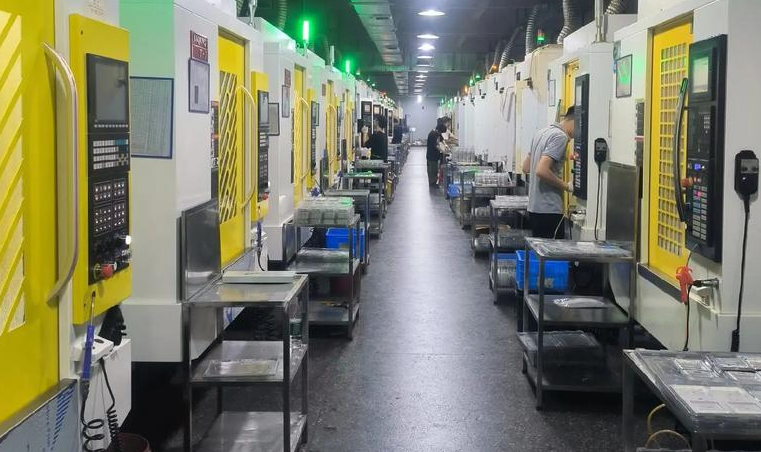
3-axis CNC machining is applied across many industries for production, tooling, and prototyping. Its capabilities align well with a wide variety of mechanical components.
Industrial Components and Machinery
Common applications include:
- Machine brackets, frames, and mounting plates.
- Mechanical housings and enclosures with planar faces and pockets.
- Fixtures and jigs for assembly, testing, and inspection.
- Shafts, flanges, and adapter plates produced via milling from solid stock.
In these applications, 3-axis machining provides reliable dimensional accuracy, robust surface finishes, and reasonable cycle times.
Aerospace, Automotive, and Electronics
In aerospace and automotive fields, 3-axis machining is used for:
- Structural aluminum brackets and supports.
- Engine and drivetrain components with primarily prismatic features.
- Tooling and fixtures for composite layup and assembly.
In electronics and instrumentation, 3-axis machining produces:
- Precision aluminum or plastic housings.
- Heatsinks and cooling plates.
- Connector blocks and mounting interfaces.
These parts benefit from the combination of precise features, good surface quality, and the ability to machine from solid billets or plate stock.
Prototyping and Low-Volume Production
3-axis CNC machining is widely used for functional prototypes and low to medium production volumes:
- Rapid production of metal or plastic prototypes with mechanical properties close to final parts.
- Bridge production while tooling for other processes (e.g., casting, molding) is being developed.
- Custom or low-volume parts that are not economically viable for high-tooling-cost processes.
The digital nature of CNC machining allows easy iteration: design changes can be implemented by updating the CAD/CAM programs without physical tooling modifications.
Pain Points and Limitations of 3-Axis CNC Machining
Despite its versatility, 3-axis machining has inherent constraints that users should consider when designing parts or planning production.
Limited Access to Complex Geometries
Because the tool approaches from a single direction per setup, 3-axis machining struggles with:
- Internal undercuts and back-side features that cannot be reached from a straight tool path.
- Complex free-form surfaces requiring continuous tool orientation changes.
- Deep cavities with internal features that cannot be reached by standard tools without excessive tool length.
Such geometries may require multiple setups, special tooling, or alternative manufacturing methods.
Multiple Setups and Alignment
When a part needs machining on several faces, multiple setups are required. This introduces:
- Additional time for re-clamping and re-aligning each setup.
- Potential accumulation of positional errors between interfaces.
- Increased complexity in process planning and fixture design.
For some components, this makes 3-axis machining less efficient than processes that can complete more operations in a single setup.
Constraints on Very Tight Tolerances Over Large Spans
Holding extremely tight tolerances across large dimensions can be challenging due to:
- Thermal expansion of workpiece and machine components.
- Slight deviations in machine geometry over long travels.
- Cumulative errors from multiple tool changes and setups.
In such cases, achieving specified tolerances may require additional process control, environment stabilization, or post-machining operations such as grinding.
Practical Design Guidelines for 3-Axis CNC Machining
To obtain reliable, cost-effective parts from 3-axis machining, designers can follow a set of practical rules tailored to the process capabilities.
Optimize Part Geometry for Machining
Guidelines include:
- Align major faces and features with standard Cartesian planes (X, Y, Z) to simplify setups and toolpaths.
- Use consistent wall thicknesses where possible to reduce distortion and uneven cooling effects.
- Provide adequate radii in internal corners and avoid unnecessary sharp internal features.
- Limit extremely thin fins or tall slender structures that are prone to vibration and deflection.
Use Appropriate Tolerances and Surface Requirements
Careful specification of tolerances and finishes helps control costs and lead times:
- Apply general tolerances for non-critical features and reserve tight tolerances for functional interfaces.
- Avoid specifying overly fine surface finishes on non-functional surfaces.
- Indicate critical datums clearly so machining and inspection can prioritize these features.
Consider Material Behavior
Material selection should account for machining behavior and in-service performance:
- Choose materials with good machinability when possible, especially for prototypes and moderate loads.
- Account for thermal expansion, moisture absorption, and residual stress for plastics and certain alloys.
- Include allowances for heat treatment or finishing processes that might follow machining.
Plan for Workholding and Setups
During design, consider how the part will be clamped and oriented:
- Include flat reference surfaces and clamping areas that do not interfere with functional features.
- Avoid designs that require clamping on delicate functional surfaces whenever possible.
- For multi-side parts, consider features that can serve as repeatable locating surfaces between setups.
FAQ About 3-Axis CNC Machining
What is 3-axis CNC machining?
3-axis CNC machining is a computer-controlled manufacturing process where a cutting tool moves along three axes—X, Y, and Z—to shape a part from a solid material.
How does 3-axis machining compare with 5-axis machining?
3-axis machines move the tool in three linear directions only, while 5-axis machines also rotate around two additional axes, allowing machining of complex shapes and angled features in a single setup.
When is 3-axis CNC machining sufficient instead of 5-axis?
CNC machining is sufficient when most features</a> are accessible from one or a few primary directions and do not require continuous tool orientation changes. Typical examples include prismatic parts, plates with pockets and holes, housings with features on a limited number of faces, brackets, and many types of fixtures. If the geometry can be reached through a manageable number of setups and does not include complex undercuts or intricate free-form surfaces, 3-axis machining usually provides a cost-effective and accurate solution.
What types of features can a 3-axis CNC machine create?
A 3-axis CNC machine can produce flat surfaces, slots, pockets, holes, threads, and simple 3D contours. It is ideal for prismatic parts and moderately complex geometries, but features requiring angled cuts or undercuts may need a 4-axis or 5-axis machine.
