
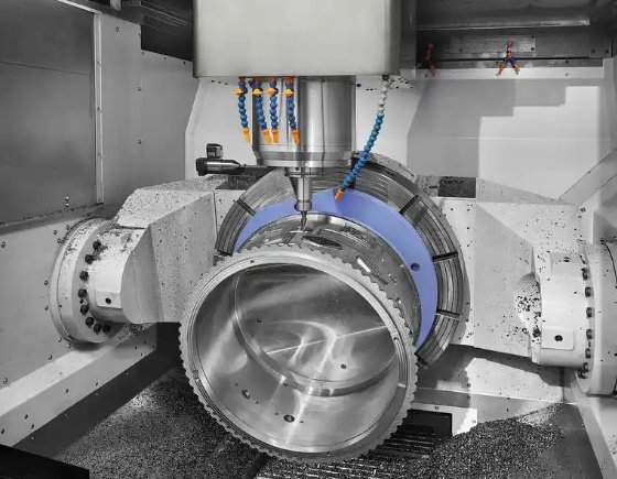
Definition and Basic Concepts of 5-Axis Machining
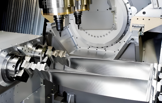
5-axis machining is a form of computer numerical control (CNC) machining in which the cutting tool or the workpiece can be moved along five different axes simultaneously or in a coordinated manner. Traditional 3-axis machining uses X, Y, and Z linear axes. 5-axis machining adds two rotary axes, allowing more complex tool orientations and access to multiple sides of a part in a single setup.
In a typical 5-axis milling configuration, the three linear axes are:
- X-axis: horizontal movement, usually left-right
- Y-axis: horizontal movement, usually front-back
- Z-axis: vertical movement, up-down
The two additional rotary axes can be implemented in different ways depending on the machine design. By controlling all five axes, the machine can position the tool at almost any angle relative to the workpiece, allowing efficient machining of complex free-form surfaces, undercuts, and features on multiple faces.
5-axis machining is widely used in industries that require tight tolerances and complex geometries, such as aerospace, medical devices, energy, automotive performance components, and high-end molds and dies.
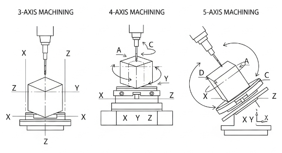
5-Axis Versus 3-Axis and 4-Axis Machining
To understand 5-axis machining clearly, it is useful to compare it with 3-axis and 4-axis machining.
In 3-axis machining, the cutting tool moves only in X, Y, and Z. The tool always approaches the part from a direction parallel to the Z-axis. When different sides of a part must be machined, the workpiece is manually re-clamped in new orientations, which adds time and introduces errors due to re-fixturing.
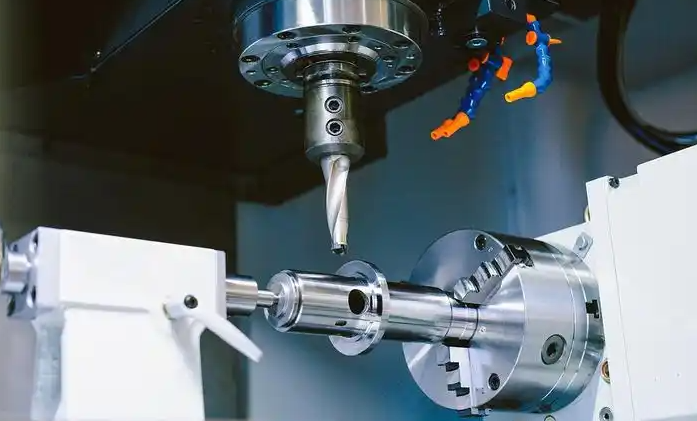
In 4-axis machining, one rotary axis is added, usually a rotation around the X-axis (A-axis) or around the Z-axis (C-axis). This allows indexing the part to machine around a single rotational axis, which helps with features such as radial holes or simple cylindrical parts that require operations at multiple angles around one axis.
5-axis CNC machining goes further by adding two rotary axes. This enables the tool or the part to be oriented dynamically to keep the tool normal or near normal to the surface being machined. It reduces the need for multiple setups and improves access to complex surfaces and internal features.
Key differences include:
- Tool orientation: 3-axis lacks variable orientation, 5-axis can continuously tilt the tool.
- Setup count: 5-axis can significantly reduce the number of setups required.
- Surface quality: 5-axis can maintain a more favorable cutting angle and consistent step-over on complex surfaces.
- Feature accessibility: 5-axis can reach undercuts and compound-angle features more effectively.
Axes, Rotary Configurations, and Kinematics
5-axis machines can be designed in multiple kinematic configurations. The linear axes are X, Y, and Z. The two rotary axes are commonly denoted as A, B, and C, where:
- A-axis: rotation around X-axis
- B-axis: rotation around Y-axis
- C-axis: rotation around Z-axis
A particular machine will implement two of these rotary axes. The geometric arrangement of these rotary axes with respect to the linear axes defines the kinematics of the machine. Kinematics directly influences reachable angles, collision risk, machining accuracy, and how the CAM system must post-process toolpaths.
| Configuration Type | Rotary Axes Placement | Typical Axis Combination | Main Characteristics |
|---|---|---|---|
| Table-Table (Trunnion) | Both rotary axes under the workpiece | A-axis (tilting) + C-axis (rotary table) | Rigid setup, good for heavy metal removal, common in mold and aerospace part machining |
| Table-Head | One rotary in the table, one in the spindle head | C-axis in table + B-axis in head | Balanced capabilities, suitable for general 5-axis work with medium-sized parts |
| Head-Head | Both rotary axes in the spindle head | A-axis + C-axis or B-axis + C-axis in head | Workpiece remains stationary, beneficial for large or heavy parts such as structural components |
| Swivel-Rotary Table | Tilting table and rotary axis combined | B-axis tilting table + C-axis rotary | Compact footprint, flexible orientation control with direct workpiece tilting |
| Gantry 5-Axis | Rotary axes in head, large bridge structure | B-axis head + C-axis head (varies) | Used for very large parts such as aircraft skins and molds with large travel ranges |
Depending on the kinematic layout, the machine may have different limits on rotary motion. For example, a tilting A-axis might have travel from -110° to +110°, while a C-axis might offer 360° continuous rotation. These limits define the maximum orientation angles that can be used in a toolpath and must be considered during CAM programming and setup.
Types of 5-Axis Machining: Simultaneous and 3+2
5-axis machining is generally categorized into two main modes of operation: simultaneous 5-axis and 3+2 (also called positional 5-axis).
Simultaneous 5-Axis Machining
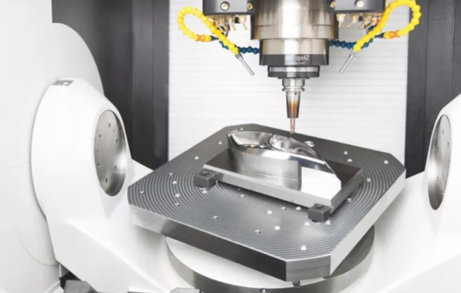
In simultaneous 5-axis machining, all five axes can move at the same time in a coordinated way while cutting. The orientation of the tool changes continuously as it follows the surface of the part. This mode is used for highly complex surfaces or features where the optimal tool orientation changes continuously along the toolpath.
Characteristics of simultaneous 5-axis machining include:
- Continuous tool tilting: Tool angle changes along the path to maintain favorable cutting conditions.
- Shorter tools: By tilting the tool, shorter tool lengths can be used, which increases stiffness and reduces vibration.
- Smoother surfaces: More consistent surface finish on complex free-form geometries.
- Reduced cycle time: Efficient toolpaths for multi-surface machining.
Simultaneous 5-axis requires advanced CAM software, a capable CNC control with high-speed 5-axis interpolation, and careful programming to avoid collisions and singularities in the motion.
3+2 (Positional) 5-Axis Machining
In 3+2 machining, the two rotary axes are used to index the part or tool to a fixed orientation, and then the machining operation is carried out using standard 3-axis motion. The rotary axes are not moving simultaneously with the linear axes during cutting; they move to a position and then lock while X, Y, and Z perform the cutting.
Typical 3+2 workflows include:
- Indexing to multiple angles to reach different faces of a part without manual re-clamping.
- Using angled orientations to maintain shorter tool overhang and better rigidity.
- Accessing holes and pockets at compound angles in one clamping.
3+2 machining provides many benefits of 5-axis machining (reduced setups, better tool access, improved rigidity) with simpler programming than full simultaneous 5-axis. It is often a first step for shops transitioning from 3-axis to 5-axis technology.
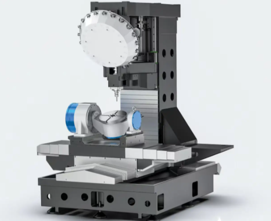
Key Components of a 5-Axis CNC Machine
A 5-axis CNC machine consists of mechanical, electronic, and software elements that work together to position and move cutting tools accurately. Understanding these components helps in machine selection, operation, and maintenance.
Mechanical Structure
The mechanical structure includes the frame, slides, tables, spindle head, and rotary units. Common structural forms are:
- Bridge or gantry frames for large-format machines with high rigidity.
- C-type frames for general-purpose vertical machining centers.
- Trunnion tables and swivel heads for compact 5-axis milling centers.
Important mechanical parameters include:
- Linear axis travel ranges (e.g., X: 800 mm, Y: 600 mm, Z: 600 mm).
- Rotary axis rotation ranges (e.g., A: -120° to +30°, C: 360° continuous).
- Maximum feed rates and rapids for both linear and rotary axes.
- Spindle power and torque ratings (e.g., 15 kW, 120 Nm).
- Spindle speed range (e.g., 50 to 18,000 rpm) and taper type (e.g., HSK, BT, CAT).
Rotary Axes and Tables
The additional rotary axes are implemented via rotary tables, tilting tables, rotary trunnions, or swiveling heads. Key parameters include:
- Bearing type and diameter, affecting rigidity and load capacity.
- Clamping torque, defining how securely the axis can lock during heavy cutting.
- Positioning accuracy and repeatability (often in arc-seconds).
- Maximum rotational speed (degrees per second or rpm).
High-quality rotary axes minimize backlash and maintain precise positioning under cutting loads. Direct-drive rotary motors and high-resolution encoders are often used for improved accuracy.
Spindle System
The spindle provides the rotation for the cutting tool. Important parameters:
- Speed range: Determines suitability for materials from aluminum (high speed) to titanium (lower speed, high torque).
- Power and torque curves: Indicate how much cutting force can be applied at various speeds.
- Taper interface: HSK, BT, and CAT are common systems, each with different stiffness and tooling options.
- Bearing configuration: Influences thermal stability and vibration characteristics.
For 5-axis machining of complex surfaces, spindle performance affects achievable surface finish, tool life, and cycle time.
CNC Control and Drives
The CNC control executes the part program and coordinates motion across all axes. Drives convert control signals into motion through motors. For 5-axis machining, the control must support:
- 5-axis interpolation: Coordinated motion of five axes, often with look-ahead and spline interpolation.
- Kinematic transformations: Mathematical mapping between programmed toolpaths and machine axes.
- Tool center point control: Keeping the tool tip at the programmed position while changing tool orientation.
- High-speed machining functions: Jerk control, acceleration optimization, and smoothing of small segments.
Servo motors and high-resolution encoders allow precise position feedback and control. The integration of control, drives, and mechanical elements determines dynamic performance and accuracy.
Tooling, Tool Holders, and Probing
Tooling for 5-axis machining includes a variety of cutters (ball-end mills, barrel cutters, bull-nose end mills, drills, reamers) and tool holders designed for high-speed, tilted engagement. Important aspects are:
- Runout: Small radial runout improves surface quality and tool life.
- Balance: Properly balanced tool assemblies minimize vibration at high rpm.
- Length and gauge control: Shorter tools improve rigidity; consistent lengths simplify programming.
Probing systems (spindle probes, tool setters) are often integrated to measure workpiece position, check features, and automate setup adjustments. This contributes to process reliability, especially in multi-axis machining where manual measurement can be difficult.
How 5-Axis Machining Works in Practice
The operating sequence of 5-axis machining includes design, planning, setup, programming, machining, and inspection. Each step requires careful attention to ensure part quality and process efficiency.
CAD Design and Model Preparation
The process begins with a 3D CAD model of the part. The model should be complete, with clearly defined surfaces, radii, holes, and toleranced features. For 5-axis machining, attention is given to:
- Surface continuity and quality: Avoid gaps and overlaps that can complicate toolpaths.
- Accessibility: Confirm that all features can be approached by a tool given machine limits.
- Stock definition: Accurately define raw material shape and size.
CAM Programming for 5 Axes
CAM (Computer-Aided Manufacturing) software is used to generate toolpaths suitable for 5-axis motion. The programmer selects operations, tools, and strategies based on material, part geometry, and machine capabilities. Typical 5-axis operations include:
- 3D surface finishing with ball or barrel mills using tilt control.
- Swarf cutting, where the side of the tool machines along a surface, maintaining constant contact.
- Multi-axis contouring along edges or blades.
- 5-axis drilling and hole machining at compound angles.
Key CAM parameters for 5-axis programming:
- Tool axis control: Limits for tilt and swivel, lead and lag angles, and collision avoidance rules.
- Step-over and step-down: Values that balance surface quality and cycle time.
- Feed rates: Adjusted for changing engagement as tool angle varies.
- Machine limits: Axis travel and rotary limits to prevent singularities.
The CAM system uses a post-processor to convert generic toolpaths into machine-specific G-code with the correct kinematics and control syntax.
Setup, Workholding, and Alignment
Workholding is critical in 5-axis machining because the workpiece may be oriented at multiple angles. Common workholding approaches include:
- 5-axis vises with low-profile jaws to improve access.
- Modular fixturing plates and risers to elevate the workpiece.
- Custom fixtures designed specifically for complex parts.
Important considerations:
- Clearance: Ensure the workpiece, fixture, and tool holder do not collide at extreme tilt angles.
- Reference points: Use precise datums that can be probed and aligned with the machine coordinate system.
- Clamping rigidity: Maintain sufficient clamping force while ensuring the fixture does not obstruct tool access.
Initial setup often includes probing cycles to locate the part, confirm orientation, and adjust the work coordinate system automatically.
Machining, Monitoring, and Finishing
During machining, the CNC control executes the 5-axis program, coordinating movements to maintain the desired tool orientation and path. Operators typically monitor:
- Load on the spindle and axes using current and torque readings.
- Vibration or chatter, especially with long tools or difficult materials.
- Coolant flow and chip evacuation, which may be affected by changing orientations.
After machining, finishing processes such as deburring, polishing, and inspection are performed. In some cases, 5-axis toolpaths can minimize manual finishing by achieving a finer surface finish on complex contours.
Capabilities and Advantages of 5-Axis Machining
5-axis machining provides a range of capabilities beyond traditional machining methods. These capabilities translate into practical advantages in precision, throughput, and component design freedom.
Complex Geometry and Free-Form Surfaces
5-axis machines excel at parts with free-form surfaces, deep pockets, sculpted features, and compound angles. Examples include:
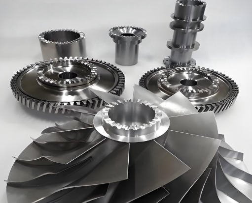
- Turbine blades, impellers, and blisks with twisted airfoil shapes.
- Medical implants with anatomical contours.
- Injection molds with complex cavity surfaces and draft angles.
Being able to orient the tool normal to the surface enables uniform scallop heights and consistent surface quality on complex geometries.
Reduction of Setups and Consolidation of Operations
With 5-axis capability, multiple faces of a part can often be machined in a single setup. This reduces:
- Setup time and operator intervention.
- Fixturing complexity and associated costs.
- Cumulative error from repeated re-clamping.
By consolidating operations, the risk of misalignment between features on different sides of a part is reduced, improving dimensional consistency.
Improved Tool Life and Surface Finish
5-axis machining allows the programmer to choose tool angles that maintain optimal contact conditions. Benefits include:
- Use of shorter, more rigid tools due to better approach angles.
- Reduced tool deflection, improving dimensional accuracy.
- Improved chip evacuation when the tool is oriented to promote chip flow.
These factors contribute to longer tool life and more consistent surface finishes, especially in hard materials and on contoured surfaces.
Higher Accuracy and Tighter Tolerances
When properly set up and calibrated, 5-axis machines can maintain high dimensional accuracy across multiple faces and orientations. Having a single reference setup and using integrated probing minimizes error accumulation. As a result, features that span multiple sides of a part or require precise angular relationships can be produced with tight tolerances.
Typical Applications and Industries Using 5-Axis Machining
5-axis machining is applied wherever complex parts and high precision are required. Some typical application areas include:
Aerospace Components
Aerospace applications include:
- Turbine blades, vanes, and blisks for jet engines.
- Structural components with pockets and ribs, such as wing ribs and bulkheads.
- Complex housings and casings with multiple mounting and sealing surfaces.
These parts often involve high-strength materials such as titanium and nickel-based superalloys, where efficient 5-axis toolpaths are particularly valuable.
Automotive and Motorsport Parts
In automotive, especially motorsport and racing, 5-axis machining is used for:
- Cylinder heads and combustion chambers with optimized flow paths.
- Intake and exhaust manifolds with smooth internal passages.
- Lightweight structural components and prototype parts.
5-axis capability enables precise control of port geometry and surface finish, important for performance and emissions considerations.
Medical Devices and Implants
Medical applications include:
- Orthopedic implants such as knee, hip, and spinal components with complex organic shapes.
- Surgical instruments requiring ergonomic forms and fine details.
- Dental implants and abutments requiring multi-angle machining.
5-axis machining provides the geometric flexibility and precision needed for patient-specific and small, intricate components.
Mold, Die, and Tooling Manufacturing
Mold and die makers use 5-axis machines to produce:
- Injection mold cavities and cores with complex 3D surfaces and undercuts.
- Die-casting and forging dies with contoured surfaces.
- Trimming dies and fixtures with multidirectional features.
5-axis machining can reduce manual polishing by generating smoother surfaces and allows better access to deep cavities without excessively long tools.
Energy, Marine, and Other Applications
Additional applications include:
- Impellers, pump housings, and compressor components in energy and fluid handling sectors.
- Propellers and hydrofoils in marine industries.
- Precision components in industrial equipment and specialized machines.
Wherever complex surfaces, angular relationships, and tight tolerances are needed, 5-axis machining is a strong candidate.
Programming and Toolpath Strategies for 5 Axes
Effective use of 5-axis machines depends heavily on appropriate programming strategies. CAM systems provide various multi-axis toolpath types designed for different geometries and requirements.
Tool Axis Control and Orientation Strategies
Tool axis control is central to 5-axis programming. Common orientations include:
- Normal to surface: Tool axis is kept perpendicular to the local surface, common in finishing free-form surfaces.
- Lead and lag angles: Tool is tilted slightly ahead or behind the direction of travel to improve chip flow and surface quality.
- Fixed tilt within limits: Tool is maintained within defined angular limits to avoid axis limit violations or collisions.
Programmers select tool axis strategies based on the material, cutter type, machine kinematics, and geometric constraints.
Common 5-Axis Toolpath Types
Typical 5-axis toolpath categories include:
- Multi-axis surface finishing: Follows selected surfaces with continuous tilt and smooth motion, often for final finishing passes.
- Swarf milling: Uses the side of a cylindrical or conical tool to cut along ruled surfaces, maintaining constant contact along the tool flank.
- Blade and impeller machining: Specialized strategies for machining blades, hubs, and fillets in turbomachinery components.
- 5-axis drilling and hole making: Automatically orients the tool to drill, ream, or tap holes at arbitrary angles.
Each strategy involves specific parameters for step-over, step-down, tilt limits, and collision avoidance that must be tuned for the part and machine.
Collision Avoidance and Verification
Because the tool, holder, spindle head, and workpiece can be in many relative orientations, collision avoidance is a vital part of 5-axis programming. CAM systems support collision checking against:
- Tool and holder geometry.
- Spindle and head geometry.
- Fixtures, clamps, and machine elements if modeled.
Offline simulation is used to verify toolpaths and detect potential collisions or overtravels before running the program on the machine. Accurate machine models and kinematics in the simulation environment increase confidence in the generated toolpaths.
Accuracy, Tolerances, and Influencing Factors
The accuracy of 5-axis machining is determined by the machine structure, control system, thermal environment, fixturing, and programming. Achievable tolerances on high-quality 5-axis machines are often in the range of a few micrometers for linear dimensions and a few arc-seconds for angular positioning, depending on machine grade and part size.
Geometric and Kinematic Errors
Typical error sources include:
- Linear axis positioning errors: Backlash, scale errors, and straightness deviations.
- Rotary axis errors: Eccentricity, tilt, and backlash in rotary joints.
- Squareness and alignment errors between axes.
In 5-axis machines, combined kinematic errors can lead to tool tip deviations when the tool is tilted and rotated. Compensations in the control can correct for many of these effects if the machine is properly calibrated and maintained.
Thermal Effects and Environmental Conditions
Temperature changes can cause expansions or contractions in machine components, affecting accuracy. Factors include:
- Spindle heating during prolonged high-speed operation.
- Warm-up of axis drives and ball screws.
- Ambient temperature variations in the workshop.
High-end machines integrate thermal compensation, symmetric structures, and cooling systems to stabilize conditions. For precision work, warm-up cycles and controlled environments are used to minimize thermal drift.
Workholding, Tool Deflection, and Process Stability
Even with an accurate machine, process-related factors influence the final part accuracy:
- Fixture rigidity: Insufficient stiffness can cause part movement under cutting loads.
- Tool deflection: Long or slender tools bend under load, leading to dimensional errors on the part.
- Cutting parameters: Aggressive feeds and depths can increase deflection and vibration.
Process planning involves selecting appropriate tools, cutting parameters, and fixturing solutions to keep deflection and vibration within acceptable limits.
Machine Selection Parameters for 5-Axis Machining
Selecting a 5-axis CNC machine requires matching machine capabilities to the intended application. Important selection criteria include:
| Parameter | Relevance | Typical Considerations |
|---|---|---|
| Linear Axis Travels | Determines maximum part size and reachable features | Choose X, Y, Z ranges slightly larger than your largest parts and fixtures |
| Rotary Axis Ranges | Defines accessible angles for tool orientation | Prefer wide tilt ranges (e.g., ±110°) and full C-axis rotation when possible |
| Spindle Speed and Power | Affects material removal and finish across materials | High speed for aluminum and plastics, high torque for steel, titanium, and superalloys |
| Machine Kinematics | Impacts rigidity, accuracy, and application fit | Trunnion for smaller complex parts, head-head for large heavy components |
| Axis Accuracy and Repeatability | Defines achievable tolerances | Check specified linear and rotary accuracies, look for encoder and feedback specifications |
| Tool Magazine Capacity | Influences automation and part family flexibility | Larger tool magazines support complex parts and unattended machining |
| Control Capabilities | Determines 5-axis performance and ease of programming | Support for 5-axis interpolation, TCP, advanced look-ahead, and user-friendly interface |
| Probing and Automation Options | Enhances setup, in-process verification, and unattended operation | Consider spindle probes, tool setters, pallet changers, and robot integration |
Matching these parameters with the intended task list helps ensure that the machine provides the required performance and accuracy without overspecification.
Workholding, Tooling, and Setup Considerations
Effective 5-axis machining relies on robust workholding, appropriate tooling, and optimized setups that account for changing orientations and tool access requirements.
Workholding Strategies for 5-Axis Access
Because tools can approach the workpiece from many angles, workholding must allow ample clearance while maintaining rigidity. Typical strategies include:
- Using risers to lift the workpiece above the table, improving access to side surfaces.
- Minimizing fixture bulk and avoiding tall, flexible structures that may vibrate.
- Designing dedicated fixtures that hold the workpiece securely while leaving critical surfaces exposed.
Tooling and Tool Holder Selection
Tool selection affects cutting performance and accessibility in 5-axis machining:
- Cutter geometry: Ball-end and barrel tools are common for surface finishing, while end mills and drills are used for roughing and hole-making.
- Tool length: Short tools increase stiffness but must be long enough to reach deep features at tilted angles.
- Holder type: Shrink-fit, hydraulic, and collet chucks are typical choices, selected based on balance requirements and runout tolerance.
Tool libraries in CAM software should include accurate geometries for both cutters and holders to enable reliable collision detection and simulation.
Setup Optimization and Coordinate Systems
In 5-axis machining, careful management of coordinate systems is essential. Practices include:
- Defining clear part datums for X, Y, Z, and angular orientation references.
- Using multiple work coordinate systems (WCS) when machining multiple parts or faces within the same cycle.
- Employing probing routines to automatically set and verify WCS positions.
Optimized setups reduce manual alignment time, improve repeatability, and simplify program reuse for similar parts.
Material Considerations in 5-Axis Machining
5-axis machining is applied to a wide range of materials, from light alloys to high-temperature superalloys. Material properties influence tool selection, cutting parameters, and cooling strategies.
Aluminum and Light Alloys
Aluminum and other light alloys are generally machinable at high cutting speeds with moderate cutting forces. In 5-axis machining:
- High spindle speeds and feed rates can be used with appropriate tools.
- Toolpaths can be optimized for continuous, high-speed motion across surfaces.
- Chip evacuation must be managed to prevent recutting and surface damage.
Steels, Stainless Steels, and Tool Steels
Steels and stainless steels require more cutting force and generate higher tool loads:
- Moderate spindle speeds with higher torque are advantageous.
- Cutting parameters must balance removal rate and tool life.
- Tool coatings and high-performance carbide grades are often used.
In mold and die applications, hardened tool steels demand careful selection of finishing strategies to achieve required surface quality and dimensional accuracy.
Titanium, Superalloys, and Hard-to-Cut Materials
Materials such as titanium alloys and nickel-based superalloys present higher mechanical and thermal loads on tooling. For 5-axis machining of these materials:
- Cutter engagement should be carefully controlled using adaptive strategies and optimized tool orientations.
- Lower spindle speeds, higher torque, and high-pressure coolant are often used.
- Tools must be selected based on heat resistance, wear resistance, and geometry tailored for these materials.
5-axis capability can be used to minimize tool overhang and maintain favorable engagement angles, contributing to better tool life and dimensional control in hard-to-cut materials.
Process Planning and Optimization in 5-Axis Machining
Process planning organizes operations, tools, and setups to achieve quality and efficiency goals. In 5-axis machining, planning must account for machine kinematics and multi-orientation workflows.
Operation Sequencing
Sequencing operations involves deciding the order of roughing, semi-finishing, and finishing, as well as drilling and other features. Considerations include:
- Maintaining stability: Roughing bulk material first while preserving enough material to support subsequent cuts.
- Minimizing setup changes: Grouping operations by orientation and workholding conditions.
- Managing tool changes: Grouping operations by tool to reduce tool change time while respecting geometry constraints.
Toolpath and Parameter Optimization
Optimizing toolpaths and parameters can improve both cycle time and part quality. Techniques include:
- Using consistent step-over for uniform surface finish on free-form surfaces.
- Adjusting feed rates in regions of high curvature or sudden direction changes.
- Selecting appropriate lead/lag angles to improve cutting efficiency and surface integrity.
Continuous improvement is often achieved by reviewing initial runs, measuring results, and refining toolpaths and parameters for subsequent batches.
Quality Control and Inspection
Inspection practices confirm that the machined part meets specifications. For 5-axis parts, common approaches are:
- In-process probing: Measuring critical features on the machine to detect deviations early.
- Coordinate Measuring Machines (CMM): External inspection with tactile or optical probing to verify dimensions and surface forms.
- Surface finish measurement: Using profilometers or optical instruments to assess roughness on complex surfaces.
Feedback from inspection can be used to adjust tool wear compensation, offset values, and in some cases to update CAD/CAM models for improved accuracy on future runs.
Unlock the Power of 5-Axis Machining with XCM
At XCM, we don’t just explain what 5-axis machining is – we use it every day to push the limits of what’s possible for our customers. From complex aerospace components to high-precision mold parts, our 5-axis CNC capabilities allow us to achieve tighter tolerances, better surface finishes, and shorter lead times than traditional 3-axis machining. If you’re looking to reduce setups, improve part accuracy, and bring more ambitious designs to life, XCM’s 5-axis machining services are ready to support your next project.
FAQ About 5-Axis Machining
What is 5-axis machining?
5-axis machining is a CNC process where the cutting tool moves along five different axes simultaneously, allowing the creation of complex 3D shapes in a single setup.
How is 5-axis different from 3-axis machining?
While 3-axis machines move along X, Y, and Z axes, 5-axis machines add rotational movements (A and B axes). This allows machining of angled surfaces, undercuts, and intricate geometries without repositioning the part.
What are the main advantages of 5-axis machining?
Machining complex parts in a single setup
Improved surface finish and accuracy
Reduced manual repositioning
Shorter production time and lower labor costs
Is 5-axis machining more expensive than 3-axis machining?
Yes, the machines and programming are more advanced, so initial costs are higher, but efficiency gains, fewer setups, and higher precision can reduce overall production costs.
What types of parts benefit most from 5-axis machining?
Parts with complex 3D surfaces, undercuts, angled features, turbine blades, impellers, molds, and prototypes benefit greatly from 5-axis machining.
