
CNC machining centers with 3-axis and 4-axis configurations represent two of the most widely used solutions in modern manufacturing. Understanding the differences between 4 axis CNC and 3 axis CNC machines is essential for making correct equipment investments, planning machining processes, and achieving the desired balance of productivity, precision, and cost.
Fundamental Concepts of 3 Axis and 4 Axis CNC
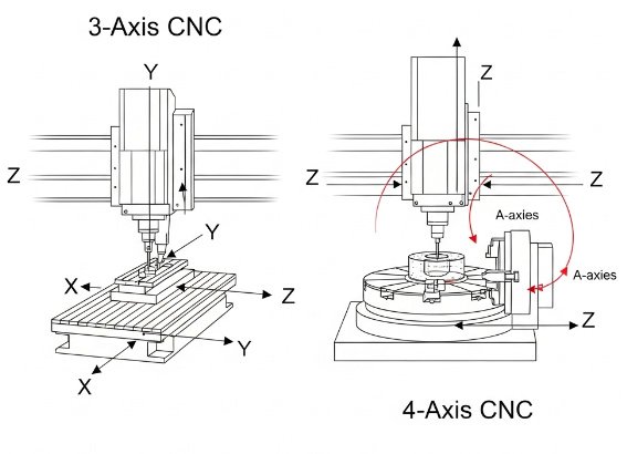
Both 3 axis and 4 axis CNC machines are built on a Cartesian coordinate system, but they differ in the number of linear and rotary axes they can control simultaneously. Before comparing them in detail, it is important to clarify the definition of axes and typical motion configurations.
Linear and Rotary Axes Overview
In CNC terminology, each axis represents an independent direction of motion that the machine tool can control. These motions are typically categorized as follows:
- Linear axes: X, Y, and Z movements along straight lines
- Rotary axes: A, B, and C rotations around the X, Y, and Z axes respectively
Most milling-based machining centers use:
- X-axis: left-right movement of the table or gantry
- Y-axis: front-back movement of the table or headstock
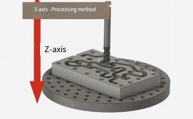
- Z-axis: up-down movement of the spindle or quill
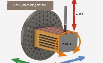
When a fourth axis is added, it is commonly a rotary axis designated as A (rotation around X) or sometimes B (rotation around Y). This rotary axis is often implemented as a rotary table, trunnion, or indexer mounted on the main machine table.
What Is a 3 Axis CNC Machine?
A 3 axis CNC machine is a machining center or milling machine that controls movement along the three primary linear axes: X, Y, and Z. The cutting tool approaches the workpiece from a single direction, usually vertically in the case of vertical machining centers (VMCs) or horizontally in horizontal machining centers (HMCs).
Key characteristics of 3 axis CNC machines include:
- Tool moves along X, Y, and Z axes only
- Workpiece remains fixed except for fixturing and manual repositioning
- Multiple setups may be required for multi-face machining
- Suitable for prismatic components, flat surfaces, and relatively simple 3D contours
3 axis machines are widely used because of their simplicity, relatively lower cost, and broad compatibility with common machining tasks.
What Is a 4 Axis CNC Machine?
A 4 axis CNC machine adds one controlled rotary axis to the three standard linear axes. Most commonly, a rotary table provides an A-axis (rotation around X) or B-axis (rotation around Y). This allows the workpiece to rotate under the cutting tool, enabling machining from multiple orientations without manual repositioning.
Characteristics of 4 axis CNC machines include:
- Three linear axes (X, Y, Z) plus one rotary axis (usually A or B)
- Capability for indexing (stepwise rotation) or continuous rotary motion
- Enhanced access to multiple sides of the workpiece in a single setup
- Improved productivity and accuracy in multi-face or cylindrical machining
4 axis machines bridge the gap between basic 3 axis machines and more complex multi-axis configurations, providing a practical solution for parts requiring multi-side machining and detailed features on cylindrical or complex shapes.
Mechanical Structure and Axis Configuration
The mechanical design of 3 axis and 4 axis CNC machines determines their stiffness, accuracy, and usability. While many components are similar, the addition of a fourth axis introduces distinct structural and kinematic characteristics.
3 Axis Machine Structure
Typical 3 axis CNC mill structures include:
1) Vertical Machining Center (VMC)
In a VMC, the spindle is oriented vertically. The most common configuration is:
- Table moves in X and Y
- Spindle head moves in Z
This design offers good visibility and ease of part loading, making it popular for general machining work. The table is usually stationary in Z, which simplifies fixture design for many parts.
2) Horizontal Machining Center (HMC)
In an HMC, the spindle is oriented horizontally, and the table often rotates as a built-in B-axis, although here we consider the base 3-axis variant as linear X, Y, Z only. HMCs offer benefits for chip evacuation and high-volume production but are structurally more complex.
4 Axis Machine Structure
In most cases, 4 axis CNC machines are essentially 3 axis machining centers equipped with an additional rotary device. Common implementations include:
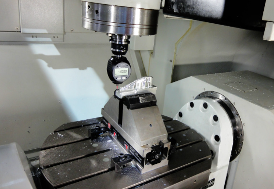
1) Add-On Rotary Table (A-Axis)
A rotary table is mounted on the machine table, providing rotation around the X-axis. Features:
- Workpiece mounted on the rotary table faceplate or fixture
- Allows positioning at multiple angles for multi-side machining
- Can be used as indexing (fixed positions) or continuous rotational axis
2) Trunnion Table
A trunnion table combines a rotary axis with a tilting or swiveling table. For many 4 axis systems, only one rotary axis is fully controlled, while the other is locked or used for setup adjustment. Advantages of trunnion designs include improved access to the workpiece and reduced fixture height.
Mechanical considerations specific to 4 axis structures include:
- Rotary bearing stiffness and backlash control
- Clamping torque capacity for holding the workpiece under cutting forces
- Rotary encoder resolution for accurate angular positioning
These elements have a direct impact on the achievable tolerance and surface quality when using the fourth axis.
Motion Capabilities and Machining Operations
The difference in motion capabilities between 3 axis and 4 axis CNC machines directly influences the types of operations that can be performed, the number of setups required, and the achievable geometries.
Typical Operations on 3 Axis CNC Machines
On a 3 axis CNC, the cutting tool can move in X, Y, and Z simultaneously. This enables a wide range of operations:
- Facing, contouring, and pocket milling on flat surfaces
- Drilling, tapping, and reaming operations normal to a single plane
- 2D and 2.5D machining, including slots, pockets, and profile contours
- 3D surface machining using ball-end mills for components such as molds and dies
However, access is limited to the surfaces reachable from the primary setup orientation. To machine features on different faces of a part (for example, side holes or features on opposite sides), the operator must:
- Stop the machine
- Loosen the part from the existing fixture
- Reorient and re-clamp the part
- Re-find datums or coordinate systems
This manual intervention increases setup time and introduces opportunities for positioning errors.
Typical Operations on 4 Axis CNC Machines
With a rotary axis added, a 4 axis CNC machine can perform additional operations that are not possible or not efficient on 3 axis machines:
- Multi-face machining in one setup by rotating the part
- Machining of cylindrical and conical surfaces with synchronized rotation
- Helical milling along a rotary axis (e.g., engraving on round parts)
- Drilling holes at different angular positions around a cylinder
The rotary axis can be used in two principal ways:
1) Indexing Mode
In indexing operation, the fourth axis rotates the part to a defined angle and locks in position. Machining then takes place using only X, Y, and Z axis motions. This is common for:
- Machining prismatic parts on multiple faces
- Creating features at specific angular positions
- Ensuring repeatable orientation with high clamping torque
2) Continuous or Simultaneous 4 Axis Mode
In continuous 4 axis machining, the rotary axis moves simultaneously with the linear axes. This allows the tool to trace complex paths around the workpiece, useful for:
- Profiling around cylindrical components
- Machining turbine-like shapes with rotation around one principal axis
- High-precision cylindrical engraving or fluting
While continuous 4 axis machining increases flexibility, it also requires more advanced programming and careful control of feed rates and accelerations.
Accuracy, Repeatability, and Surface Quality
The achievable accuracy and surface quality depend on machine design, component quality, and control parameters. Adding a fourth axis introduces new elements that can influence both static and dynamic precision.
Accuracy in 3 Axis CNC Machines
In a 3 axis machine, key contributors to accuracy include:
- Linear guide and ball screw quality (pitch error, backlash)
- Thermal stability of the machine structure
- Position feedback system resolution (linear encoders or motor encoders)
- Kinematic calibration and compensation tables
Common specifications for industrial-grade 3 axis machining centers include:
- Linear positioning accuracy: approximately ±0.005 mm to ±0.02 mm over the working volume (values vary by machine class)
- Repeatability: often within ±0.003 mm to ±0.01 mm
- Surface roughness (Ra): can reach low micrometer levels with optimized cutting conditions and tool choice
Because all axes are linear, system errors can be modeled and compensated with relatively straightforward methods.
Accuracy in 4 Axis CNC Machines
For 4 axis machines, all factors influencing 3 axis accuracy also apply, but rotary-axis-specific factors must be considered:
- Rotary encoder resolution and accuracy (e.g., arcsecond-level requirements)
- Rotary bearing and gear backlash
- Clamping system rigidity under cutting loads
- Radial and axial runout of the rotary table
Typical rotary axis specifications on standard 4 axis add-ons or machine-integrated rotaries may include:
- Indexing accuracy: from ±5 arcseconds to ±30 arcseconds, depending on quality
- Repeatability: often superior to absolute accuracy, within a few arcseconds
- Clamping torque: from several hundred to several thousand N·m, depending on table size
When properly configured and calibrated, a 4 axis machine can maintain comparable linear accuracy to a 3 axis machine while offering additional orientation accuracy. However, improper rotary axis alignment or inadequate clamping can degrade overall precision, particularly for tight-tolerance multi-face relationships.
Capabilities and Limitations
Choosing between 3 axis and 4 axis CNC involves evaluating what each can and cannot do relative to specific part requirements.
Capabilities of 3 Axis CNC Machines
3 axis machines are highly capable for many categories of parts, including:
- Flat plates with pockets, holes, and contours
- Brackets and blocks requiring machining from one or two primary faces
- Dies, molds, and cavities with 3D surface features primarily accessible from one direction
Advantages include:
- Simpler programming and setup
- Lower machine acquisition and maintenance costs
- Shorter learning curve for operators and programmers
However, limitations arise when parts require:
- Accurate features on multiple faces with tight positional relationships
- Angular drilling or milling operations on cylindrical surfaces
- Complex geometries that cannot be accessed from a single primary direction
In such cases, multiple setups and complex fixtures are needed, which can increase cumulative error and overall cycle time.
Capabilities of 4 Axis CNC Machines
4 axis CNC machines extend the capability of 3 axis systems, particularly for:
- Parts requiring machining on several sides in a single setup
- Cylindrical components with features distributed around the circumference
- Components that benefit from synchronized rotation and linear motion
Benefits include:
- Reduced number of setups and clamping operations
- Improved positional accuracy between features on different faces
- Enhanced productivity for multi-side machining tasks
Limitations to consider:
- Still not suitable for fully freeform undercuts and complex 3D shapes requiring access from many directions (these often require 5 axis machining)
- Fixture design can be more complex due to rotational movement and clearance requirements
- Rotary axis travel range and torque may limit the size and weight of parts
For many shops, 4 axis machines provide an effective step up from 3 axis without the complexity and investment required for full 5 axis equipment.
Applications and Part Types
The selection between 3 axis and 4 axis CNC machines must be aligned with the typical applications and part geometries encountered in production.
Typical Applications for 3 Axis CNC
3 axis machines are common in:
- General mechanical component manufacturing
- Plate work with patterns of holes and pockets
- Mold and die machining where most features are accessible from one direction
- Prototype machining and short-run production with moderate complexity
- Fixtures and tooling fabrication where shapes are prismatic
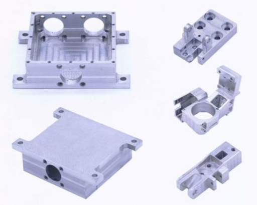
Specific part examples include:
- Base plates, mounting plates, and covers
- Machine brackets and supports
- Injection mold cavities with a primary machining direction
- Simple housings and enclosures
Typical Applications for 4 Axis CNC
4 axis machines are used when the part geometry requires more than one main orientation but not the full flexibility of 5 axis machining. Typical applications include:
- Shafts, axles, and cylindrical parts with flats, keyways, and cross-holes
- Valves, manifolds, and fittings with ports on multiple sides
- Turbine-like parts and impellers with rotational symmetry around one axis
- Engraving and patterning around cylindrical surfaces
Typical industries using 4 axis machining include:
- Automotive: components such as camshafts, crank components, and flanged shafts
- Aerospace: structural parts with multiple faces and angular features around a primary axis
- Medical: orthopedic implants and instruments with complex circumferential geometry
- Energy: small turbine and compressor components requiring rotary indexing
In many cases, a 4 axis machine can substantially reduce machining time and fixture complexity for such parts compared to purely 3 axis equipment.
Programming, CAM, and Control Considerations
Programming 3 axis and 4 axis CNC machines differs in complexity, required CAM software features, and CNC control configuration. These factors affect the workflow from CAD model to finished part.
Programming for 3 Axis CNC
In 3 axis machining, toolpaths can be defined by:
- Manual G-code programming for simpler operations (e.g., drilling cycles, basic pockets)
- CAM-generated toolpaths for 2D contouring and 3D surface machining
Standard 3 axis toolpath types include:
- Profile milling
- Pocket milling
- Drilling and tapping cycles
- Parallel, zig-zag, or spiral finishing for 3D surfaces
The CNC control interprets the program as a sequence of commands controlling X, Y, and Z axes, with optional spindle speed and feed overrides. The primary complexity lies in selecting appropriate strategies for material removal, choosing tools, and defining cutting parameters.
Programming for 4 Axis CNC
4 axis programming adds rotary motion to the toolpath definition. There are two main scenarios:
1) Indexing 4 Axis Programming
In indexing mode, the programmer defines several workpiece orientations. The rotary axis moves to specified angles (e.g., A0, A90, A180 degrees). For each orientation, the machining is similar to traditional 3 axis programming. Key aspects include:
- Defining separate work coordinate systems (e.g., G54, G55) for each angular position
- Ensuring consistent datum relationships between different orientations
- Verifying collision clearance for fixtures and spindle at each angle
2) Continuous 4 Axis Programming
In continuous 4 axis machining, toolpaths must incorporate simultaneous changes in X, Y, Z, and the rotary axis. CAM software must support:
- Wrapping toolpaths around cylindrical surfaces
- Synchronized motion between linear and rotary axes
- Management of feed rates in linear and angular terms
The CNC control must support coordinated interpolation of four axes. Additional parameters often include maximum rotary acceleration and jerk limits to prevent mechanical stress and maintain surface quality.
Verification and simulation become especially important when using continuous 4 axis strategies to avoid collisions and to ensure the tool maintains the required contact conditions during rotation.
Workholding, Fixtures, and Setup
Workholding strategy is a crucial element in both 3 axis and 4 axis machining. The presence of a rotary axis changes fixture design requirements and setup procedures.
Workholding on 3 Axis Machines
On 3 axis machines, common workholding devices include:
- Machine vises
- Clamping kits on T-slot tables
- Custom fixtures and dedicated jigs
- Magnetic and vacuum chucks for specific materials and geometries
In multi-face machining, fixtures may incorporate locating pins, stops, and reference surfaces to allow the part to be repositioned while maintaining datums. However, each manual repositioning introduces potential errors from clamp deformation, misalignment, and operator variation.
Workholding on 4 Axis Machines
With a rotary table or trunnion, workholding must meet two main requirements:
- Secure clamping under cutting forces at various angular positions
- Geometric alignment with the rotary axis to ensure accurate rotation relative to part features
Common workholding solutions for 4 axis machining include:
- 4 jaw chucks mounted on rotary tables for round or irregular parts
- Collet fixtures for shafts and bar-like workpieces
- Dedicated multi-part fixtures designed to hold several components along the rotary axis
- Fixture plates bolted to the rotary table with standardized locating patterns
Key considerations for 4 axis fixture design:
- Center of gravity: the part should be balanced around the rotary axis to reduce load on bearings and motors
- Clearance: fixtures must allow tool access around the rotated part without collisions
- Rigidity: clamping forces must resist tangential forces during cutting at different angular positions
Setups on 4 axis machines often require an additional step of rotary axis alignment, such as using dial indicators or probing cycles to ensure the axis of rotation is correctly aligned in the machine coordinate system.
Cycle Time, Throughput, and Productivity
Productivity differences between 3 axis and 4 axis CNC machines stem mainly from setup time, tool access efficiency, and the ability to process multiple faces without manual intervention.
Cycle Time on 3 Axis Machines
On 3 axis machines, overall cycle time per part is composed of:
- Pure cutting time (tool in contact with material)
- Non-cutting movements (rapid traverses, tool changes)
- Manual operations (re-clamping, datum re-establishment, inspection between setups)
For parts requiring multiple orientations, the time spent on manual steps can be significant, especially in small and medium batch sizes. Each additional setup introduces a fixed time component that is repeated per batch, and can also increase the likelihood of scrap if positioning errors occur.
Cycle Time on 4 Axis Machines
4 axis machines can reduce cycle time by eliminating or minimizing manual re-clamping stages. For example:
- Multi-side machining is executed in one continuous program, rotating the part automatically
- Angular drilling and milling operations around a cylinder can be performed in a single setup
Resulting benefits may include:
- Shorter per-part machining time for complex or multi-face components
- Reduced non-cutting time related to workpiece handling
- Improved throughput in production environments with repeated batches
However, on simpler parts that only require one face, the 4 axis capability may not provide a cycle-time advantage over 3 axis machines. In such cases, the primary factors remain spindle power, tool path optimization, and rapid traverse speeds rather than axis count.
Cost, Investment, and Maintenance
The total cost of ownership for 3 axis and 4 axis CNC machines includes initial purchase, tooling and fixtures, software, training, and ongoing maintenance. The fourth axis adds both investment and operational considerations.
Acquisition Cost Differences
Cost elements for 3 axis CNC machines include:
- Base machine (structure, spindle, control, linear axes)
- Tooling packages (toolholders, cutting tools)
- Basic fixtures (vises, clamps)
- Standard 3 axis CAM software licenses
When moving to 4 axis, additional cost elements appear:
- Rotary table or trunnion attachment or machine with integrated 4th axis
- More advanced CAM software supporting 4 axis operations
- Specialized fixtures for rotary workholding
- Potentially higher machine specification to support additional axis loads
Therefore, 4 axis configurations typically involve higher initial investment than comparable 3 axis systems. The decision must be justified by part mix, throughput requirements, and reduction in manual labor or setups.
Operating and Maintenance Considerations
Additional maintenance factors for 4 axis machines include:
- Rotary axis lubrication and seal inspection
- Periodic verification of rotary indexing accuracy
- Monitoring of gear or belt wear in the rotary drive
For both 3 axis and 4 axis machines, routine tasks include:
- Guideway and ball screw lubrication
- Spindle condition monitoring
- Coolant system cleaning and filtration maintenance
- Verification of linear axis accuracy and backlash
From an operational perspective, 4 axis machines may reduce manual labor for re-clamping and measuring multi-face relationships, which can offset higher machine complexity in environments with suitable part families.
Comparison Summary: 4 Axis CNC vs 3 Axis CNC
The following table organizes key technical and practical differences between 3 axis and 4 axis CNC machines for quick reference.
| Aspect | 3 Axis CNC | 4 Axis CNC |
|---|---|---|
| Controlled Axes | X, Y, Z (linear) | X, Y, Z (linear) + A or B (rotary) |
| Typical Machine Base | Vertical or horizontal machining center | 3 axis base with rotary table or trunnion |
| Workpiece Orientation | Single primary orientation per setup | Multiple orientations in one setup via rotation |
| Multi-Face Machining | Requires multiple setups and manual re-clamping | Performed automatically by indexing or continuous rotation |
| Cylindrical Surface Machining | Limited; often requires custom fixtures or turning | Well-suited for radial features and wrapped toolpaths |
| Programming Complexity | Lower; focus on 2D/3D paths in X, Y, Z | Higher; must manage rotary axis, indexing, or simultaneous motion |
| Fixture Complexity | Typically simpler, but more setups | More complex fixtures for rotation; fewer setups |
| Positional Accuracy Between Faces | Dependent on manual repositioning accuracy | Improved by CNC-controlled indexing and consistent datums |
| Initial Machine Cost | Lower for comparable size and quality | Higher due to rotary hardware and control capability |
| Typical Applications | Plates, brackets, molds, prismatic parts | Shafts, manifolds, multi-side parts, cylindrical engraving |
| Operator Skill Requirement | Moderate; well-known workflows | Higher; requires understanding of rotary kinematics and 4 axis CAM |
Key Technical Parameters to Evaluate
When comparing specific 3 axis and 4 axis machines, certain technical parameters should be examined beyond the basic axis count. These parameters directly affect the suitability of the machine for target parts and materials.
Spindle Specifications
Both 3 axis and 4 axis machines share similar spindle-related considerations:
- Spindle power (kW or HP): determines material removal capacity, especially for heavy roughing.
- Maximum spindle speed (rpm): important for small tools and high-speed machining of aluminum or plastics.
- Spindle taper (e.g., BT30, BT40, HSK): affects toolholder rigidity and changeover options.
- Runout and thermal stability: influence surface finish and tool life.
For 4 axis machines used for complex contours or finishing around cylinders, stable spindle behavior at varying orientations and feed rates is important to achieve consistent surface quality.
Axis Travels and Rotary Capabilities
Linear travels and rotary specifications must match the expected part envelope. Important values include:
- X, Y, Z travel ranges: define maximum workpiece and fixture size.
- Rotary axis swing diameter: maximum part diameter that can rotate without collision.
- Rotary axis load capacity: maximum permissible workpiece mass.
- Rotary travel range: for example, ±120 degrees or full 360-degree continuous rotation.
Inadequate rotary axis load capacity or swing diameter can restrict the practical use of 4 axis capabilities, especially for larger components.
Feed Rates and Acceleration
Rapid traverse speeds and axis acceleration influence non-cutting time and responsiveness in high-speed machining:
- Maximum rapid feed in X, Y, Z (e.g., 20–60 m/min for many modern machines).
- Maximum rotary speed (degrees per second or rpm).
- Acceleration and deceleration rates for linear and rotary axes.
For continuous 4 axis machining, balanced accel/decel values across linear and rotary axes help maintain smooth toolpaths, which is critical for surface quality and tool life.
Selection Guidelines: When to Choose 3 Axis or 4 Axis
Choosing between 3 axis and 4 axis CNC machines depends on part requirements, production volumes, budget, and available expertise. The following guidelines summarize typical selection logic.
When a 3 Axis CNC Is Appropriate
3 axis machines are usually sufficient when:
- Most parts are prismatic or plate-like with features accessible from one or two primary directions.
- Angular or circumferential features are rare or can be handled manually.
- Batch sizes are small and the time spent on extra setups is acceptable.
- Budget is limited and there is a need to minimize acquisition cost and complexity.
- Operator and programmer experience is primarily in 3 axis workflows.
For many job shops focused on general machining tasks, a well-equipped 3 axis machining center can handle a large portion of customer requirements with high efficiency.
When a 4 Axis CNC Is Appropriate
A 4 axis machine becomes advantageous when:
- Parts regularly require features on multiple sides with tight positional tolerances between faces.
- There is a recurring need to machine cylindrical components with milled flats, keyways, slots, or radial hole patterns.
- Batch sizes are moderate to high, so savings in setup time and reduced handling translate into significant productivity gains.
- The shop is prepared to invest in 4 axis CAM capabilities and appropriate training.
- Future work is expected to include more complex geometries around one primary rotational axis.
In such environments, the 4 axis machine can deliver measurable improvements in throughput, consistency, and reduction of manual operations compared with 3 axis-only setups.
Practical Pain Points and Considerations
In real production environments, several practical issues often emerge when deciding between or working with 3 axis and 4 axis CNC machines.
Common Pain Points with 3 Axis Only
Typical difficulties when relying solely on 3 axis machines for complex parts include:
- Multiple setups: each additional clamping increases the risk of cumulative error and consumes operator time.
- Complex fixtures: to reach side features, custom fixtures may need to tilt or rotate parts manually, increasing fixture cost and setup complexity.
- Limited accessibility: some geometries simply cannot be produced efficiently with access from a single direction, leading to compromises or subcontracting.
These issues become more pronounced when tolerance requirements are tight or when the part volume justifies investment in more efficient solutions.
Common Pain Points When Adding 4 Axis
Transitioning to 4 axis machining introduces its own considerations:
- Programming learning curve: programmers must understand rotary coordinates, axis wrapping, and safe indexing strategies.
- Collision risk: with rotation and more complex fixtures, careful simulation and clearance checks are necessary to avoid crashes.
- Fixture design complexity: designing fixtures that maintain rigidity and balance during rotation requires additional engineering effort.
- Underutilization risk: if the part mix does not consistently require 4 axis work, the extra investment may not be fully leveraged.
These points highlight the need for realistic assessment of part requirements, programming resources, and long-term workload before upgrading from 3 axis to 4 axis equipment.
Example Use Cases Illustrating 3 Axis vs 4 Axis
The following simplified use cases help illustrate how 3 axis and 4 axis machines differ in practical production scenarios.
Case 1: Prismatic Bracket with Features on Two Faces
Part description: A rectangular aluminum bracket with:
- Mounting holes and pockets on the top face.
- Threaded side holes on one vertical face.
3 axis approach:
- Setup 1: Machine top face features with part clamped in vise.
- Setup 2: Reorient part so side face is upward, re-establish datum, and machine side holes.
4 axis approach:
- Single setup: Clamp part on a rotary fixture, machine top face at A0 degrees, then index to A90 degrees to machine side holes without re-clamping.
Benefits of 4 axis in this scenario include reduced setup time and improved positional accuracy between top and side features.
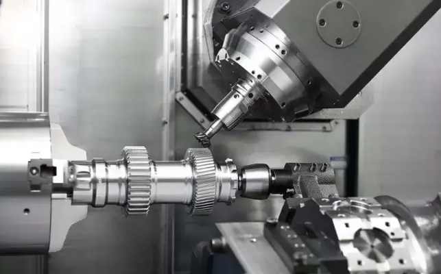
Case 2: Cylindrical Shaft with Multiple Radial Features
Part description: A steel shaft requiring:
- Keyways at specific angular positions.
- Radial holes around the circumference.
- Flats for wrench engagement.
3 axis approach:
- Requires multiple custom fixtures or manual indexing of the part in a vise or chuck.
- Operator must re-orient the shaft several times, measuring angles manually.
4 axis approach:
- Shaft mounted in a chuck on the rotary axis.
- Keyways, flats, and radial holes machined automatically by rotating the shaft to programmed angles (e.g., A0, A90, A180, A270 degrees).
In this case, the 4 axis machine provides a highly efficient and repeatable method to handle circumferential features that would be cumbersome on a 3 axis system.
Tooling Strategies for 3 Axis and 4 Axis CNC
While the fundamental cutting tools used on 3 axis and 4 axis machines are similar, tool selection and strategy can differ when rotary motion is involved.
Tooling on 3 Axis Machines
For most 3 axis operations, standard milling tools are used:
- End mills (flat, ball nose, corner radius) for roughing and finishing.
- Drill bits, taps, and reamers for hole-making.
- Face mills for large surface finishing.
Strategies often include:
- Step-down and step-over definitions for efficient material removal.
- Use of tool length and diameter compensation to maintain accuracy.
- Selection of suitable toolholders (e.g., collet chucks, hydraulic chucks) to maximize rigidity.
Tooling on 4 Axis Machines
In 4 axis machining, the same tool types are used, but additional considerations apply:
- Reach: tools must be long enough to access features at all angular positions without interference with fixtures.
- Chip evacuation: orientation of the part during rotation can affect chip flow; coolant direction and flow rate must be considered.
- Cutting forces: radial and tangential forces change direction with rotation, so tool clamping and fixture rigidity are critical.
- Toolpath smoothness: especially in continuous 4 axis machining, smooth toolpaths reduce vibration and improve surface finish.
For wrapped toolpaths around cylinders, ball-end mills are frequently used to maintain constant contact conditions, and feed rates must be adjusted based on the effective cutting speed at the varying contact points around the circumference.
Data and Parameter Management
Proper management of machine data, work coordinates, and tool parameters is essential for both 3 axis and 4 axis CNC operations, but 4 axis adds extra elements related to rotary position tracking.
Work Coordinate Systems
On 3 axis machines, work coordinate systems (e.g., G54 to G59) define the relationship between machine coordinates and part datums. The same applies to 4 axis machines, with additional complexity:
- Each indexed orientation can have its own work offset, or
- A single offset can be used if the machine control and CAM define rotary motion relative to a fixed datum.
For consistent results, rotary axis zero position must be clearly defined and repeatable. Some shops use mechanical stops or zeroing routines to ensure that the A-axis or B-axis home position is accurately known before each machining cycle.
Tool Length and Radius Compensation
Tool length and radius compensation (e.g., G43, G41, G42 commands) are important for both 3 axis and 4 axis machining. In 4 axis operations, compensation must be consistent across different angular positions, which depends on:
- Precise definition of tool lengths in the tool offset table.
- Accurate modeling of tool and holder geometry in CAM for collision detection.
The use of offline tool presetting equipment and digital tool management systems can help maintain consistent tool data across multiple machines and reduce manual errors.
Integrated Automation and Multi-Station Setups
Both 3 axis and 4 axis machines can be integrated into automated cells with pallet systems, robots, or multi-station setups. However, the presence of a rotary axis influences how such automation is implemented.
Automation with 3 Axis Machines
Common automation solutions for 3 axis machines include:
- Pallet changers that allow one part to be machined while another is being loaded.
- Robotic loading and unloading of parts into vises or fixtures.
- Flexible manufacturing systems (FMS) with multiple machines and shared pallet pools.
Because part orientation is fixed on each pallet, special care is needed when using automation for multi-face parts, often requiring separate fixtures for each orientation.
Automation with 4 Axis Machines
With 4 axis machines, automation can utilize the rotary axis to process different sides of the part without changing fixtures. Advantages include:
- Pallets or fixtures can hold parts in a single orientation while the rotary axis provides access to multiple faces.
- Robots can load cylindrical parts directly into chucks on rotary tables.
- Multi-part fixtures on the rotary axis can allow several parts to be machined per cycle, improving spindle utilization.
System design must ensure that any automated loading aligns the part correctly with the rotary axis to maintain accurate angular relationships.
Summary and Practical Conclusions
Both 3 axis and 4 axis CNC machines play vital roles in modern machining operations. Their core differences can be summarized as follows:
- 3 axis CNC machines provide a robust, cost-effective solution for general prismatic and moderately complex 3D machining where most features are accessible from one or two orientations.
- 4 axis CNC machines add a controlled rotary axis, enabling efficient multi-face and cylindrical machining, reducing the number of setups, and improving positional accuracy between features located at different angles.
The decision to use 3 axis or 4 axis CNC should be based on:
- Part geometry: presence of circumferential features and multi-side requirements.
- Tolerance requirements between features on different faces.
- Production volume: higher volumes favor more automation and reduced manual setups.
- Budget and available technical expertise.
By carefully analyzing these factors and comparing the technical parameters of available machines, manufacturers can select the configuration that provides the best balance of capability, precision, productivity, and cost for their specific machining environment.
