
Turbomachinery is a broad class of rotary fluid machines that exchange energy with a flowing fluid through rotating blades. Typical examples include gas turbines, steam turbines, compressors, pumps, fans, and blowers. These machines are central to power generation, aviation, oil and gas, process industries, HVAC systems and many other engineering applications.
This article explains core principles of turbomachinery, main classifications and machine types, key performance parameters, design and operation aspects, and the machining and manufacturing processes used to produce critical components such as blades, rotors and casings.
Fundamental Principles of Turbomachinery
Turbomachinery operates by transferring energy between a rotor and a fluid. Depending on direction of energy transfer, turbomachinery is classified as:
- Power-generating machines (turbines): Convert fluid energy into mechanical shaft power.
- Power-absorbing machines (compressors, pumps, fans, blowers): Use mechanical power to increase fluid pressure or head.
The principles of operation are derived from conservation of mass, momentum and energy applied to a control volume that includes the rotating blades and flow passages.
Continuity of Mass Flow
For steady operation, the mass flow rate through the machine is constant:
ṁ = ρ A V
where ṁ is mass flow rate, ρ is fluid density, A is flow area, and V is average flow velocity. In compressible machines (e.g., gas compressors, gas turbines) density varies along the flow path; in incompressible approximations (e.g., water pumps), density is assumed constant.
Euler Turbomachinery Equation
The central equation for turbomachinery relates the specific work exchanged with the fluid to the change in angular momentum:
Ws = U2 Vu2 - U1 Vu1
where:
Wsis specific work (J/kg).Uis blade (tangential) speed at radius r:U = ω r.Vuis tangential component of absolute velocity.- Subscripts 1 and 2 denote inlet and outlet of the rotor.
This relation forms the starting point for velocity triangle construction, stage design and estimation of ideal work input (pumps, compressors) or output (turbines).
Velocity Triangles
Flow at rotor inlet and outlet is described using velocity triangles, which resolve the absolute velocity of the fluid into components relative to the rotor:
- Absolute velocity
V - Blade (peripheral) speed
U - Relative velocity
W(velocity of fluid relative to moving blade)
These vectors obey:
V = U + W
Designers use velocity triangles to determine angles of inlet and exit flow, blade angles, meridional velocities, and to evaluate incidence and deviation at design and off-design conditions.
Energy Equation and Head
For incompressible flow (as in pumps and many hydraulic turbines), the energy exchange is commonly expressed as head:
H = Ws / g
where g is gravitational acceleration. The total head includes static pressure head, velocity head and elevation head. In turbines, the head is converted to shaft power; in pumps, shaft power is converted into fluid head.
Compressible Flow Aspects
In compressors and gas/steam turbines, compressibility is significant. Relevant quantities include:
- Total (stagnation) pressure and temperature.
- Static pressure and temperature distributions.
- Mach number (ratio of flow speed to local speed of sound).
Performance is often expressed using isentropic relations and temperature/pressure ratios, such as compressor pressure ratio and turbine expansion ratio.
Classification of Turbomachinery
Turbomachinery can be classified in several ways: by fluid type, primary purpose, flow direction, and thermodynamic behavior.
Classification by Function
| Category | Energy Direction | Typical Machines | Common Applications |
|---|---|---|---|
| Turbines | Fluid → Shaft | Gas turbines, steam turbines, hydraulic turbines | Power generation, propulsion, mechanical drives |
| Compressors | Shaft → Gas | Axial compressors, centrifugal compressors | Gas turbines, process gas, refrigeration |
| Pumps | Shaft → Liquid | Centrifugal pumps, mixed-flow pumps | Water supply, process liquids, cooling systems |
| Fans/Blowers | Shaft → Gas (low to medium pressure) | Axial fans, centrifugal blowers | Ventilation, HVAC, cooling, industrial air |
Classification by Flow Direction
- Axial-flow machines: Flow is primarily parallel to the axis of rotation (axial compressors, axial turbines, axial fans).
- Centrifugal or radial-flow machines: Flow enters axially and exits radially, or vice versa (centrifugal pumps, centrifugal compressors, radial turbines).
- Mixed-flow machines: Flow exits at an intermediate angle between axial and radial (mixed-flow pumps, some hydraulic turbines).
Impulse and Reaction Machines
Turbines and some other turbomachines are also categorized as:
- Impulse type: Fluid expands almost entirely in stationary nozzles, converting all pressure drop into kinetic energy before impacting the rotor (e.g., Pelton hydraulic turbine).
- Reaction type: Pressure drop occurs both in stationary and rotating blade rows; part of acceleration happens in the rotor (e.g., Francis, Kaplan hydraulic turbines, most steam and gas turbines).
Open vs. Closed Turbomachinery
Most turbomachines operate with the fluid fully contained in casings (closed machines). Some special machines, such as wind turbines, have open flow systems where the surrounding environment forms part of the flow path.
Main Types of Turbomachinery
This section summarizes major turbomachinery types, their roles, typical parameters and engineering features.
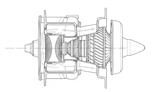
Gas Turbines
Gas turbines are internal combustion turbomachines that convert energy in gaseous working fluid into mechanical power. They consist of a compressor, combustor and turbine mounted on one or more shafts.
Typical features:
- Working fluid: Air and combustion products of fuel.
- Compressor type: Axial, or axial-centrifugal in smaller units.
- Turbine type: Axial, often multi-stage.
- Applications: Aircraft propulsion, power plants, mechanical drive for compressors and pumps.
Representative ranges for industrial and aeroderivative gas turbines:
- Power output: From below 1 MW for small units to above 400 MW for large heavy-duty units.
- Compressor pressure ratio: Roughly 8–35 depending on design.
- Turbine inlet temperature: Often in the range of 1200–1600 °C for high-performance units (with extensive cooling).
Steam Turbines
Steam turbines are driven by expanding steam and are widely used for electricity generation and mechanical drive in thermal power plants and industrial facilities.
Characteristics:
- Working fluid: Water steam at varying pressure and temperature levels.
- Configuration: Impulse, reaction, or combined stages; single or multi-casing; condensing or back-pressure types.
- Operation: Connected to steam cycle including boiler/HRSG, condenser and feedwater systems.
Typical operating data for large utility steam turbines:
- Inlet steam pressures: About 12–25 MPa for advanced units.
- Inlet steam temperatures: Often around 540–600 °C for main and reheat steam.
- Power rating: From several MW for industrial units to over 1000 MW in large thermal power plants.
Hydraulic Turbines
Hydraulic turbines convert hydraulic head of water in dams and rivers into mechanical power for power generation.
Main types include:
- Pelton turbines (impulse): Used for high-head, low-flow schemes.
- Francis turbines (reaction): Used for medium-head applications.
- Kaplan/Propeller turbines (reaction): Used for low-head, high-flow systems.
Typical ranges:
- Heads: Roughly from under 10 m for low-head Kaplan units to several hundred meters for Pelton units.
- Power ratings: From less than 1 MW for small hydro to several hundred MW per unit for large installations.
Compressors
Compressors increase the pressure of gases and vapors. In turbomachinery, the two principal forms are axial and centrifugal compressors.
Axial Compressors
Axial compressors incrementally increase pressure by passing the gas through multiple stages of rotating and stationary blades where flow is predominantly parallel to the shaft.
Key aspects:
- High flow capacity suitable for gas turbines and large process applications.
- Stage pressure ratios typically about 1.1–1.3 per stage.
- Overall pressure ratio achieved by multiple stages arranged in series.
- Blade designs tailored to maintain acceptable Mach numbers and avoid flow separation.
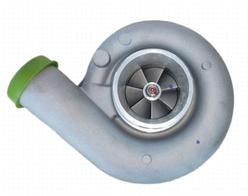
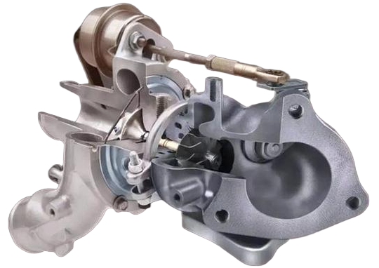
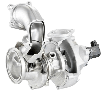
Centrifugal Compressors
Centrifugal compressors accelerate the gas radially outward through an impeller and diffuse it to convert kinetic energy into pressure rise.
Typical characteristics:
- Higher pressure rise per stage than axial compressors; single stage pressure ratios commonly in the range of 3–6.
- Compact design suitable for small to medium flows.
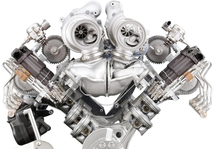
- Common use in process gas compression, small gas turbines, refrigeration and turbochargers.
Pumps
Pumps are power-absorbing turbomachines that transfer mechanical energy to liquids, primarily to increase their pressure and transport them through piping systems.
Primary types:
- Centrifugal pumps (radial and mixed-flow).
- Axial-flow pumps for high-flow, low-head applications.
Key parameters:
- Head (m of liquid): Measure of energy added to the fluid.
- Flow rate (m³/h or L/s): Capacity of the pump.
- Power input (kW): Hydraulic power divided by efficiency.
Fans and Blowers
Fans and blowers move air and other gases at relatively low pressure ratios compared with compressors.
Characteristics:
- Pressure ratios: Typically close to unity for fans, higher for blowers but usually below compressor ranges.
- Configurations: Axial and centrifugal types.
- Applications: HVAC, cooling of electrical equipment, process ventilation, combustion air supply.
Key Performance Parameters and Efficiencies
Turbomachinery performance is evaluated using thermodynamic and hydraulic parameters and various efficiencies that compare actual performance to idealized isentropic or inviscid behavior.
Power, Torque and Speed
Mechanical power on the shaft is given by:
P = T ω
where P is power, T is torque and ω is angular speed. In turbomachinery, rotational speeds may span from a few hundred revolutions per minute for large hydro turbines to several tens of thousands of revolutions per minute for small gas turbines and turbochargers.
Head, Pressure Ratio and Specific Work
Depending on machine type, performance may be expressed as:
- Head H (m) for pumps and hydraulic turbines.
- Pressure ratio π = pout / pin for compressors and fans.
- Specific work Ws (J/kg), often related to enthalpy change Δh.
In ideal isentropic processes, specific work can be linked to temperature or pressure ratios using thermodynamic relations for the working fluid.
Isentropic and Overall Efficiency
Isentropic efficiency measures how closely the process approaches an ideal isentropic process.
- For turbines:
ηis,t = (hin - hout,is) / (hin - hout,act) - For compressors:
ηis,c = (hout,is - hin) / (hout,act - hin)
Overall efficiency accounts for mechanical, volumetric and other losses between shaft and fluid or vice versa.
Specific Speed and Specific Diameter
Specific speed is a dimensionless or quasi-dimensionless parameter used to characterize turbomachines and guide selection for given duty points.
For pumps and hydraulic turbines, one common form of specific speed (in consistent units) is:
Ns = N √P / H5/4
where N is rotational speed, P is power and H is head. Various definitions exist depending on normalization. Specific speed gives an indication of appropriate machine type (radial, mixed, axial) for a particular flow and head requirement.
Performance Maps
Manufacturers and designers represent turbomachinery behavior using performance maps. These typically display:
- Flow versus head or pressure ratio.
- Efficiency contours.
- Operating limitations, such as surge line for compressors or cavitation limits for pumps.
These maps are essential for selecting and operating machines within stable and efficient regions.
Flow Physics and Loss Mechanisms
The performance of turbomachinery is influenced by detailed flow physics in blade passages, clearances and secondary flow regions.
Boundary Layers and Profile Losses
Fluid flows over blades in each rotor and stator row, forming boundary layers that grow in thickness and may separate if adverse pressure gradients are too strong. Profile losses arise from viscous dissipation in these boundary layers and wake mixing downstream of the blade trailing edge.
Secondary Flows and Tip Clearances
Three-dimensional flow phenomena occur near endwalls and blade tips, including:
- Secondary flows driven by pressure gradients and Coriolis effects.
- Tip leakage flows through clearances between blade tips and casing or hub.
- Vortex structures that contribute to additional loss and non-uniform exit flow.
To maintain efficiency, clearances are kept as small as practicable, and endwall contours and blade designs are optimized for reduced secondary loss.
Incidence, Deviation and Stall
When operating away from design conditions, flow angles at rotor and stator inlets deviate from design values, causing incidence. Excessive incidence may lead to flow separation, stall and, in compressors, surge. In fans and axial compressors, stall and surge can severely limit operating range and require careful matching of components and control strategies.
Cavitation in Hydraulic Machines
In hydraulic turbines and pumps, local static pressure may drop below vapor pressure of the liquid, causing cavitation. This can result in:
- Efficiency losses due to flow disturbances and vapor bubbles.
- Material damage from bubble collapse near solid surfaces.
Cavitation risk is evaluated using net positive suction head (NPSH) in pumps and cavitation coefficients in turbines, and mitigated via proper design of inlet conditions, blade geometries and installation layouts.
Design Considerations in Turbomachinery
Turbomachinery design requires simultaneous consideration of aerodynamics or hydrodynamics, thermodynamics, structural mechanics, rotor dynamics, materials and manufacturability.
Thermodynamic and Hydraulic Design
Design begins with specification of duty requirements: flow rate, head or pressure ratio, power and boundary conditions (inlet and outlet states). From these, stage loading, flow coefficients and number of stages are determined, followed by detailed design of blade rows.
Key design parameters include:
- Flow coefficient (ratio of meridional velocity to blade speed).
- Stage loading coefficient (related to specific work and blade speed).
- Reaction degree (fraction of stage enthalpy change occurring in rotor).
Design charts, non-dimensional parameters and numerical simulations are employed to achieve required performance within constraints of efficiency and operating range.
Blade Aerodynamics and Hydrodynamics
Blade profiles are designed to control velocity distributions, delay separation and minimize losses. In axial machines, cascades of airfoils or hydrofoils are arranged with specific pitch, chord and stagger to meet flow turning and loading requirements.
Important factors:
- Lift and drag behavior of blade sections at relevant Reynolds and Mach numbers.
- Blade thickness and camber distributions for structural strength and flow control.
- 3D shaping (twist, lean, sweep) for reduction of secondary loss and control of radial loading.
Structural Design and Rotor Dynamics
Rotating components are subject to high centrifugal and bending stresses. Structural design must ensure sufficient safety margins under operating conditions and transient events such as start-up and shutdown.
Key topics include:
- Stress analysis of blades, disks, rotors and casings.
- Fatigue life prediction under cyclic loading.
- Rotor dynamic analysis to avoid critical speeds and instability.
Clearances, bearings, seals and couplings are designed to maintain alignment, manage thermal growth and limit vibrations.
Materials Selection
Materials for turbomachinery must withstand mechanical loads, temperature, corrosion and erosion. Typical choices include:
- Steels and high-strength alloy steels for shafts and disks.
- Nickel-based superalloys for high-temperature gas turbine blades and vanes.
- Stainless steels for steam and hydraulic turbines where corrosion resistance is required.
- Titanium alloys in compressor blades and fan blades for high strength-to-weight ratio and corrosion resistance.
Material properties, including strength, creep resistance, fracture toughness and fatigue behavior, dictate allowable operating conditions and expected service life.
Core Components of Turbomachinery
Several component types are common across most turbomachines, differing in form and specifics according to working fluid and application.
Rotors and Shafts
Rotors carry the blades and transmit torque between turbomachine and driven equipment or generator. They are typically forged, machined and heat-treated to achieve required strength and dimensional stability.
Design aspects:
- Sectional design to distribute stress and accommodate disks or drums.
- Balancing provisions to minimize vibrations.
- Interfaces with couplings, bearings and seals.
Blades and Buckets
Blades (in compressors, fans and pumps) and buckets (in many turbines) are the primary elements that interact with the fluid. Their shape, surface quality and alignment strongly influence performance and reliability.
Characteristics:
- Variable cross-section with chord, thickness and twist optimized for flow and stress.
- Leading and trailing edges designed for controlled acceleration and diffusion of flow.
- In gas turbines, internal cooling passages and protective coatings for high-temperature operation.
Casings and Diffusers
Casings contain the flow and maintain structural integrity under pressure loads. Diffusers convert kinetic energy into pressure rise by slowing the fluid in gradually expanding passages.
Important considerations:
- Casing stiffness to control clearances and maintain rotor alignment.
- Diffuser angles designed to avoid boundary layer separation.
- Provision of access ports, instrumentation points and mounting features.
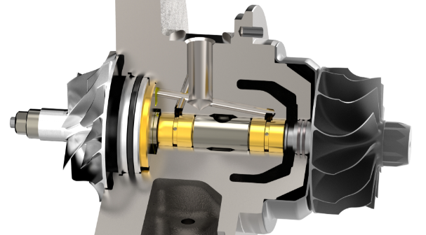
Bearings, Seals and Auxiliary Systems
Bearing systems support the rotor and allow it to rotate with low friction. Seals limit leakage between high and low pressure regions and control secondary flows.
Auxiliary systems may include lubrication systems, sealing gas or water systems, cooling systems and control systems for operation and protection.
Machining and Manufacturing of Turbomachinery
Manufacturing turbomachinery components demands high dimensional accuracy, surface quality and material integrity. Machining is a central part of the production chain, particularly for rotors, disks, blades and casings.
Machining Requirements and Considerations
Turbomachinery components must satisfy specific machining-related requirements:
- Geometric tolerances for concentricity, flatness and run-out on shafts and disks.
- Blade profile accuracy to maintain aerodynamic/hydrodynamic performance.
- Surface roughness levels compatible with efficiency and fatigue life requirements.
- Dimensional stability under operating temperatures and stresses.
Material machinability varies widely, especially for high-strength steels and nickel-based superalloys used in hot sections of gas turbines. Cutting tool selection, cutting parameters, coolant application and process sequence must be matched to material and geometry.
Rotor and Disk Machining
Rotors and disks are usually manufactured from forged blanks that are subsequently rough-machined, heat-treated and finish-machined.
Typical operations include:
- Turning of external and internal diameters, shoulders and journals.
- Drilling and boring of center holes and internal bores.
- Milling of keyways, slots and features for blade attachment (e.g., fir-tree or dovetail slots).
- Grinding for critical surfaces requiring tight tolerances and fine surface finishes.
For large rotors, specialized heavy-duty lathes and multi-axis machining centers are used. Final balancing is carried out using high-precision balancing machines to meet dynamic balance requirements that correspond to specified vibration limits.
Blade and Impeller Machining
Blades and impellers have complex three-dimensional geometries. Manufacturing approaches depend on material, size and required precision.
Common steps:
- Blade root and platform machining on prismatic or forging blanks.
- CNC milling or grinding of airfoil or hydrofoil profiles.
- Drilling of cooling holes in gas turbine blades using conventional drilling, EDM (electrical discharge machining) or laser machining.
- Edge finishing and polishing where necessary for surface quality.
For integrally bladed rotors (IBR) or blisks, blades and disks are machined from a single forging or billet, requiring multi-axis CNC machining. This minimizes assembly requirements and reduces weight but increases complexity of machining and repair processes.
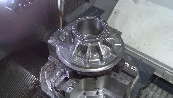
Casing and Housing Machining
Casings must achieve accurate fit with rotating components, maintain specified clearances and provide sealing surfaces. They are generally manufactured from cast or forged materials, followed by extensive machining.
Typical machining operations:
- Boring of internal diameters and steps to accommodate stator blade carriers, diffusers and seals.
- Milling of mounting faces, flanges and bolt patterns.
- Machining of grooves for seal rings and O-ring seats.
- Drilling and tapping for instrumentation ports, inspection openings and connections.
Large casings may be split horizontally or vertically. Both halves must be machined so that, when assembled, misalignment and clearance variations are within specified tolerances.
Surface Finishing and Tolerances
Surface finish is important both for fluid dynamic performance and fatigue life. Typical parameters include average surface roughness (Ra) and waviness.
Representative finish requirements (indicative ranges; exact specifications are application-dependent):
- Blades and impeller flow surfaces: Ra often within a fine range to minimize profile losses.
- Shaft journals and bearing surfaces: Very fine Ra values to ensure adequate lubrication and low wear.
- Sealing surfaces: Finish compatible with seal type to maintain leakage performance.
Tolerances on critical dimensions (e.g., blade angles, chord lengths, radii, disk diameters, shaft run-out) are established from performance and stress analyses and verified using coordinate measuring machines (CMM) and other inspection tools.
Manufacturing Processes Beyond Machining
In addition to machining, several other manufacturing processes are involved in producing turbomachinery components and assemblies.
Forging and Casting
Forging and casting are used to produce initial component forms with efficient material usage and favorable microstructures.
- Open-die or closed-die forging for shafts, disks and some blade blanks.
- Investment casting for complex blade geometries, especially in high-temperature gas turbine blades with internal cooling passages.
- Sand casting or other casting methods for casings and large volutes.
Subsequent heat treatments adjust mechanical properties such as strength, ductility and toughness to required values prior to final machining.
Joining and Assembly
Assembly involves joining rotors and casings with blades, vanes, seals, bearings and auxiliary systems. Joining methods can include:
- Mechanical fastening with dovetail or fir-tree blade roots and disk slots.
- Shrink fitting of rings and components using controlled temperature differences.
- Welding or brazing for certain attachments and fabricated components.
During assembly, clearances, alignment and concentricity are carefully controlled. For multi-stage machines, matching of components to achieve intended flow path and stage-to-stage alignment is critical.
Coatings and Surface Treatments
Coatings are applied to improve heat resistance, corrosion resistance, erosion resistance and friction behavior.
Examples:
- Thermal barrier coatings on gas turbine blades and vanes.
- Anti-corrosion and erosion-resistant coatings on steam turbine and hydraulic turbine components in aggressive environments.
- Surface treatments such as shot peening to enhance fatigue strength of blades and critical structural parts.
Quality Control, Testing and Commissioning
Quality control ensures that designed performance and reliability are achieved in manufactured turbomachinery.
Inspection and Non-Destructive Testing
Inspection methods include:
- Dimensional inspection with CMMs, gauges and alignment tools.
- Non-destructive testing (NDT) such as ultrasonic testing, radiography, magnetic particle inspection and dye penetrant inspection for detection of internal and surface defects.
- Hardness and microstructure evaluation for material verification.
Critical parts such as turbine blades, disks and rotors undergo stringent inspection criteria due to their high consequence in service.
Balancing and Run-Up Testing
Rotors are balanced in dedicated machines at specified speeds to control residual unbalance. During factory tests and commissioning:
- Vibration levels are measured and compared with allowable limits.
- Temperatures, pressures, flows and shaft displacements are monitored.
- Machine characteristics are checked against predicted performance curves.
Acceptance testing typically includes measurement of power, efficiency, flow, head or pressure ratio at defined operating points and verification of protection and control system functionality.
Installation, Operation and Maintenance Considerations
Successful operation of turbomachinery depends not only on design and manufacturing but also on proper installation, operation and maintenance practices.
Installation and Alignment
Installation requires foundations and supports that provide sufficient rigidity and stability. Alignment procedures ensure correct relative positions of shafts, couplings and driven equipment.
Key aspects:
- Baseplate leveling and anchor bolt tensioning.
- Shaft alignment using dial indicators or laser alignment systems.
- Verification of clearances and coupling fits.
Operating Conditions and Monitoring
Operating conditions such as load, speed, inlet temperature, pressure and fluid quality influence performance and life. Continuous or periodic monitoring of critical parameters helps maintain machines within specified operating envelopes.
Typical monitored variables:
- Vibration amplitude and phase at bearings and casings.
- Bearing and winding temperatures, where applicable.
- Lubrication system pressure and temperature.
- Fluid properties such as water purity in steam cycles and gas composition in process compressors.
Maintenance and Overhauls
Maintenance strategies range from scheduled periodic inspections to condition-based maintenance based on measured operating data.
Routine tasks may include:
- Lubrication system checks and oil replacement.
- Filter and strainer cleaning or replacement.
- Inspection of seals, bearings and couplings.
Major overhauls involve disassembly, inspection and replacement or repair of blades, rotors, casings, seals and bearings, followed by reassembly, alignment, balancing and testing.

Typical Engineering Pain Points in Turbomachinery Projects
Engineering teams dealing with turbomachinery often encounter specific difficulties related to design, manufacturing and operation. Some representative pain points include:
- Maintaining tight blade and tip clearances to achieve efficiency targets while allowing for thermal expansion and rotor dynamics.
- Machining and inspecting complex three-dimensional blade geometries in high-strength, difficult-to-machine alloys while meeting surface finish and profile tolerances.
- Integrating rotor, bearing and casing designs to control vibration and avoid resonance at operating and transient speeds.
- Achieving required performance under varying operating conditions without exceeding surge limits (compressors) or cavitation limits (pumps and hydraulic turbines).
- Coordinating design for manufacturability, maintainability and performance so that components can be produced and serviced without excessive cost or downtime.
Addressing these challenges requires close collaboration between design, analysis, manufacturing and field service teams, as well as rigorous adherence to validated procedures and standards.
FAQ About Turbomachinery
What is the difference between a pump, a compressor and a turbine?
Pumps, compressors and turbines are all turbomachines but they differ in function and fluid state. A pump adds energy to a liquid, usually treated as incompressible, to increase its pressure and move it through a system. A compressor adds energy to a gas, significantly increasing its pressure and often its temperature; compressibility effects are important. A turbine extracts energy from a moving fluid, whether gas, steam or liquid, converting it into mechanical power on a shaft that can drive a generator or other equipment.
Why is machining accuracy so critical in turbomachinery components?
Machining accuracy is critical because performance and reliability of turbomachinery depend on precise blade profiles, tight clearances and correct rotor geometry. Small deviations in blade angle or surface finish can increase aerodynamic or hydraulic losses, reducing efficiency. Excessive run-out or imbalance in rotors can cause high vibration, accelerating wear and increasing the risk of fatigue failures. Tight control of tolerances and surface quality during machining helps ensure that the machine operates as designed, meets specified efficiency and remains within acceptable vibration and stress limits throughout its service life.
What causes cavitation in pumps and hydraulic turbines?
Cavitation occurs when local static pressure in the liquid drops below its vapor pressure, leading to formation of vapor bubbles. As these bubbles move to regions of higher pressure, they collapse and can generate high local stresses on surfaces. In pumps and hydraulic turbines, cavitation is often caused by insufficient net positive suction head (NPSH), excessive flow velocities, abrupt changes in geometry or operating beyond the recommended range. It can lead to performance loss, noise, vibration and material damage on blades and other wetted components.
How are gas turbine blades protected from high temperatures?
Gas turbine blades in high-temperature stages are protected through a combination of material selection, internal cooling and coatings. They are commonly made from nickel-based superalloys with high creep and fatigue strength at elevated temperatures. Internal cooling passages carry cooler air through the blade, and film cooling holes eject air to form a protective layer on the surface. Thermal barrier coatings applied to the blade surface reduce heat transfer into the metal and provide oxidation and corrosion resistance. Together, these measures allow blades to operate in environments where gas temperatures exceed the allowable metal temperatures.
