
CNC turning and CNC milling are two fundamental subtractive machining processes used to manufacture precise metal and plastic components. While both are controlled by computer numerical control (CNC) and remove material from a solid workpiece, they differ significantly in the way motion is generated, the type of tools used, and the shapes they produce. Understanding these differences is essential for engineers, machinists, buyers, and product designers who must choose the most suitable process for each part.
Basic Definitions and Core Concept
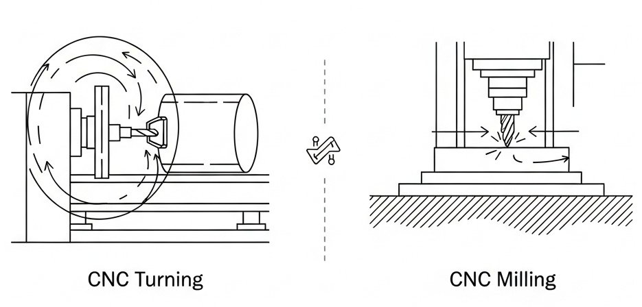
CNC turning and CNC milling can be distinguished most easily by identifying which element rotates and which remains stationary during cutting.
- CNC turning: the workpiece rotates, and the cutting tool is generally stationary in rotation but moves linearly.
- CNC milling: the cutting tool rotates, and the workpiece is generally stationary in rotation but moves linearly (or in multiple axes).
Both processes are executed on CNC machine tools that follow programmed toolpaths, feed rates, and spindle speeds. These programmed instructions are usually written in G-code or generated automatically by CAM (Computer-Aided Manufacturing) software based on a CAD (Computer-Aided Design) model.
How CNC Turning Works
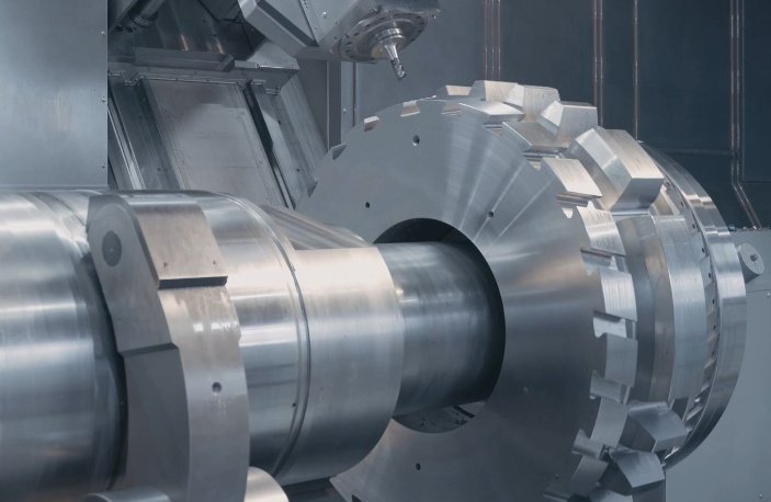
CNC turning is performed on a CNC lathe or turning center. It is particularly suited for manufacturing rotationally symmetric parts with circular cross-sections.
1. Working Principle of CNC Turning
In CNC turning:
- The workpiece is clamped in a chuck or collet and rotated by the spindle.
- Single-point or limited-multi-point cutting tools are mounted on a turret or tool post.
- The tools move along linear axes (typically X and Z) to remove material and create external or internal features.
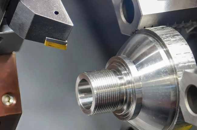
Common turning operations include:
- Facing: creating a flat surface at the end of the workpiece.
- Straight turning: reducing the diameter to a specified size.
- Taper turning: producing a conical surface along the length.
- Grooving: cutting narrow channels on external or internal surfaces.
- Parting (cut-off): separating the finished part from the bar stock.
- Boring: enlarging and finishing internal diameters.
- Threading: forming internal or external threads.
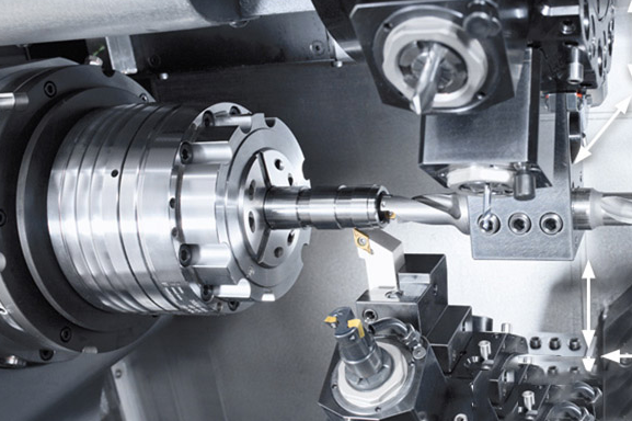
2. Typical CNC Turning Machine Configuration
A CNC turning center usually includes:
- Headstock with spindle and chuck/collet system.
- Tailstock (for supporting long workpieces when needed).
- Turret or tool post with multiple indexed tools.
- Bed and carriage for supporting and moving the tool assembly.
- CNC control panel for programming and operation.
More advanced turning centers can be equipped with:
- Sub-spindle for back-side machining.
- Y-axis for limited milling operations on the lathe.
- Live tooling (rotating tools) for drilling and light milling operations.
3. Workpiece Types and Suitable Shapes for Turning
CNC turning is ideal for parts with:
- Cylindrical or conical outer surfaces.
- Axial symmetry about a central axis.
- Internal bores aligned with the rotation axis.
Typical example parts include shafts, pins, bushings, flanges, pulleys, sleeves, and threaded components.
4. Technical Characteristics of CNC Turning
Some technical attributes of CNC turning (typical values, may vary by machine and setup):
- Spindle speed range: approximately 50–5,000 rpm or higher, depending on machine.
- Feed rate: typically 0.05–0.5 mm/rev for finishing, 0.1–0.7 mm/rev for roughing (material-dependent).
- Tolerances: IT6–IT9 possible with appropriate tooling and conditions (e.g., ±0.01 mm to ±0.05 mm) for many materials.
- Surface roughness: Ra 0.8–3.2 µm common, Ra 0.4 µm or better possible with fine turning and good conditions.
How CNC Milling Works
CNC milling is performed on a CNC milling machine or machining center. It is well-suited for parts with flat surfaces, pockets, slots, complex 3D surfaces, and non-rotational geometries.
1. Working Principle of CNC Milling
In CNC milling:
- The cutting tool rotates at high speed.
- The workpiece is fixed on a table or fixture.
- The tool moves relative to the workpiece along multiple axes (commonly X, Y, and Z, and optionally A, B, C rotational axes).
Common milling operations include:
- Face milling: creating a flat surface with a large-diameter cutter.
- End milling: slotting, profiling, and contouring using end mills.
- Pocketing: creating internal cavities of various shapes.
- Drilling and tapping: forming holes and internal threads.
- 3D contouring: machining complex free-form surfaces.
2. Typical CNC Milling Machine Configuration
A typical CNC milling machine or machining center includes:
- Spindle for holding rotating tools.
- Worktable or pallet for clamping the workpiece.
- Linear axes (usually X, Y, Z) and possibly rotational axes (A, B, C).
- Automatic tool changer (ATC) with magazine or carousel for multiple tools.
- CNC control for programming and operation.
Variants of CNC milling machines include:
- Vertical machining centers (VMC) with a vertical spindle.
- Horizontal machining centers (HMC) with a horizontal spindle.
- Multi-axis machining centers (4-axis, 5-axis) that can tilt or rotate the workpiece or spindle.
3. Workpiece Types and Suitable Shapes for Milling
CNC milling is ideal for parts with:
- Complex prismatic shapes.
- Flat surfaces, inclined planes, and slots.
- Pockets, cavities, and ribs.
- Complex 3D surfaces and free-form shapes.
Typical example parts include housings, plates, brackets, molds, dies, manifolds, and structural components.
4. Technical Characteristics of CNC Milling
Some typical technical parameters for CNC milling (values depend on machine, material, tool, and application):
- Spindle speed range: roughly 500–20,000 rpm; high-speed spindles can exceed 30,000 rpm.
- Feed rate: from tens to several thousands of mm/min, depending on operation and tool.
- Tolerances: IT6–IT9 commonly achievable (e.g., ±0.01 mm to ±0.05 mm); tighter tolerances possible with precision setups.
- Surface roughness: Ra 0.8–3.2 µm typical for standard finishing; Ra 0.4 µm or better achievable in high-quality finishing operations.

Key Differences Between CNC Turning and CNC Milling
The fundamental differences between CNC turning and CNC milling can be summarized based on motion, geometry, tooling, productivity, and part characteristics.
| Aspect | CNC Turning | CNC Milling |
|---|---|---|
| Primary motion | Workpiece rotates, tool feeds linearly | Tool rotates, workpiece usually stationary (linear moves) |
| Typical part shape | Rotationally symmetric, cylindrical parts | Prismatic and complex 3D shapes |
| Machine type | Lathe / turning center | Milling machine / machining center |
| Typical operations | Facing, turning, boring, threading, grooving | Face milling, end milling, pocketing, drilling |
| Tooling | Mainly single-point tools, inserts | Multi-flute rotating cutters (end mills, face mills, drills) |
| Best suited for | Shafts, pins, bushings, threaded parts | Housings, plates, molds, brackets, complex surfaces |
| Material removal pattern | Continuous cuts along rotating surface | Interrupted cuts via rotating tool teeth |
| Fixture complexity | Usually simpler (chuck/collet) | Often more complex fixturing for irregular parts |
| Typical batch suitability | Very efficient for medium to high volumes of turned parts | Suited for prototypes, small to large batches of milled parts |
Tooling Differences
Tooling is a major factor defining capabilities, costs, and surface quality in both processes.
1. CNC Turning Tools
Turning operations mainly use single-point tools or indexable inserts. Common tool types include:
- External turning tools (right-hand and left-hand) for OD turning.
- Internal boring bars for ID machining.
- Parting and grooving tools.
- Threading tools for internal and external threads.
- Form tools for special profiles.
Typical features of turning tools:
- Tool materials: carbide, cermet, high-speed steel (HSS), ceramics, cubic boron nitride (CBN), polycrystalline diamond (PCD).
- Replaceable inserts with different geometries (nose radius, rake angle, chip breaker) optimized for various materials and operations.
2. CNC Milling Tools
Milling relies on rotating multi-edge tools. Common milling tools include:
- End mills (square, ball nose, corner radius).
- Face mills for high-efficiency surface machining.
- Slot drills and keyway cutters.
- Drills, reamers, and taps used via the milling machine spindle.
- Form cutters and special 3D profile cutters.
Typical characteristics of milling tools:
- Multiple cutting edges (flutes) for higher material removal rate.
- Varied helix angles and flute geometries tailored to materials (e.g., aluminum, steel, titanium, plastics).
- Coatings for wear resistance and heat management (e.g., TiN, TiAlN, AlTiN, DLC).
Machine Structure and Axis Configuration
Machine design and axis configuration strongly influence the type and complexity of machining operations possible.
1. Axis Configuration in CNC Lathes
Basic CNC lathes typically feature:
- Z-axis: along spindle centerline (longitudinal feed).
- X-axis: radial direction (diameter control).
More advanced turning centers may include:
- Y-axis: for off-center milling, drilling, and complex features.
- C-axis: spindle indexing or continuous rotation under CNC control for live-tool operations.
- Sub-spindle: additional spindle to allow secondary operations on the back side of parts.
2. Axis Configuration in CNC Milling Machines
Standard machining centers usually offer:
- X-axis: left-right table movement.
- Y-axis: front-back movement.
- Z-axis: up-down spindle or table movement.
Advanced machines can include additional rotational axes for multi-axis machining:
- 4-axis: typically one rotary axis (A, B, or C) added to the three linear axes.
- 5-axis: two rotary axes in addition to three linear axes, allowing complex orientation of the tool relative to the workpiece.
Multi-axis milling allows machining of multiple faces and complex surfaces in a single setup, improving accuracy and reducing handling time.
Materials and Workpiece Size Considerations
Both CNC turning and CNC milling can handle a wide range of materials, but there are practical differences regarding workpiece size, shape, and clamping.
1. Materials
Common materials for both processes include:
- Metals: carbon steel, alloy steel, stainless steel, aluminum, copper, brass, bronze, titanium, nickel alloys.
- Plastics: ABS, nylon, POM, PEEK, PTFE, polycarbonate, acrylic.
- Others: some composites and ceramics (with specific tools and setups).
Turning often handles bar stock, tube, and pre-formed blanks, while milling frequently uses plate, blocks, or castings.
2. Workpiece Size and Shape
In CNC turning:
- Workpiece diameter and length are constrained by chuck size, spindle bore, and machine bed length.
- Long slender parts may require tailstock or steady rests to control deflection.
In CNC milling:
- Maximum workpiece size is limited by table travel (X, Y) and clearance in Z.
- Large flat or block-shaped components are often easier to fixture for milling than for turning.
Dimensional Accuracy and Surface Finish
CNC turning and CNC milling can both achieve high accuracy and good surface finish, but performance differs depending on geometry and setup.
1. Dimensional Accuracy
Turning often provides slightly better roundness and concentricity for cylindrical features because the workpiece is rotated about a fixed axis. Milling offers high accuracy on planar and prismatic surfaces when properly fixtured.
- Turning: highly accurate diameters and concentric features due to single-axis rotation; roundness can be within a few micrometers on precision machines.
- Milling: very precise planar dimensions and hole locations achievable, especially with high-quality fixtures and measuring systems.
2. Surface Finish
Surface roughness is influenced by tool geometry, cutting speed, feed rate, depth of cut, workpiece material, and machine rigidity.
Typical surface finish ranges (approximate):
- CNC turning: Ra ≈ 0.4–3.2 µm for finishing; roughing may be higher.
- CNC milling: Ra ≈ 0.8–3.2 µm for finishing; fine milling and polishing can reduce Ra further.
Turning usually generates spiral tool marks along the rotational direction, while milling produces feed marks in the direction of tool travel.
Production Efficiency and Cost Factors
Cost and productivity are essential considerations when choosing between CNC turning and CNC milling. These are influenced by cycle time, tool costs, machine hourly rates, and setup complexity.
1. Cycle Time and Material Removal Rate
In turning, continuous engagement of a single-point tool on a rotating workpiece can provide efficient material removal for cylindrical parts. In milling, multi-edge tools can also remove material quickly, especially with advanced toolpaths and multiple flutes.
Turning is generally more time-efficient for parts where the majority of material removal is on external or internal cylindrical surfaces. Milling becomes more efficient for parts with multiple faces, pockets, and complex shapes.
2. Setup and Fixturing Cost
Setup time strongly affects cost, particularly for low-volume production.
- CNC turning: fixturing often involves mounting in a chuck, collet, or mandrel. Setup tends to be relatively straightforward for standard round stock.
- CNC milling: fixturing may require dedicated jigs, vises, clamps, or vacuum fixtures, especially for complex shapes. Setup time can be higher for irregular parts.
For high-volume production, dedicated fixtures and optimized setups can significantly reduce cycle time per part in both turning and milling.
3. Tooling and Maintenance Cost
Turning and milling both involve ongoing tooling costs (inserts, cutters, drills, etc.). Tool life depends on cutting parameters, workpiece material, cooling, and machine rigidity.
- Turning: indexable inserts are frequently replaced but are quick to change, minimizing downtime.
- Milling: more tool types and sizes may be required for one part (e.g., roughing end mill, finishing end mill, drills), but automatic tool changers streamline tool changes.
Machine maintenance costs depend on complexity: sophisticated multi-axis machining centers and multi-tasking machines generally require higher investment and maintenance compared to basic lathes or mills.
Typical Applications of CNC Turning
CNC turning is preferred in applications where rotational symmetry and precise diameters are critical.
1. Mechanical Shafts and Rotating Components
Examples:
- Motor shafts and drive shafts.
- Axles and spindles.
- Rollers and sleeves.
Such parts often require tight tolerances on diameter, roundness, and surface finish to ensure correct fit with bearings and seals.
2. Fasteners and Threaded Components
CNC turning is widely used to manufacture threaded rods, bolts, nuts (when rotational), and various connectors. Internal and external thread profiles can be machined with high consistency, including metric, imperial, and special thread forms.
3. Fittings, Bushings, and Couplings
Turning is suitable for producing bushings, pipe fittings, flanges, couplings, and other circular components used in fluid systems, machinery, and structural assemblies.
Typical Applications of CNC Milling
CNC milling is applied to parts with complex surfaces, multi-sided features, and non-rotational geometries.
1. Precision Plates and Structural Components
Examples include machine base plates, brackets, and frames with multiple holes, slots, and pockets. Milling provides precise perpendicularity and flatness for these components.
2. Mold and Die Components
Mold cavities, die inserts, and tool components often feature intricate 3D surfaces that require multi-axis milling. Milling can accurately reproduce free-form shapes defined by CAD data, which is essential for plastic injection molds, die casting tools, and forging dies.
3. Housings and Enclosures
Complex housings for pumps, transmissions, gearboxes, and electronic enclosures often require milling for their internal and external features, including bores, pockets, ribs, sealing surfaces, and mounting flanges.

Combined Machining: When Turning and Milling Are Used Together
Many parts feature both rotational and non-rotational elements and may require both CNC turning and CNC milling.
1. Sequential Processing on Separate Machines
In many workshops, a part may go through turning first to create cylindrical features, and then be transferred to a milling machine for flats, keyways, holes, or other features.
Example:
- Turned shaft with milled keyways, flats for wrench grips, or drilled and tapped holes at specific angular positions.
2. Multi-Tasking Machines (Turn-Mill Centers)
Turn-mill centers combine turning and milling capabilities in one machine. While this article focuses on the distinction between turning and milling as processes, multi-tasking machines perform both by integrating live tooling and additional axes on a turning platform, or vice versa.
Advantages of combined machining for suitable parts:
- Reduced number of setups and machine transfers.
- Improved positional accuracy between turned and milled features.
- Shorter overall throughput time.
Selection Guidelines: When to Choose Turning or Milling
Selecting between CNC turning and CNC milling depends on geometry, tolerance requirements, volume, and manufacturing resources. The following guidelines provide a systematic way to choose.
1. Geometry-Based Decision
Choose CNC turning if:
- The part is rotationally symmetric around a central axis.
- The main features are diameters, tapers, grooves, and threads along the length.
- Any non-cylindrical features are minimal or can be avoided.
Choose CNC milling if:
- The part has multiple flat faces, pockets, slots, or complex 3D surfaces.
- Features are located on different planes and orientations.
- The part shape is not primarily cylindrical.
2. Tolerance and Surface Requirements
Choose turning when:
- Tight tolerances on diameters and concentricity are critical.
- Superior roundness and cylindricity are required.
Choose milling when:
- Precise planar relationships, hole patterns, and positional tolerances are important.
- Complex 3D profiles must match CAD-defined surfaces.
3. Volume and Cost Considerations
For large volumes:
- Turning is very efficient for high-volume production of shafts, bushings, and similar parts, especially from bar stock.
- Milling remains suitable for high volumes when parts have complex shapes that cannot be turned; dedicated fixtures and optimized toolpaths are key.
For low volumes or prototypes:
- Both processes are suitable; selection is mainly based on geometry rather than volume.
- For one-off or small series, minimizing setup complexity and using versatile machines can reduce cost.
Design Considerations for Turning vs. Milling
When designing parts that will be manufactured by CNC turning or CNC milling, understanding process capabilities helps improve manufacturability and reduce cost.
1. Design for CNC Turning
Recommended practices:
- Use uniform diameters and avoid unnecessary steps when possible.
- Optimize fillet radii and chamfers to match standard tool nose radii and insert geometry.
- Keep deep grooves and undercuts within tool reach and standard widths when possible.
- Consider bar stock availability and dimensions to minimize waste.
2. Design for CNC Milling
Recommended practices:
- Use standard hole sizes and thread dimensions whenever possible.
- Apply reasonable wall thickness to avoid vibration and deflection during milling.
- Ensure tool access to deep pockets and complex features; consider draft angles or reliefs.
- Minimize unnecessary complex surfaces that increase toolpath time and programming effort.
Comparison of Common Use Cases
The following table summarizes typical use cases to clarify when a designer or process engineer might select CNC turning or CNC milling.
| Part / Requirement | Preferred Process | Reason |
|---|---|---|
| Long shaft with multiple diameters and threads | Turning | Rotational symmetry, efficient diameter and thread machining |
| Flat plate with hole pattern and pockets | Milling | Planar surfaces, multi-axis hole locations, pockets |
| Bushing with precise inner and outer diameters | Turning | Accurate diameters and concentricity via lathe |
| Complex 3D mold cavity | Milling | Multi-axis contouring for free-form surfaces |
| Shaft with keyway and side flats | Turning + Milling | Turning for main diameter, milling for flats/keyway |
Common Issues and Practical Considerations
In real production environments, several practical issues may influence the choice between CNC turning and CNC milling or affect the machining results.
1. Workpiece Rigidity and Deflection
For long, slender components, turning operations can be affected by deflection, vibration, and chatter. Supporting the part with a tailstock, steady rest, or follow rest is often necessary. In milling, thin walls and narrow ribs are susceptible to vibration; adjustments in toolpath, step-over, and clamping strategy help control deflection.
2. Chip Evacuation
Both processes generate chips that must be evacuated efficiently to avoid surface damage, tool wear, and machine downtime.
- Turning: continuous chips often appear when cutting ductile metals; chip breakers on inserts and appropriate feed control are essential.
- Milling: chips are usually shorter and easier to evacuate, but deep pockets and blind holes require suitable toolpaths and coolant flow.
3. Heat and Tool Wear
Heat generation is inherent in cutting processes. Adequate cooling (flood coolant, minimum quantity lubrication, or air blast) and correct cutting parameters help manage tool wear and maintain consistent tolerances. Hard materials and high cutting speeds increase wear in both turning and milling.
Summary
CNC turning and CNC milling are both essential machining processes, each optimized for specific types of geometry and production conditions. Turning excels at producing precise cylindrical components with high efficiency and excellent roundness, while milling is dominant for prismatic and complex 3D shapes, multi-face machining, and intricate surface features. Understanding how each process works, their tooling and machine configurations, and their typical applications allows engineers, machinists, and buyers to select the most appropriate method for each part, optimize cost, and achieve required performance and quality.
CNC Turning vs CNC Milling: XCM Helps You Choose the Right Process
At XCM, we don’t just machine parts—we help you choose the most efficient process for your design and budget. With in-house CNC turning and CNC milling capabilities, including multi-axis lathes and 3/4/5-axis machining centers, our engineering team evaluates your part geometry, tolerances, and quantities to recommend the best approach. For round, shaft-like components, CNC turning delivers fast, cost-effective production with excellent concentricity; for prismatic parts with complex faces, pockets, and contours, CNC milling provides superior flexibility. By combining both processes under one roof, XCM optimizes cycle time, reduces setups, and lowers overall cost, ensuring you receive high-precision metal and plastic parts—machined the right way from prototype to production.
FAQ About CNC Turning and CNC Milling
Which is more accurate, CNC turning or CNC milling?
Both CNC turning and CNC milling can achieve high accuracy when properly set up. CNC turning typically provides superior roundness and concentricity for cylindrical features because the workpiece rotates around a fixed axis. CNC milling offers high accuracy for flat surfaces, hole locations, and prismatic features when the part is correctly fixtured. The actual accuracy achieved depends more on machine quality, tool condition, fixturing, and process control than on the process type alone.
Is CNC turning cheaper than CNC milling?
For parts that are primarily cylindrical, CNC turning is often more cost-effective than milling because material removal is efficient and fixturing is simpler. For non-cylindrical parts with multiple faces, pockets, and complex features, CNC milling is usually the only practical option even if the cycle time is longer. Overall cost depends on part geometry, batch size, setup time, machine hourly rate, and tool costs. Selecting the process that matches the part geometry generally leads to the lowest cost.
Can the same part be made by both turning and milling?
Some parts can be produced using either process, but usually with trade-offs. For example, a short cylindrical part might be turned from bar stock or milled from a block. However, turning will generally be more efficient and provide better roundness for cylindrical features, whereas milling may be more practical if the part requires extensive non-rotational features. Many complex components are best produced using a combination of turning and milling, either on separate machines or on a multi-tasking turn-mill center.
When should I use a turn-mill machine instead of separate turning and milling machines?
A turn-mill machine is advantageous when a part includes both significant cylindrical features and milled features, and when reducing setups and handling is important. Using a single turn-mill center can improve positional accuracy between features, shorten total lead time, and reduce work-in-progress. However, the investment cost and programming complexity are higher than for standalone machines. For simple parts or low volumes, separate turning and milling operations may be sufficient and more economical.
