
CNC turning is one of the most widely used manufacturing processes for making precise cylindrical parts such as shafts, bushings, fittings, and fasteners. For beginners, the terminology, machine components, and programming aspects can be confusing. This guide explains the CNC turning process in a structured, technical, and practical way, so you can understand how it works and how to use it effectively in production or product development.
What Is CNC Turning?
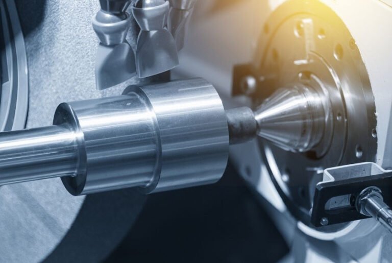
CNC turning is a CNC machining process in which a cutting tool removes material from a rotating workpiece using a computer-controlled lathe. CNC stands for Computer Numerical Control. The machine interprets a program containing coordinates and commands, then automatically controls the motion of the cutting tool and the rotation of the workpiece.
The main characteristics of CNC turning are:
- The workpiece rotates around its axis, held by a spindle (usually via a chuck or collet).
- A stationary or linearly moving cutting tool removes material to form the desired geometry.
- The process is ideal for producing parts that are axisymmetric (rotationally symmetric) and often long compared to their diameter.
CNC turning is used for both prototype quantities and large-volume production. It offers high dimensional accuracy, repeatability, and the ability to create complex profiles along the length of a part.

How CNC Turning Works: Process Overview
The CNC turning process can be broken down into a sequence of typical steps, from design to finished part. Understanding this sequence helps you plan projects, estimate lead time, and communicate with machine shops or internal manufacturing teams.
1. Part Design and CAD Modeling
The process usually starts with a 2D drawing or 3D CAD model of the part. The design should clearly indicate:
- All key dimensions (diameters, lengths, thread specifications, grooves, chamfers, radii).
- Tolerances for critical features, such as fits with mating parts.
- Surface finish requirements (e.g., Ra 1.6 μm, Ra 0.8 μm where necessary).
Well-prepared drawings minimize misunderstandings and reduce rework. Designers generally select turning for parts whose main features are cylindrical, such as stepped shafts, pins, and rings.
2. Process Planning and CAM Programming
After design, the part is analyzed by a manufacturing engineer or programmer. They determine:
- How the part will be held (chuck type, jaw configuration, clamping length).
- The sequence of operations (facing, rough turning, finish turning, grooving, threading, drilling, etc.).
- The tools required (turning inserts, boring bars, drills, threading tools).
CAM (Computer-Aided Manufacturing) software is often used to generate toolpaths and NC code (commonly in G-code format). Key settings defined in the program include:
- Spindle speed or surface speed (S value)
- Feed rate (F value)
- Depth of cut and number of passes
- Coolant on/off commands
- Tool change commands and offsets
3. Machine Setup
Before production, the operator prepares the CNC lathe:
- Loads the correct chuck or collet and sets up any required fixtures.
- Mounts tools in the turret or tool post and registers them in the tool library.
- Sets tool offsets and work coordinate system (e.g., G54) using probes or manual measurements.
- Loads the raw material (bar or blank) and checks clamping force and runout.
Accurate setup is critical. Misalignment or incorrect offsets can cause dimensional errors or collisions.
4. Trial Run and First Article Inspection
For a new part, the program is normally run in a controlled way:
- Dry run or single-block mode without cutting, to verify tool motion paths.
- First article manufactured with careful observation.
- Measurement of key dimensions using calipers, micrometers, or coordinate measuring machines (CMM).
Based on the results, minor adjustments to tool offsets, speeds, or feeds may be made to meet specifications and optimize cycle time.
5. Production Machining
Once the process is validated, the machine runs in production mode. The operator monitors:
- Tool wear and tool life (inserts may require periodic replacement).
- Chip formation and removal.
- Coolant levels, filter condition, and temperature.
- Random or scheduled inspections to ensure the process stays within tolerance.
Depending on the equipment, material bars can be automatically fed by a bar feeder, or pre-cut blanks can be manually loaded into the chuck.
6. Deburring, Cleaning, and Final Inspection
After turning, parts may undergo secondary steps:
- Deburring sharp edges by hand or using mechanical deburring tools.
- Washing to remove chips and machining fluid.
- Final inspection for dimensions and surface finish.
Parts that pass final inspection are then ready for downstream operations such as heat treatment, grinding, surface coating, or assembly.
Main Components of a CNC Lathe
Understanding the major components of a CNC lathe helps you interpret specifications and choose appropriate machines for specific tasks.
| Component | Function | Typical Considerations |
|---|---|---|
| Bed | Rigid base that supports all major elements and guides | Rigidity, vibration damping, maximum part length |
| Headstock | Houses the main spindle and drive system | Spindle power, maximum speed, spindle bore size |
| Spindle | Rotates the workpiece, often with chuck or collet | Speed range (rpm), spindle nose type, through-hole diameter |
| Chuck / Collet | Clamps and centers the workpiece | Clamping range, jaw type, gripping force, changeover time |
| Turret / Tool Post | Holds multiple tools and indexes them into position | Number of stations, tool size, indexing speed |
| Slides (X/Z axes) | Guide the movement of the cutting tool relative to the workpiece | Travel length, rapid traverse speed, ball screw accuracy |
| Tailstock (if present) | Supports long workpieces using a center | Maximum quill travel, center taper, clamping force |
| CNC Control | User interface and controller for motion and logic | Control brand, memory, supported functions, ease of programming |
| Coolant System | Provides cutting fluid to tool–workpiece interface | Pump pressure, flow rate, filtration, fluid compatibility |
| Chip Conveyor | Removes chips from the cutting area | Conveyor type, discharge height, chip type handling |
The combination of these components determines the capacity and capability of a given CNC turning center, such as maximum part diameter, achievable surface finish, and productivity.
Types of CNC Turning Machines
Different machine configurations are suited to different part types, volume levels, and complexity. Below are common categories of CNC turning machines.
1. Two-Axis CNC Lathes
These are the simplest CNC turning machines with X and Z linear axes. They perform operations such as facing, OD turning, ID boring, threading, and parting. They are widely used for standard cylindrical parts and are efficient for many production tasks.
2. CNC Turning Centers with Live Tooling
These machines add driven tools and often a C-axis spindle. They can perform limited milling, drilling, and tapping operations off the main turning axis, allowing features like flats, keyways, cross holes, and complex contours in a single setup.
3. Multi-Spindle and Multi-Turret Machines
Multi-spindle and multi-turret lathes allow multiple tools to cut simultaneously, often on different sections of the same part. This significantly reduces cycle time for high-volume parts, such as automotive or hydraulic components.
4. Swiss-Type CNC Lathes
Swiss-type lathes use a sliding headstock and guide bushing to support slender workpieces very close to the cutting area. They are used extensively for small-diameter, long parts requiring high precision, such as medical components, watch parts, and miniature shafts.
5. Vertical CNC Lathes
Vertical lathes orient the spindle vertically and are commonly used for large, heavy workpieces such as discs, rings, and large flanges. Gravity helps center heavy parts, and the vertical arrangement can simplify handling.
Core CNC Turning Operations
CNC turning encompasses various operations carried out with specific tools and toolpaths. The most common operations are described below.
1. Facing
Facing creates a flat surface perpendicular to the part’s axis by moving the tool radially across the end of the rotating workpiece. It is usually the first step to establish a reference face and a consistent part length.
2. Straight Turning and Step Turning
Straight turning reduces the diameter along the length of the part. Step turning creates multiple diameters with abrupt transitions, known as shoulders or steps. These steps may be used for seating bearings, seals, or other components.
3. Taper Turning
Taper turning produces conical surfaces. The tool moves in a path that gradually changes the radius as it moves along the length. Tapers are used for features like Morse tapers, pipe connections, and centering seats.
4. Profiling (Contouring)
Profiling uses a controlled toolpath to generate complex curves or non-linear profiles, such as fillets, grooves with varying radius, or ornamental shapes. CNC control allows precise repetition of these profiles across many parts.
5. Boring and Internal Turning
Boring enlarges or finishes an existing hole, often created by drilling. Internal turning operations can generate precise internal diameters, grooves, and threads in bores. Tools such as boring bars and internal grooving tools are used for this purpose.
6. Grooving and Parting-Off
Grooving cuts narrow channels on the outer or inner surface for O-rings, retaining rings, or lubrication paths. Parting-off (cut-off) uses a similar tool to separate the finished part from the bar or raw material.
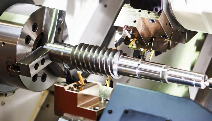
7. Threading
Threading produces helical grooves that form external or internal threads. CNC lathes synchronize the tool movement with spindle rotation to maintain the required pitch and thread profile. Both metric and imperial threads, as well as special forms, can be produced.
8. Drilling, Tapping, and Milling (on Turning Centers)
Turning centers equipped with live tooling can perform drilling and tapping operations along or perpendicular to the part axis. Limited milling operations (e.g., flats, slots) can also be done, reducing the need for separate machining centers and additional setups.

Key Process Parameters in CNC Turning
Process parameters directly affect cycle time, tool life, surface finish, and dimensional accuracy. When planning or evaluating a turning process, the following parameters are particularly important.
Cutting Speed (Vc)
Cutting speed is the speed at which the cutting edge engages the workpiece surface. It is often expressed in surface speed (m/min or ft/min) and related to spindle speed (rpm). Typical ranges vary by material, tool type (carbide, ceramic, etc.), and desired tool life.
Feed Rate (f)
Feed rate is the distance the tool advances per spindle revolution (mm/rev or in/rev). Higher feeds increase material removal rate but may reduce surface quality. For finishing, feed is usually smaller than for roughing.
Depth of Cut (ap)
Depth of cut is the thickness of the material layer removed in one pass, measured radially. Roughing passes use larger depths to remove material quickly, while finishing passes use smaller depths to achieve accurate size and good finish.
Coolant and Lubrication
Coolant removes heat from the cutting zone, evacuates chips, and lubricates the interface. Its use can improve surface finish, tool life, and consistency, especially for tough or gummy materials. For some materials and tools, dry or minimum-quantity lubrication is used instead.
Tool Geometry and Nose Radius
Insert geometry, edge preparation, and nose radius influence chip formation and surface finish. Larger nose radii can improve finish and allow higher feed rates but may increase cutting forces. Tool selection must consider part stability and machine rigidity.
Materials Commonly Used in CNC Turning
CNC turning can be applied to a wide range of materials. Material properties influence cutting parameters, tool selection, achievable tolerances, and cost.
| Material Group | Examples | Common Applications |
|---|---|---|
| Carbon and Alloy Steels | 1018, 1045, 4140, 4340 | General mechanical parts, shafts, gears, structural components |
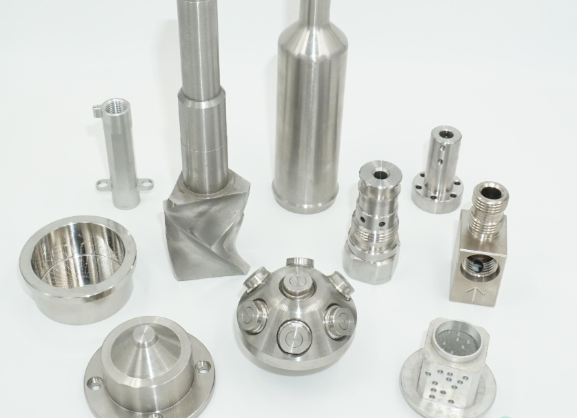
| Stainless Steels | 304, 316, 303, 410, 17-4PH | Corrosion-resistant fittings, food equipment, medical parts |
| Aluminum Alloys | 6061, 6082, 7075, 2024 | Lightweight components, aerospace, electronics housings |
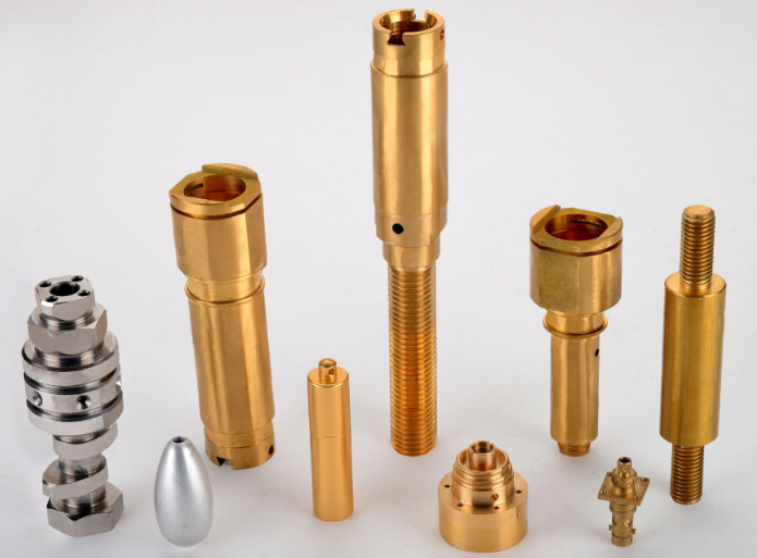
| Copper and Copper Alloys | Brass (e.g., C36000), bronze, pure copper | Electrical components, valves, decorative hardware |
| Titanium Alloys | Ti-6Al-4V and variants | Medical implants, aerospace parts requiring high strength and low weight |
| Nickel-Based Alloys | Inconel, Hastelloy, Monel | High-temperature and corrosion-resistant components |
| Engineering Plastics | Delrin (POM), Nylon, PTFE, PEEK, UHMWPE | Insulators, bearings, seals, medical and food-contact parts |
Each material has recommended cutting speeds, feeds, and tool grades. For example, free-cutting brasses permit high speeds and produce short chips, while stainless steels may require lower speeds and tougher cutting tools.
Typical Tolerances and Surface Finish in CNC Turning
CNC turning can achieve tight dimensional tolerances and high-quality surfaces, depending on the machine, tools, setup, and material.
Dimensional Tolerances
Common tolerance ranges for CNC turning are:
- General dimensions: ±0.05 mm (±0.002 in) are often achievable without special measures.
- Precision features: ±0.01 mm (±0.0004 in) or better may be possible with stable conditions and quality machines.
- Fits and mating surfaces: tolerances based on standards (e.g., ISO fits) are frequently used.
To maintain tight tolerances:
- Thermal stability (coolant temperature, ambient temperature) is important.
- Consistent tool condition and tool offset management are necessary.
- Proper clamping and minimized overhang reduce part deflection.
Surface Finish
Surface roughness is often specified in Ra (arithmetical mean roughness). Typical values from CNC turning are:
- Roughing passes: Ra 3.2–6.3 μm.
- Finishing passes: Ra 0.8–1.6 μm.
- Fine finishing or with specialized tooling: Ra 0.4 μm or lower in some cases.
The following factors influence surface finish:
- Feed rate: lower feed generally improves finish.
- Nose radius: larger radius may produce smoother surfaces.
- Tool wear: worn tools degrade finish.
- Machine condition: backlash, vibration, and spindle runout affect surface quality.
Tooling for CNC Turning
Cutting tools are a critical part of the turning process. Modern CNC turning uses indexable inserts and modular tool holders, enabling quick changes and consistent performance.
Insert Materials
Common insert materials include:
- Carbide: widely used due to good hardness and toughness. Suitable for a broad range of materials and cutting conditions.
- Cermet: offers excellent wear resistance and good surface finishes, typically used for finishing steels.
- Ceramic: used for high-speed cutting of hard materials and heat-resistant alloys.
- Cubic boron nitride (CBN): used for hardened steels and high-hardness materials.
- Polycrystalline diamond (PCD): used for non-ferrous metals and plastics where extremely good finish and long tool life are required.
Tool Holder Systems
Tool holders secure the insert and provide stability. Features include:
- Shank size and shape, which must match the turret or tool post specifications.
- Clamping method (top clamp, wedge clamp, or lever lock) to secure inserts.
- Coolant-through capability for delivering fluid directly to the cutting edge.
Tool Selection Considerations
When selecting tools for a given job, consider:
- Material group and hardness.
- Required operations (roughing vs. finishing, grooving, threading, etc.).
- Part geometry and accessibility (internal vs. external features, small bores).
- Desired tool life and changeover frequency.
Workholding in CNC Turning
Proper workholding ensures the part is secure and aligned with the spindle axis, which is essential for precision and safety.
Chucks
Standard 3-jaw self-centering chucks are common for round bar and most cylindrical parts. 4-jaw independent chucks allow non-round or off-center clamping. Key parameters:
- Maximum clamping diameter and minimum gripping length.
- Jaw type (soft jaws for custom profiles, hard jaws for general work).
- Clamping force and repeatability.
Collets
Collet chucks offer more precise and uniform gripping for bar stock or small parts. They are often used for high-precision or high-speed operations, especially with automatic bar feeders.
Tailstock and Centers
For long or slender parts, a tailstock with a live or dead center supports the free end of the workpiece. This reduces deflection and vibration, improving dimensional accuracy and surface finish.
Programming Basics for CNC Turning
CNC turning programs typically use G-code. While CAM software is widely used, understanding basic commands helps you read, debug, and modify programs.
Coordinate System
Most CNC lathes use:
- Z-axis along the spindle centerline (positive away from the chuck).
- X-axis radial direction (often programmed as diameter values rather than radius).
- Work coordinate systems like G54 to define the part zero.
Common G-Code Commands
Typical commands in a simple turning program include:
- G00: rapid positioning.
- G01: linear interpolation (cutting feed motion).
- G02/G03: circular interpolation (rare in basic turning, more in contouring).
- G96/G97: constant surface speed mode and constant rpm mode.
- G71/G72: roughing and facing cycles on some controls.
- G76 or similar: threading cycles.
Tool Offsets and Compensation
Tool offsets (e.g., geometry and wear offsets) are used to adjust tool position without editing program coordinates. Cutter nose radius compensation can be used for accurate profiling with non-sharp tool tips.
Finishing, Heat Treatment, and Secondary Processes
Turned parts sometimes require additional processing steps depending on functional and aesthetic requirements.
Post-Machining Operations
Common steps after turning include:
- Heat treatment to increase hardness, strength, or wear resistance.
- Grinding of critical surfaces for very tight tolerances or fine finishes.
- Surface treatments such as anodizing (aluminum), plating, or coating for corrosion resistance or appearance.
Cleaning and Packaging
Parts usually undergo cleaning to remove cutting fluids and chips. Controlled packaging may be needed to prevent damage to precision surfaces and to keep sets or assemblies organized.
Advantages and Limitations of CNC Turning
Understanding the strengths and limitations of CNC turning helps you choose the right process for your parts.
Advantages
- High dimensional accuracy and repeatability for cylindrical parts.
- Efficient production of rotationally symmetric components, even in large quantities.
- Consistent quality when processes are well controlled.
- Ability to machine a wide variety of materials with appropriate tooling.
- Reduced manual intervention compared to conventional (manual) lathes.
Limitations and Considerations
- Less suitable for parts dominated by prismatic or non-rotational features; milling or other processes may be more efficient.
- Workholding of very irregular shapes can be complex and may require special fixtures.
- Very deep, small-diameter internal features can be limited by tool rigidity.
Common Pain Points When Starting with CNC Turning
Beginners often encounter specific issues when they first work with CNC turning. Being aware of them supports better planning and reduces trial-and-error.
Programming and Setup Errors
Incorrect zero points, tool offsets, or coordinate values can cause crashes or scrap parts. Careful verification of programs and step-by-step dry runs help prevent these problems.
Tool Wear and Unexpected Breakage
Insufficient monitoring of tool wear can lead to sudden tool failures, poor surface finish, or dimensional drift. Establishing a tool life schedule and performing regular visual checks are effective preventive measures.
Workpiece Deflection
Long, slender parts may bend under cutting forces, leading to tapered dimensions or chatter marks. Using tailstock support, reducing overhang, and optimizing cutting parameters can mitigate these issues.
How to Choose a CNC Turning Service or Supplier
If you do not operate your own machines, selecting the right CNC turning supplier is important for quality and reliability.
Capabilities and Equipment
Verify that the supplier’s machines can handle your part dimensions, material, and volume. Consider:
- Maximum turning diameter and length.
- Availability of live tooling if you need drilled or milled features in one setup.
- Experience with your material (e.g., stainless steel, titanium, plastics).
Quality Systems and Inspection
Check if the supplier has established quality procedures, including:
- Incoming material control and traceability.
- In-process inspection and statistical checks.
- Final inspection reports, especially for critical or regulated parts.
Engineering Support
Suppliers with strong engineering support can assist with design-for-manufacturing (DFM), suggesting adjustments to dimensions, tolerances, or features that reduce cost and lead time while maintaining function.
CNC Turning with XCM: Precision Parts, Fast Turnaround
At XCM, CNC turning is one of our core strengths. With our own factory, advanced multi-axis turning centers, and a skilled engineering team, we produce high-precision shafts, bushings, pins, and complex turned parts for customers worldwide. From small prototype batches to mass production, we focus on tight tolerances, stable quality, and cost-effective machining. Simply send us your 3D CAD files or drawings, and XCM will support you with professional DFM advice, competitive pricing, and fast lead times—helping you bring better parts to market, faster.
FAQ About CNC Turning
What is CNC turning?
CNC turning is a computer-controlled machining process where a rotating workpiece is shaped using cutting tools to create cylindrical, conical, or threaded parts.
How is CNC turning different from CNC milling?
In CNC turning, the workpiece rotates and the tool moves, while in CNC milling, the cutting tool rotates and the workpiece is usually stationary. Turning is best for cylindrical parts.
What are the benefits of CNC turning?
High precision and repeatability
Efficient for round or cylindrical parts
Faster production compared to manual turning
Ability to create threads, grooves, and tapers in one setup
How do I decide between CNC turning and CNC milling?
If your part is primarily cylindrical and features are arranged around a central axis, CNC turning is usually the most efficient process. If your part has many flat faces, pockets, and features that are not symmetric about a single axis, CNC milling is more appropriate. For some parts, a combination is ideal: turning for the main cylindrical body and milling for secondary features, either on a turning center with live tooling or on a separate machining center.
What types of parts are best suited for CNC turning?
CNC turning is best suited for rotationally symmetric parts such as shafts, pins, bushings, sleeves, couplings, and threaded connectors. Parts with multiple diameters, shoulders, grooves, and internal bores are commonly produced on lathes. While turning centers with live tooling can add some milled features, parts dominated by flat surfaces and complex pockets are generally more efficient to produce with CNC milling.
