
CNC milling is one of the most widely used machining processes in modern manufacturing. It enables precise, repeatable creation of complex parts from metals, plastics, and other materials by removing material with a rotating cutting tool controlled by a computer.
Definition of CNC Milling
CNC milling (Computer Numerical Control milling) is a subtractive manufacturing process in which a rotating, multi-point cutting tool removes material from a stationary or moving workpiece. The motion of the tool and workpiece is governed by computer-generated numerical commands, typically written in G-code.
The process is executed on CNC milling machines that combine a mechanical milling center with a CNC controller, servo drives, feedback systems, and a set of cutting tools. These machines can produce prismatic and sculpted surfaces, slots, pockets, holes, threads, and three-dimensional contours with high accuracy and repeatability.
Core Principles of CNC Milling
CNC milling is based on several fundamental technical principles that collectively determine process capability, accuracy, and efficiency.
Coordinate Systems and Machine Axes
CNC milling uses Cartesian coordinate systems to define tool position and part geometry. The machine coordinate system is established by the machine builder, while the work coordinate system is defined by the operator when setting up the job.
Typical linear axes are:
- X-axis: left–right movement
- Y-axis: front–back movement
- Z-axis: up–down movement
Rotary axes, when present, are often designated as A, B, and C. For example, the A-axis rotates around X, B around Y, and C around Z. The combination of linear and rotary axes defines the machine’s ability to approach the part from different directions and machine complex geometries in fewer setups.
Tool–Workpiece Relative Motion
Milling is characterized by the relative motion between the rotating cutting tool and the clamped workpiece. Material removal occurs when the cutting edges of the tool penetrate the workpiece surface at a specified depth and advance along a programmed path.
Two fundamental motion aspects are:
- Primary motion: tool rotation (spindle speed)
- Secondary motion: feed motion of the tool or workpiece along one or more axes
Most modern CNC mills are “end-milling dominant,” meaning most operations are accomplished using end mills that remove material with the periphery and/or end cutting edges.
Cutting Parameters and Their Roles
The behavior of the milling process is largely determined by key process parameters:
Spindle speed (n)
Rotational speed of the tool, usually expressed in revolutions per minute (rpm). Spindle speed is selected based on cutting speed recommendations for the specific workpiece material and tool material.
Approximate cutting speed ranges (typical values, actual recommendations depend on tool geometry, coating, machine rigidity, and coolant):
| Workpiece material | Common tool material | Typical cutting speed range (m/min) |
|---|---|---|
| Low carbon steel (e.g., AISI 1018) | Carbide | 120–220 |
| Alloy steel (quenched and tempered) | Carbide | 70–150 |
| Stainless steel (austenitic) | Carbide | 60–140 |
| Aluminum alloys (e.g., 6061, 7075) | Carbide | 250–600 |
| Copper alloys | Carbide | 150–350 |
| Titanium alloys (e.g., Ti-6Al-4V) | Carbide | 40–80 |
| Nickel superalloys | Carbide | 20–60 |
| Engineering plastics (e.g., POM, PEEK) | Carbide / HSS | 150–400 |
Spindle speed (rpm) is usually computed from the cutting speed (Vc) and tool diameter (D):
n (rpm) = (1000 × Vc) / (π × D), where Vc is in m/min and D in mm.
Feed rate (vf)
Linear speed at which the tool advances relative to the workpiece, expressed in mm/min or mm/rev. It is often derived from feed per tooth (fz), number of teeth (z), and spindle speed (n):
vf (mm/min) = fz × z × n
Feed rate affects chip thickness, surface quality, tool life, and cutting forces. Excessive feed can cause tool breakage and poor finish; too low a feed may cause rubbing rather than cutting and increase heat generation.
Depth of cut (ap) and width of cut (ae)
Depth of cut is the penetration of the tool into the workpiece, measured in the direction perpendicular to the machined surface. Width of cut is the engagement of the tool in the radial direction. These parameters primarily influence material removal rate and cutting forces.
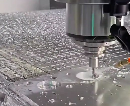
Material Removal Mechanism
In milling, each cutting edge periodically engages and disengages the workpiece as the tool rotates. This intermittent cutting produces discrete chips. The mechanics include:
1. Elastic and plastic deformation of the workpiece material ahead of the cutting edge.
2. Shear along a primary shear plane forming a chip that flows along the rake face of the tool.
3. Friction between chip and rake face and between flank face and newly machined surface.
The resulting process generates heat in the cutting zone. Proper selection of tool material, coatings, cutting parameters, and coolant application is required to control temperature, maintain tool life, and ensure dimensional stability.
Key Components of a CNC Milling System
A CNC milling system consists of mechanical, electrical, and software components that together execute machining operations with precision.
Machine Structure
The machine structure provides stiffness, accuracy, and vibration damping. Major elements include:
- Base and column: main support structures, often cast iron for high stiffness and damping
- Table: supports the workpiece or fixtures and moves along one or more axes
- Spindle head: houses the spindle and motor, moves along the vertical or other axes
- Guideways: linear guides or box ways providing accurate, low-friction motion
High rigidity and precise alignment are essential to minimize deflection, maintain tolerances, and produce consistent surface quality.
Spindle and Drive System
The spindle rotates the cutting tool and is driven by an electric motor. Key characteristics include:
1. Maximum spindle speed (e.g., 6,000–30,000 rpm depending on machine type)
2. Power rating (kW or hp), determining the allowable material removal rate
3. Torque characteristics, particularly important for heavy roughing at lower speeds
4. Spindle taper (e.g., ISO, CAT, BT, HSK) defining tool holder compatibility
Modern spindles may be equipped with built-in motors (motor spindles) for high-speed milling or belt/gear-driven configurations for heavy-duty cutting.
Feed Drives and Motion Control
Servo motors, ball screws, linear motors, and feedback systems (encoders, linear scales) work together to provide accurate positioning and interpolation along multiple axes. The CNC controller calculates and synchronizes motion commands to achieve the programmed toolpath with specified feed rate and acceleration/deceleration profiles.
Tooling System
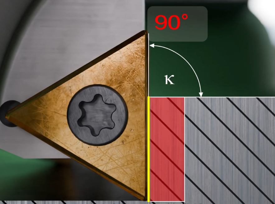
The milling tooling system comprises tool holders, cutting tools, and an automatic tool changer (ATC) when present. Important aspects include:
1. Tool holder: connects the cutting tool to the spindle (e.g., collet chuck, end mill holder, hydraulic chuck). Holder selection affects runout, balance, and gripping force.
2. Cutting tools: end mills, face mills, drills, reamers, and other tools made of carbide, high-speed steel, cermet, ceramics, or PCBN/PCD, depending on materials and operations.
3. ATC and magazine: allow automatic tool changes during a machining cycle, reducing manual intervention and setup time.
CNC Controller and Programming Interface
The CNC controller interprets part programs and converts them into coordinated motion and auxiliary commands. Core functions include:
1. Processing of G-code and M-code instructions
2. Interpolation (linear, circular, and, when applicable, spline interpolation)
3. Tool length and radius compensation
4. Coordinate system and zero offset management
5. Feed rate and spindle speed control, overrides, and look-ahead
The operator interacts with the controller through a human–machine interface (HMI), using a keyboard, touch screen, and hard keys to load programs, set offsets, and monitor the process.
Workholding and Fixturing
Workholding devices ensure the workpiece is rigidly clamped and accurately positioned. Common solutions include:
1. Machine vises and clamps for prismatic parts
2. Modular fixturing systems with T-slot or grid plates
3. Dedicated fixtures for high-volume production or complex parts
4. Rotary tables and trunnions for multi-axis positioning
Poor workholding can lead to vibration, dimensional errors, and poor surface finish.
Types of CNC Milling Machines
CNC milling machines are classified based on spindle orientation, number of controlled axes, and construction. The choice of machine type affects machinable geometries, productivity, and cost.
Vertical CNC Milling Machines
Vertical machining centers (VMCs) have a vertically oriented spindle. Common configurations include:
1. C-frame VMC: spindle moves vertically (Z), table moves in X and Y directions
2. Gantry-type vertical mill: gantry moves over a fixed table, suitable for large parts
VMCs are widely used due to versatility, lower cost compared with horizontal machines, and ease of setup for many parts. They are well-suited for plates, molds, and general prismatic components.
Horizontal CNC Milling Machines
Horizontal machining centers (HMCs) have a horizontally oriented spindle, often with an integrated rotary table (B-axis) and pallet changer. Advantages include:
1. Natural chip evacuation due to gravity
2. Better access to multiple sides of the workpiece with a rotary table
3. High productivity in multi-face machining and high-volume production
HMCs are common in automotive, aerospace, and general machinery industries for parts requiring multi-side machining and high throughput.
Universal and Multi-Axis Milling Centers
Universal milling centers combine vertical and horizontal capabilities, or provide tilting spindles and rotary tables. Multi-axis machines (4-axis and 5-axis) provide additional rotational axes for complex geometries.
| Machine type | Typical axes | Main capabilities |
|---|---|---|
| 3-axis VMC | X, Y, Z | Flat surfaces, slots, pockets, simple 3D contours |
| 3+1 or 3+2 axis mill | X, Y, Z + one or two indexable rotary axes | Multi-side indexing, improved access without continuous 5-axis motion |
| 4-axis continuous mill | X, Y, Z + one continuous rotary axis (A or B) | Helical surfaces, cylindrical features, partial 3D sculpting |
| 5-axis simultaneous mill | X, Y, Z + two continuous rotary axes | Complex freeform surfaces, undercuts, high-precision aerospace and medical parts |
Specialized CNC Milling Machines
Beyond standard machining centers, specialized configurations include:
1. CNC milling–turning centers: combine milling with turning operations in one setup
2. High-speed machining centers: high-rpm spindles for light, fast cuts in molds and aluminum structures
3. Portal and gantry mills: for large and heavy components such as dies, molds, and structural frames
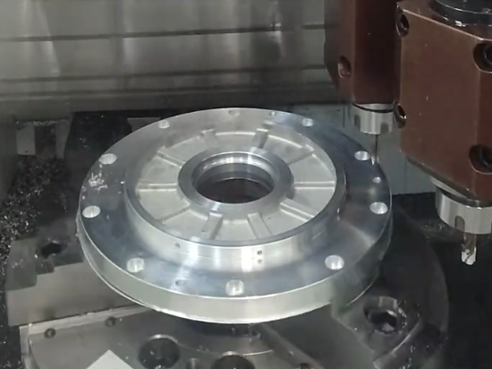
Common CNC Milling Operations
CNC milling executes a range of cutting operations, often combined in a single program to transform raw stock into a finished part.
Face Milling
Face milling creates flat surfaces by cutting with the face of a rotating tool, typically a face mill. It is often used as the first operation to level the top surface and establish a reference plane. Large-diameter tools and high feed rates are common for efficient stock removal.
Peripheral (Side) Milling
Peripheral milling removes material using the outer circumference of the tool. It is used for machining profiles, straight edges, and side surfaces. Climb milling (tool rotation and feed in same direction) is often preferred for better surface finish and tool life, provided machine backlash is well controlled.
Slotting and Pocketing
Slotting creates grooves or keyways, while pocketing removes material from internal areas. These operations often use end mills with specific geometries (e.g., center-cutting tools for plunging). Toolpath strategies may include zig-zag, circular, or trochoidal paths to manage cutting forces and chip evacuation.
Drilling, Boring, and Reaming on CNC Mills
CNC milling machines frequently perform hole-making operations:
1. Drilling: produces initial holes using twist drills or special drill types
2. Boring: enlarges existing holes with improved accuracy and roundness
3. Reaming: finishes holes to tight tolerance and smooth surface
Combining these operations in a single setup improves positional accuracy and reduces manufacturing time.
Thread Milling
Thread milling uses a rotating tool with thread profile to cut internal or external threads. Benefits include:
1. Ability to produce threads with different diameters using the same tool (within limits)
2. Reduced cutting forces and risk of breakage in difficult materials
3. High-quality threads with better control of size and form
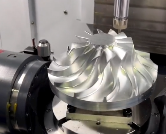
3D Contouring and Freeform Surface Milling
3D milling uses ball nose, tapered ball, and other special end mills to generate complex shapes in molds, dies, turbine blades, orthopedic implants, and other parts. Toolpaths are generated from 3D CAD models using CAM software and may include roughing, semi-finishing, and finishing passes with progressively finer stepovers and stepdowns.
Materials Used in CNC Milling
CNC milling supports a wide range of engineering materials. Material selection influences cutting parameters, tool choice, achievable tolerances, and surface finish.
Metals
Common metallic materials include:
1. Aluminum alloys: widely used for their machinability, low density, and good mechanical properties. Typical applications are aerospace structures, housings, fixtures, and prototypes.
2. Steel and stainless steel: applied in structural parts, shafts, brackets, tooling components, and many industrial products. Machinability varies with composition and heat treatment.
3. Copper and brass: used for electrical components, heat exchangers, and decorative parts. They typically exhibit good machinability but may require attention to built-up edge and chip control.
4. Titanium and nickel alloys: preferred in aerospace, medical, and high-temperature applications due to high strength and corrosion resistance. They require appropriate tooling and conservative cutting parameters.
Plastics and Composites
CNC milling is also common for non-metallic materials:
1. Engineering plastics (e.g., POM, PEEK, PC, PA): used for precision components requiring low weight, low friction, or chemical resistance.
2. Fiber-reinforced composites: carbon fiber or glass fiber composites require specific tools and strategies to avoid delamination, fiber pull-out, and excessive tool wear.
For plastics, controlling heat and avoiding melting or deformation are essential. Use of sharp tools, appropriate speeds and feeds, and sometimes air blast for chip removal is typical.
CNC Milling Workflow and Process Steps
The CNC milling workflow transitions from digital design to finished physical parts through a series of well-defined steps.
1) Design and CAD Modeling
The process starts with a digital 2D drawing or 3D CAD model defining the part geometry, dimensions, tolerances, and surface finish requirements. Proper design for milling considers tool access, minimum radii, wall thickness, and fixturing requirements.
2) Process Planning and CAM Programming
In computer-aided manufacturing (CAM), the programmer selects machining strategies, tools, feeds and speeds, and cutting sequences. CAM software then generates toolpaths and outputs G-code tailored to the specific CNC controller.
Planning also involves selecting reference faces, work coordinate systems, and the sequence of operations (roughing, semi-finishing, finishing, and drilling). Toolpath optimization can significantly affect cycle time and tool life.
3) Machine Setup and Workpiece Preparation
Setup operations include:
1. Installing appropriate tools and verifying lengths and diameters
2. Mounting the workpiece using vises, fixtures, or clamps
3. Setting workpiece zero (work coordinate system) by touching off tools or using probes
4. Checking clearance, toolpath simulations, and dry-runs as needed
Accurate and stable setup is essential to achieving specified tolerances and surface quality.
4) Execution of Machining Operations
Once setup is complete, the program is executed. The machine performs automated operations as programmed, including:
1. Automatic tool changes and spindle speed adjustments
2. Feed rate changes for roughing and finishing
3. Coolant on/off commands and air blast control
The operator monitors the process for unusual noises, vibration, chip formation, tool wear, and potential collisions, adjusting parameters if allowed and necessary.
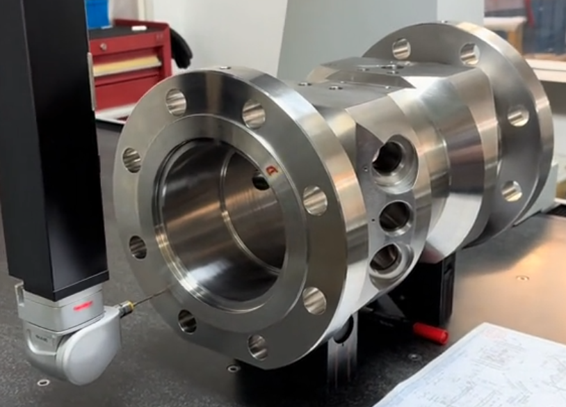
5) Inspection and Quality Verification
Post-machining inspection verifies conformance to specifications. Common verification steps include:
1. Dimensional measurement with calipers, micrometers, bore gauges, and height gauges
2. Coordinate measuring machine (CMM) inspection for complex geometries
3. Surface roughness measurement using profilometers when specified
4. Visual inspection of edges, burrs, and overall surface quality
Feedback from inspection may lead to program adjustments, tool changes, or process parameter refinement.
Typical Features Produced by CNC Milling
CNC milling can generate a broad range of geometric features on parts.
Flat Surfaces and Planes
Face milling and end milling create reference planes, sealing surfaces, and mounting faces. High flatness and parallelism can be achieved with proper tool selection and process control.
Slots, Pockets, and Cavities
Slots may be straight, T-shaped, or dovetail, while pockets can be open or closed. Cavities are common in mold and die applications, requiring careful roughing and subsequent finishing to meet dimensional and surface requirements.
Holes, Counterbores, and Countersinks
CNC mills can produce holes with precise location and depth. Additional features such as counterbores and countersinks facilitate assembly with fasteners and fittings. Using the same setup for multiple hole types ensures consistent positional accuracy.
Contours, Chamfers, and Fillets
Profiles along 2D and 3D paths, chamfers for edge deburring and assembly, and fillets for stress reduction and improved flow are common. Tool radius and strategy selection influence the accuracy and smoothness of these features.
Threads and Gear-Related Features
CNC milling can create threads through thread milling and generate gear-like features or spline profiles when combined with rotary axes. Dedicated CAM modules help define the correct toolpaths for such specialized geometries.
Accuracy, Tolerances, and Surface Finish in CNC Milling
CNC milling is valued for its ability to produce tight tolerances and controlled surface finishes, but achievable levels depend on machine condition, setup, tools, and process control.
Dimensional Accuracy and Tolerance Ranges
Typical achievable tolerances on well-maintained CNC milling machines are:
1. General tolerances: ±0.05 mm to ±0.1 mm for standard production
2. Precision features: ±0.01 mm to ±0.02 mm with appropriate machine, tooling, and process
3. High-precision applications: ±0.005 mm or better on specialized equipment and controlled environments
Factors affecting accuracy include thermal expansion, machine wear, fixture rigidity, tool deflection, and calibration of CNC axes.
Geometric Tolerances
CNC milling can produce features with controlled flatness, perpendicularity, parallelism, position, and runout. Geometric dimensioning and tolerancing (GD&T) provides a framework for specifying these requirements and must be taken into account during process planning and fixturing design.
Surface Roughness and Finish
Surface finish is often specified in terms of Ra (arithmetical mean roughness). Approximate ranges for milling are:
1. Roughing passes: Ra = 3.2–12.5 µm or higher
2. Semi-finishing: Ra = 1.6–3.2 µm
3. Finishing passes: Ra = 0.4–1.6 µm, sometimes lower with optimized conditions
Factors influencing surface finish include tool geometry, feed per tooth, step-over, cutting speed, machine vibration, and coolant application. With fine stepovers, sharp tools, and stable conditions, CNC milling can often eliminate the need for secondary grinding in some applications.
Key Parameters and Data for CNC Milling Processes
Effective CNC milling requires quantitative understanding of several parameters beyond speeds and feeds.
Material Removal Rate (MRR)
Material removal rate indicates productivity and is typically expressed in cm³/min or in³/min. For milling:
MRR = ap × ae × vf
where ap is axial depth of cut, ae is radial width of cut, and vf is feed rate. Higher MRR increases productivity but may raise cutting forces, vibration, and heat, affecting tolerances and tool life.
Tool Life and Wear Mechanisms
Tool life is affected by abrasion, adhesion, diffusion, oxidation, and mechanical breakage. Major wear types include flank wear, crater wear, chipping, and notch wear at depth-of-cut boundaries. Monitoring wear and replacing tools at appropriate intervals helps maintain dimensional consistency and surface quality.
Coolant and Lubrication
Coolants and lubricants serve to evacuate chips, reduce cutting temperature, and lower friction. Typical options are:
1. Flood coolant: emulsion or oil-based, applied in large volume
2. Minimum quantity lubrication (MQL): small amounts of oil dispersed in air stream
3. Dry machining with air blast: primarily for chip removal, used in specific applications and materials
Selection depends on material, tool, environmental requirements, and part cleanliness specifications.
Applications of CNC Milling
CNC milling is used in many industries due to its flexibility, precision, and ability to handle low, medium, and high production volumes.
Automotive and Transportation
Applications include engine components, transmission housings, suspension parts, brackets, tooling, and fixtures. CNC milling supports both high-volume components and prototype or low-volume parts for specialty vehicles.
Aerospace and Defense
High-performance requirements drive the use of CNC milling for structural airframe elements, turbine components, housings, brackets, and tooling. Multi-axis milling is often essential for complex aerospace geometries and difficult-to-machine alloys.
Medical Devices and Implants
CNC milling produces orthopedic implants, surgical instruments, and medical device housings with strict dimensional and surface requirements. Biocompatible materials such as titanium, stainless steel, and cobalt-chromium alloys are common.
Mold, Die, and Tooling Manufacture
Injection molds, die-casting molds, forging dies, and stamping tools rely heavily on CNC milling for cavity creation and fine surface finishing. 3D contouring with ball nose cutters and multi-axis strategies is integral to these applications.
General Engineering and Prototyping
CNC milling is widely used for jigs, fixtures, machine components, and functional prototypes. Its ability to rapidly produce accurate parts from a variety of materials makes it suitable for product development, custom equipment, and low-volume production.
Design Considerations for CNC-Milled Parts
Designing parts specifically for CNC milling promotes manufacturability, reduces cost, and improves quality.
Tool Access and Feature Orientation
Ensuring direct line-of-sight access for the cutting tool simplifies machining. For 3-axis machines, avoid hidden or undercut features that cannot be reached from a limited set of orientations. For multi-axis machines, access is more flexible but still constrained by tool length and collision risk.
Minimum Radii and Internal Corners
Since tools are cylindrical, internal corners always have a minimum radius. Designing corners with generous radii compatible with standard end mill sizes improves tool life and reduces cycle time. Very small radii can require small tools, leading to lower allowable feed rates and longer machining times.
Wall Thickness and Feature Proportions
Thin walls and slender features are prone to deflection and vibration, affecting dimensional accuracy and surface quality. Maintaining adequate wall thickness and reducing depth-to-width ratios for pockets and slots helps ensure stability and repeatability.
Tolerances and Surface Requirements
Specifying only necessary tight tolerances and fine surface finishes avoids unnecessary cost. Where possible, use standard tolerance classes and clearly define which surfaces require precision. Excessive or unspecified tight tolerances may increase setup complexity, inspection requirements, and cycle time.
Hole Sizes, Threads, and Standardization
Using standard drill and thread sizes allows utilization of common tooling and simplifies programming. Non-standard sizes may require boring, interpolation, or special tools, increasing machining time and complexity.
Practical Issues and Considerations in CNC Milling
Although CNC milling is highly capable, effective implementation requires attention to several practical aspects that can impact cost, quality, and throughput.
Fixturing Complexity and Setup Time
Complex parts with multiple faces or irregular geometries may demand custom fixtures or multiple setups. This can increase non-cutting time and introduce additional sources of error between setups. Thoughtful part design and process planning can reduce fixturing complexity.
Tool Selection and Inventory Management
A large variety of tool sizes, lengths, and geometries is often required to cover different materials and features. Managing this tool inventory, maintaining accurate tool data (lengths, diameters, wear offsets), and standardizing common tooling where possible helps improve consistency and reduce programming and setup effort.
Chip Control and Evacuation
Poor chip evacuation can cause recutting, surface damage, and tool breakage, particularly in deep pockets or when machining softer, stringy materials. Appropriate toolpath strategies, coolant direction, and chip-breaking geometries on tools are important to maintain reliable chip flow.
Thermal Effects and Dimensional Stability
Both the machine tool and the workpiece may undergo thermal expansion during long machining cycles or when cutting with high material removal rates. This can affect dimensions if not considered. Using appropriate cutting parameters, coolant, stable environmental conditions, and, when necessary, warm-up routines helps maintain dimensional consistency.
FAQ
What is CNC milling?
CNC milling is a computer-controlled machining process that uses rotating cutting tools to remove material from a workpiece and create precise parts.
What is the difference between CNC milling and manual milling?
CNC milling is automated and computer-controlled, while manual milling relies on operator skill and manual adjustments.
What are the advantages of CNC milling?
Advantages include tight tolerances, high efficiency, reduced human error, and suitability for both prototyping and production.
What is the difference between CNC milling and CNC turning?
In CNC milling, a rotating tool removes material from a generally stationary workpiece that may move linearly or rotate slightly on additional axes. In CNC turning, the workpiece rotates while a cutting tool moves primarily in linear axes to generate cylindrical shapes.
When should 5-axis CNC milling be considered?
5-axis CNC milling is particularly useful when parts have complex freeform surfaces, require machining of multiple faces in a single setup, or contain features that are difficult or impossible to reach on 3-axis machines.
