
A turbine rotor is the rotating core of a turbine that converts fluid energy (steam, gas, water, or wind) into mechanical rotational energy. It supports the blades or buckets, transmits torque to a generator or mechanical load, and must maintain structural integrity and dynamic stability under high stresses and temperatures.
This guide explains the fundamentals of turbine rotors, their key components, main functions, types across different turbine technologies, essential design parameters, materials, operating principles, and maintenance considerations.
Definition and Role of a Turbine Rotor
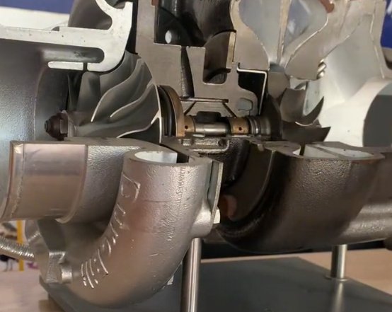
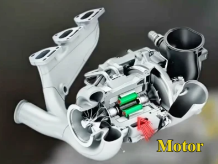
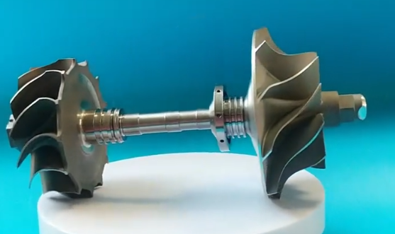
A turbine rotor is a mechanical assembly consisting of a shaft (or drum) and mounted blades, buckets, or discs that rotate as a working fluid flows through the turbine. It is mechanically coupled to a generator, compressor, pump, or driven machine to deliver useful power.
In any turbine, the rotor works together with the stationary components (stator, nozzles, diaphragms, guide vanes, casing) to form stages that progressively extract energy from the working fluid. The rotor is responsible for:
- Receiving momentum or pressure forces from the fluid via blades or buckets
- Transforming fluid energy into torque and rotational speed
- Transmitting power along its length to the driven equipment
- Maintaining precise alignment and clearances relative to stator components
Because the rotor is subject to high rotational speeds, centrifugal forces, thermal gradients, and cyclic loads, its design has a decisive impact on turbine performance, service life, and reliability.
Core Components of a Turbine Rotor
While the details differ between steam, gas, hydraulic, and wind turbines, most turbine rotors include a common set of core components.
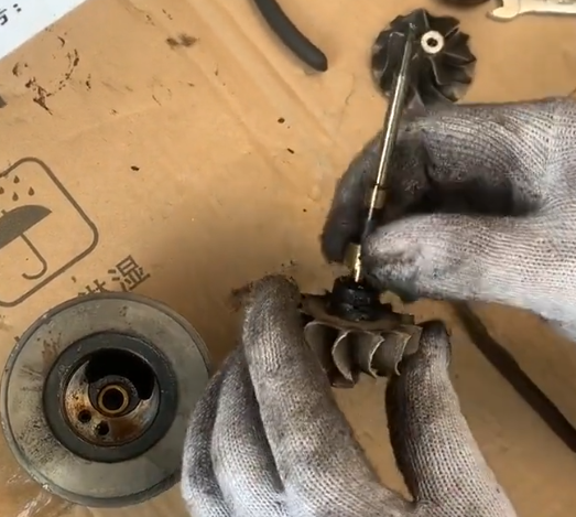
Shaft or Drum
The shaft (or drum in some steam turbines) is the central structural element of the rotor. It carries the blades/discs, transmits torque, and interfaces with bearings and couplings.
Key features:
- Geometries: solid shaft, built-up shaft with shrink-fitted discs, or integral drum
- Critical interfaces: journal surfaces, thrust collar, coupling flanges, blade roots seats, keyways (if used)
- Stress concentration control: fillets, undercuts, diameter transitions designed to reduce peak stresses
Blades, Buckets, or Runner Vanes
Blades or buckets are aerodynamically shaped components mounted on the rotor that interact directly with the working fluid. In hydraulic turbines, these may be called runner blades or vanes.
Primary functions:
- Convert fluid kinetic and/or pressure energy into tangential force on the rotor
- Control flow direction and velocity distribution
- Adjust performance (in some designs, via adjustable pitch or variable geometry)
At high rotational speeds, blades experience significant centrifugal and bending stresses, plus vibratory loads due to flow fluctuations and resonance phenomena. Blade-root attachment and tip-clearance control are critical design aspects.
Discs and Wheels
In many steam and gas turbines, blades are attached to discs or wheels that are mounted on the shaft. The disc transmits load from the blade ring into the shaft and contributes to rotor stiffness and mass distribution.
Design aspects include:
- Disc thickness profile to handle radial and hoop stresses
- Keyways, dovetail grooves, fir-tree slots, or other blade-root retention features
- Cooling passages (in gas turbines) for disc and blade root cooling
Bearings and Journals
Although bearings are not part of the rotor itself, the rotor has journal surfaces and, in some designs, thrust collars that interface with bearings. These interfaces are critical for rotor dynamics and alignment.
Common bearing-related rotor features:
- Journal diameter and surface finish tailored to hydrodynamic or rolling element bearings
- Thrust collar surfaces for axial load control
- Locating shoulders and chamfers for precise axial positioning
Couplings
Couplings connect the turbine rotor to a generator, gearbox, or other machinery. They must transmit torque reliably while accommodating misalignment within design limits.
Typical coupling interfaces on turbine rotors include:
- Flanged couplings with fitted bolts and precision-machined faces
- Flexible couplings for some industrial and aero-derivative gas turbines
- Keyed or spline connections in specific applications
Primary Functions of a Turbine Rotor
The turbine rotor fulfills several core functions that define its design requirements and operating conditions.
Energy Conversion
The rotor performs the mechanical energy conversion by capturing fluid energy through the blades and converting it to rotational kinetic energy. The fluid forces on the blades create a torque that accelerates or sustains the rotor’s rotation.
Energy conversion characteristics depend on:
- Blade profile and incidence angle
- Stage pressure ratio and velocity triangles
- Clearances, surface roughness, and leakage paths
Torque Transmission
The rotor transmits the generated torque from each stage to the output coupling. The shaft and discs must resist torsional shear stresses and avoid fatigue under cyclical load variations.
Torsional vibration analysis is used to ensure that natural frequencies of the rotor–train do not coincide with excitation frequencies within the normal operating speed range.
Support and Alignment
The rotor must maintain precise alignment relative to stator parts to keep clearances within specified limits. Excessive radial or axial displacement can cause rubbing, increased losses, or mechanical damage.
Key aspects include:
- Rotor straightness and controlled bow
- Correct positioning of journals and thrust surfaces
- Manufacturing tolerances for concentricity and runout
Dynamic Stability
At high speeds, the rotor behaves as a flexible body that can exhibit bending modes, whirl, and other dynamic phenomena. The rotor must be designed so that its critical speeds and mode shapes are compatible with the operating speed range and bearing configuration.
Dynamic stability considerations include:
- Mass and stiffness distribution along the rotor
- Damping from bearings and seals
- Balancing quality and residual unbalance control
Types of Turbine Rotors by Turbine Technology
Different turbine applications lead to different rotor configurations and design priorities. The following overview covers common rotor types in steam, gas, hydraulic, and wind turbines.
Steam Turbine Rotors
Steam turbine rotors are typically used in power generation and industrial process plants. They operate with high-pressure, high-temperature steam, often in multiple stages arranged from high-pressure (HP) to intermediate-pressure (IP) to low-pressure (LP) sections.
Common steam turbine rotor designs:
- Built-up rotors: separate discs shrunk onto a shaft, historically common in large machines
- Monobloc or integral rotors: forged in one piece with integral wheels or machined seats for blades
- Drum rotors: used in certain high-pressure sections, with long drums carrying rows of blades
Typical characteristics:
- Operating inlet steam pressure: often in the range of 8–25 MPa (depending on plant design)
- Inlet steam temperature: commonly 500–600 °C in modern units
- Rotational speed: 3000 rpm (50 Hz systems) or 3600 rpm (60 Hz systems) for large utility units; variable for industrial turbines
Steam turbine rotors must handle substantial thermal gradients during start-up, shut-down, and load changes, which influence rotor thermomechanical stress and life.
Gas Turbine Rotors
Gas turbine rotors are used in power plants, mechanical drive systems, and aero engines. They operate with high-temperature combustion gases and often include both compressor and turbine sections on the same shaft or multiple concentric shafts (spools).
Gas turbine rotor features:
- Disc-stack design in many heavy-duty gas turbines
- Single or multi-spool rotors (e.g., high-pressure and low-pressure rotors) in aero-derivative and aviation gas turbines
- Extensive cooling passages in turbine discs and blades for high-temperature operation
Typical ranges (values depend strongly on application and technology):
- Rotational speeds: from about 3000–3600 rpm in large heavy-duty units to tens of thousands of rpm in aviation engines
- Turbine inlet temperature: commonly above 1200 °C in modern designs, requiring advanced alloys and cooling strategies
Gas turbine rotors demand high-temperature strength, creep resistance, and fatigue resistance, as well as precise control of rotor dynamics due to high speed.
Hydraulic Turbine Rotors (Water Turbines)
In hydraulic turbines, the rotor is usually referred to as the runner. It operates in water flows and is used in hydroelectric power stations.
Common hydraulic rotor types:
- Francis runners: mixed-flow, typically vertical-shaft, used in medium head applications
- Pelton wheels: impulse turbines with buckets for high head, low flow applications
- Kaplan runners: axial-flow turbines with adjustable blades for low head, high flow conditions
Key design features:
- Resistance to cavitation damage
- High efficiency over a range of water heads and flows
- Robustness against debris and sediment in the water
Rotational speeds are determined by the turbine specific speed and head and can range from a few tens to several hundred rpm for large hydro units.
Wind Turbine Rotors
Wind turbine rotors convert wind kinetic energy into mechanical power on a low-speed shaft, typically driving a generator through a gearbox or directly in direct-drive designs.
Wind rotor features:
- Large-diameter rotors with 2 or 3 blades as the most common configuration
- Aerodynamic blade profiles optimized for varying wind speeds
- Pitch control systems for power regulation and load management
Typical parameters for utility-scale horizontal-axis wind turbines:
- Rotor diameters: often 80–180 m or more for modern onshore and offshore machines
- Rotational speeds: commonly in the range of 6–20 rpm at the rotor (before gearbox, if used)
Wind turbine rotors must sustain variable and turbulent wind loads, including gusts and directional changes, with long blade spans and relatively low rotational speeds.
Key Design Parameters and Engineering Considerations
Turbine rotor design involves balancing mechanical strength, dynamic behavior, aerodynamic or hydraulic performance, and manufacturability. Several core parameters govern rotor design.
Rotational Speed and Critical Speeds
The operating speed of the rotor is chosen based on the application (grid frequency, machine design) and interacts with the rotor’s natural frequencies (critical speeds). Designers aim to ensure that the normal operating range does not coincide with a critical speed or that passages through critical speeds during acceleration are acceptable.
Parameters considered:
- First and higher bending mode critical speeds
- Torsional natural frequencies
- Allowable overspeed margins (e.g., during trip events)
Stress and Strength Calculations
Rotor components are subject to combined stresses from rotation (centrifugal), torque, thermal gradients, pressure differentials, and occasional external loads. Stress analysis typically includes:
- Radial and hoop stresses in discs and shaft sections
- Bending stresses due to rotor weight, unbalance, and misalignment
- Thermal stresses arising from non-uniform temperature distributions
Design margins are set to prevent yielding, low-cycle fatigue, high-cycle fatigue, and, at high temperatures, creep damage over the intended service life.
Deflection, Runout, and Clearances
Allowable deflection and runout are controlled to maintain safe clearances between rotor and stator parts, especially in tight clearances regions such as blade tips, seals, and diaphragms.
Focused parameters include:
- Maximum permissible shaft runout at journals and couplings
- Acceptable rotor bow and thermal bow limits
- Deflection under load compared with minimum clearances
Mass Distribution and Balancing
Uniform mass distribution is vital to minimize unbalance forces that can lead to vibration. Both static and dynamic balancing steps are applied during rotor manufacturing and sometimes during maintenance.
Balancing practices typically include:
- Balancing in multiple planes along the rotor
- Adherence to balancing quality grades appropriate for turbine service
- Provision of balance correction features such as balance weights or material removal zones
Materials and Metallurgy of Turbine Rotors
Material selection for turbine rotors depends on operating temperature, stress levels, corrosion environment, and expected service life. The chosen materials must provide sufficient strength, toughness, fatigue resistance, and, for high-temperature turbines, creep resistance and oxidation resistance.
| Rotor Type | Common Material Categories | Key Properties Required |
|---|---|---|
| Steam turbine rotor (HP/IP) | Low-alloy and CrMoV steels, martensitic steels | High strength at elevated temperature, good toughness, resistance to thermal fatigue |
| Steam turbine rotor (LP) | Low-alloy steels, NiCrMo steels | Good toughness, resistance to stress corrosion and wet steam erosion |
| Gas turbine rotor discs | Nickel-base superalloys, CrMoV steels in cooler sections | High-temperature strength, creep resistance, oxidation resistance |
| Hydraulic turbine runner | Stainless steels (e.g., martensitic, duplex) | Cavitation resistance, corrosion resistance, adequate strength |
| Wind turbine rotor hub | Cast steels, nodular cast iron | Good toughness, fatigue resistance, castability for large components |
| Wind turbine blades (attached to rotor) | Fiber-reinforced composites (glass or carbon fiber) | High specific strength and stiffness, fatigue resistance, low weight |
Metallurgical quality is crucial for rotor reliability. Factors such as cleanliness (low inclusion content), controlled grain size, segregation control, and appropriate heat treatment are carefully managed.
Rotor Dynamics and Vibration Behavior
Rotor dynamics deals with the behavior of the rotating system under operational conditions. Turbine rotors must be stable against excessive vibration throughout the entire speed range from start-up to rated operation and shut-down.
Unbalance and Vibration
Unbalance arises from small deviations between the rotor’s geometric axis and its mass axis. Even minor unbalance at high speeds can produce significant radial forces. These forces can induce vibration, wear, and, in severe cases, mechanical damage.
To control unbalance:
- Precision machining and tight dimensional tolerances are applied
- Rotors are balanced in specialized balancing machines
- Periodic vibration monitoring is performed in operation
Critical Speeds and Mode Shapes
Critical speeds occur when the rotational speed matches one of the natural frequencies of the rotor–bearing system, causing resonance. At these speeds, vibration amplitude may increase sharply unless adequate damping is present.
Design and analysis steps include:
- Finite element modeling of the rotor, bearings, and supports
- Campbell diagrams to visualize frequency versus speed
- Specification of acceptable operating speed ranges relative to critical speeds
Interaction with Bearings and Seals
The rotor’s dynamic behavior is strongly influenced by bearing type (journal, tilting pad, rolling element) and by seals (labyrinth, brush, honeycomb, etc.). Fluid-film bearings and seals generate stiffness and damping forces that affect stability and response.
Proper design of bearing clearances, film thickness, lubrication conditions, and seal geometries is essential for stable rotor operation.
Working Principle: How a Turbine Rotor Operates
The fundamental working principle of a turbine rotor is based on the transfer of momentum and/or pressure from the working fluid to the rotor blades. While details differ between impulse and reaction turbines, the underlying mechanics involve conservation of energy and angular momentum.
Impulse Turbines
In impulse turbines, the fluid is expanded to a lower pressure in stationary nozzles before it enters the rotor. The high-velocity jets strike the rotor blades or buckets, changing direction and imparting momentum to the rotor.
Key characteristics:
- Most of the pressure drop occurs in the nozzles, not across the rotor
- Blade passages operate primarily with high kinetic energy flows
- Common in Pelton water turbines and some older steam turbine stages
Reaction Turbines
In reaction turbines, pressure drop occurs across both the stationary and rotating blade rows. Flow accelerates and expands through both stator and rotor passages, which act like nozzles.
Characteristics of reaction-based rotor operation:
- Combined action of pressure and velocity changes across the rotor blades
- Sensitive to radial and axial clearances
- Common in modern steam and gas turbines, as well as Francis and Kaplan turbines
In both impulse and reaction designs, the rotor must maintain the designed velocity triangles at the blade inlet and outlet to achieve high efficiency.
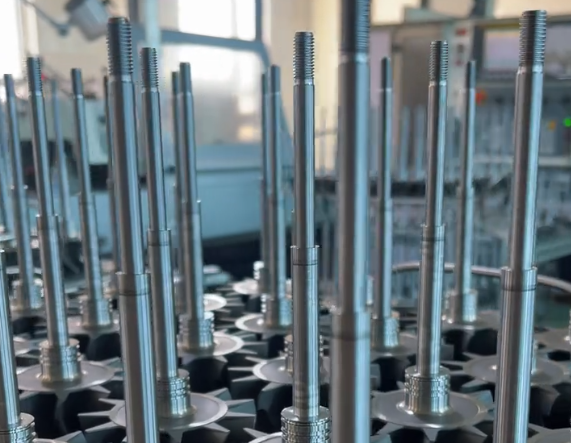
Manufacturing and Quality Control of Turbine Rotors
Rotor manufacturing is a specialized process that integrates forging or casting, extensive machining, heat treatment, and rigorous inspection. Quality control is aimed at ensuring material integrity, dimensional accuracy, and balance.
Forging and Casting
Large steam and gas turbine rotors are commonly made from forged steel or forged superalloys. For some wind turbine hubs and hydraulic turbine runners, casting is used due to complex geometries and size.
Critical steps include:
- Controlled solidification and forging ratios to minimize internal defects
- High-quality ingots or continuously cast billets
- Appropriate heat treatments (normalizing, quenching, tempering) to achieve desired microstructure
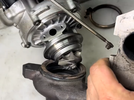
Machining and Blade Attachment
Precision machining is performed to create journals, coupling faces, disc profiles, and blade attachment features. Blade roots are fitted to rotor discs or rims using dovetail, fir-tree, or other specialized designs.
Machining considerations:
- Tight tolerances for concentricity and parallelism
- Surface finish requirements for critical interfaces (journals, coupling faces)
- Dimensional control of blade slots to ensure secure yet manageable assembly
Non-Destructive Testing and Inspection
To ensure integrity and detect potential defects, multiple non-destructive tests are used:
- Ultrasonic testing (UT) for internal discontinuities
- Magnetic particle testing (MT) for surface and near-surface cracks in ferromagnetic materials
- Dye penetrant testing (PT) for surface flaws
- Radiographic testing (RT) in specific cases for internal flaw detection
After assembly, rotational balancing and overspeed testing may be performed under controlled conditions to verify mechanical integrity and stability.
Operation, Monitoring, and Maintenance of Turbine Rotors
During service, turbine rotors are subject to wear, fatigue, corrosion, erosion, and possible damage from off-design events. Proper operation and maintenance practices extend rotor life and support safe, reliable turbine performance.
Common Rotor-Related Issues
Several practical issues can affect turbine rotor performance and integrity.
1. Vibration and Unbalance
Excessive vibration may indicate unbalance, misalignment, bearing problems, or damage. Persistent vibration can accelerate fatigue and wear of rotor and bearing components.
Symptoms and effects:
- Increased bearing temperatures and noise
- Elevated vibration amplitudes at one or more measurement locations
- Risk of rubbing between rotor and stationary parts
2. Thermal Stress and Rotor Bow
Uneven heating or cooling can produce thermal bow, where the rotor bends due to differential expansion. This can cause high vibration, clearance issues, and increased stress levels.
Typical causes include:
- Improper start-up or shut-down ramp rates
- Localized heating from steam admission patterns
- Uneven cooling during outages
3. Surface Damage, Corrosion, and Erosion
In steam and hydraulic turbines, wet steam or water droplets, as well as solid particles, can cause erosion on blade and rotor surfaces. Corrosion may occur due to water chemistry issues or contaminants.
Consequences include:
- Reduced blade efficiency
- Loss of material and change of blade profile
- Initiation points for fatigue cracks
Inspection and Maintenance Practices
Routine and periodic inspections are used to detect and address rotor issues before they lead to failures. Maintenance strategies depend on turbine type, operating regime, and plant requirements.
Common practices:
- Condition monitoring: continuous measurement of vibration, bearing temperature, and key process parameters
- Scheduled outages: detailed visual inspection of rotor surfaces, blades, and couplings
- Non-destructive examinations during outages: UT, MT, PT as applicable
- On-site or shop balancing: correction of unbalance identified through vibration analysis
In some cases, rotor life assessment studies are performed based on accumulated operating hours, cycles, stress histories, and inspection findings to decide on continued operation, refurbishment, or replacement.
Integration of the Rotor into the Turbine System
The rotor functions as part of a larger mechanical and thermodynamic system. Its performance and reliability depend on proper integration with stator components, bearings, seals, and control systems.
Key integration aspects:
- Axial thrust balance: managed via blade design, balance pistons, and thrust bearings
- Thermal expansion management: controlled via clearances, expansion joints, and support design
- Coupling alignment and shaft-line configuration: including gearbox or generator alignment in multi-rotor trains
Control systems, such as speed governors, pitch systems (in wind turbines), and steam or fuel control valves, indirectly influence rotor loading and dynamic behavior. Coordinated operation is necessary to avoid excessive mechanical stresses.
Typical Technical Parameters of Turbine Rotors
The following table summarizes representative parameter ranges for various turbine rotor types (actual values depend on specific designs and applications).
| Rotor Type | Typical Speed Range | Typical Diameter Range | Typical Operating Medium Conditions |
|---|---|---|---|
| Large steam turbine rotor (utility) | 3000–3600 rpm | Up to several meters at LP end | Inlet steam ~8–25 MPa, ~500–600 °C |
| Industrial steam turbine rotor | 1500–12000 rpm (depending on rating) | From several hundred mm to ~2 m | Wide range of steam pressures and temperatures |
| Heavy-duty gas turbine rotor | 3000–3600 rpm | Typically 1–2 m turbine section diameter | Turbine inlet temperature often >1200 °C |
| Aero engine gas turbine rotor | Tens of thousands of rpm | Disc diameters typically <1 m | High-pressure, high-temperature combustion gases |
| Francis hydro turbine runner | ~100–1000 rpm (depending on head and size) | Often 1–10 m diameter | Water flow with varying heads |
| Kaplan hydro turbine runner | ~50–300 rpm | Large diameters, often 3–10 m | Low head, high flow water |
| Utility-scale wind turbine rotor | ~6–20 rpm | ~80–180 m rotor diameter | Atmospheric wind, variable speed and direction |
Summary
A turbine rotor is the central rotating assembly in steam, gas, hydraulic, and wind turbines, responsible for converting fluid energy into mechanical power and transmitting that power to generators or other machinery. Its design integrates structural mechanics, aerodynamics or hydraulics, materials science, and rotor dynamics.
Key points include:
- The rotor consists of a shaft or drum, blades or buckets, discs or runner, and interfaces for bearings and couplings
- It must withstand high centrifugal, thermal, and cyclic loads while maintaining alignment and proper clearances
- Material selection and manufacturing quality are central to long-term reliability
- Rotor dynamics, including unbalance, critical speeds, and vibration behavior, are crucial design and operational considerations
- Effective monitoring, inspection, and maintenance are needed to manage wear, fatigue, and surface damage over the rotor’s service life
Understanding the basics, components, and functions of turbine rotors provides a foundation for analyzing turbine performance, diagnosing operational issues, and supporting reliable power generation and mechanical drive applications.
FAQ About Turbine Rotors
What is a turbine rotor?
A turbine rotor is the rotating part of a turbine that carries the blades and converts energy from fluid (steam, gas, or water) into mechanical rotational energy to drive a generator or mechanical system.
How are turbine rotors manufactured?
They are manufactured using forging, CNC machining, grinding, and sometimes welding for multi-piece designs, followed by heat treatment to achieve desired mechanical properties.
What are the key design considerations for turbine rotors?
Design focuses on rotor strength, blade attachment, aerodynamic efficiency, thermal expansion, vibration resistance, and fatigue life.
How is a turbine rotor balanced?
Dynamic balancing is performed using specialized balancing machines to ensure smooth rotation and reduce vibration during high-speed operation.
What industries use turbine rotors?
Turbine rotors are widely used in power generation (steam, gas, hydro), aviation (jet engines), marine propulsion, and industrial gas turbines.
