
A turbine blade is a precisely engineered aerodynamic component that extracts energy from a moving fluid (gas, steam, or liquid) and converts it into mechanical rotational power. Turbine blades are core elements in gas turbines, steam turbines, hydro turbines, and wind turbines, and they directly influence efficiency, power output, reliability, and service life of the entire unit.
This guide provides a comprehensive, engineering-focused overview of turbine blades, including their functions, types, main components, materials, design parameters, manufacturing and cooling methods, performance considerations, and major industrial applications.

Fundamental Function of a Turbine Blade
Turbine blades perform the energy conversion at the heart of a turbomachine. In simple terms, they convert the kinetic and/or pressure energy of a working fluid into shaft work on the turbine rotor. The specific function depends on the turbine type and the stage configuration, but the underlying principle is similar.
Key functional roles of a turbine blade include:
- Guiding and accelerating or decelerating the working fluid flow
- Converting fluid momentum change into torque on the rotor
- Enduring mechanical stresses due to rotation and gas/liquid forces
- Withstanding thermal loads, especially in high-temperature gas and steam turbines
- Maintaining aerodynamic performance over long service intervals
The flow direction and energy transfer mechanism differ slightly between impulse and reaction stages:
Impulse stages: Most of the pressure drop occurs across stationary nozzles; the moving blades primarily convert kinetic energy of the high-velocity jet into mechanical work.
Reaction stages: Pressure drop occurs in both stator (nozzle) and rotor (moving blades); the moving blades act like nozzles themselves and convert both pressure and kinetic energy into work.
Key Components in a Turbine Blade Assembly
Although geometries differ among gas, steam, hydro, and wind turbines, many turbine blades share a common set of structural elements. Understanding these components helps clarify design and performance discussions.
| Component | Description | Typical Functions |
|---|---|---|
| Airfoil (Blade Profile) | The curved, aerodynamic portion that interacts with the fluid | Generates lift or tangential force; defines stage efficiency and flow turning |
| Root | Portion that attaches the blade to the rotor disk or hub | Transfers centrifugal and gas loads; allows assembly, retention, and replacement |
| Platform (Shroud Platform) | Radial extension at the base of the airfoil forming the inner or outer gas path wall | Seals flow path, reduces leakage, provides structural stiffness |
| Tip | Outer end of the blade airfoil | Interfaces with casing or shroud; critical for minimizing tip leakage |
| Shroud (Interlocking Tip or Mid-Span) | Ring-like or interlocking feature at the blade tip or mid-span | Reduces vibration, leakage, and helps control dynamic behavior |
| Cooling Passages (High-Temp Blades) | Internal channels, holes, and cavities within the blade | Carry cooling air to keep metal temperature below allowable limits |
| Fir-tree or Dovetail Root Form | Specific interlocking geometry between blade root and disk slot | Ensures secure attachment, load transfer, and stress distribution |
In large gas and steam turbines, blades near the last stages can be very long, and additional features like mid-span snubbers or tie-wires may be used to control vibration and distribute stresses.
Classification of Turbine Blades by Turbine Type
Turbine blades can be classified in several ways, but one of the most practical approaches is by the type of turbine and working fluid. Each category imposes different aerodynamic, thermal, and mechanical requirements.
Gas Turbine Blades
Gas turbine blades operate with hot combustion gases, often at temperatures higher than the melting point of the base metal, and at very high rotational speeds. They are typically found in aircraft engines and industrial or power-generation gas turbines.
Main characteristics of gas turbine blades:
- High operating temperatures, often 900–1,300 °C at the blade inlet for modern engines
- High rotational speeds, commonly 3,000–15,000 rpm for large industrial units and much higher for aero engines
- Use of advanced nickel-based superalloys and sophisticated cooling schemes
- Complex 3D aerodynamics with twisted and lean profiles
Gas turbine blades are often divided into:
Compressor blades: Technically rotor blades in the compressor section, designed to increase air pressure (not turbine blades in the strict sense, but geometrically similar).
Turbine stator vanes (nozzles): Stationary blades that direct and accelerate hot gases onto turbine rotor blades.
Turbine rotor blades: Moving blades that extract energy from hot gases. These are usually the most thermally and mechanically loaded components.
Steam Turbine Blades
Steam turbine blades operate with high-pressure steam in power plants and industrial installations. While maximum steam temperatures are generally lower than gas turbine combustion gas temperatures, steam turbines have their own distinct operating conditions, including issues related to condensation and moisture in low-pressure stages.
Typical features of steam turbine blades:
- Operation with superheated and then gradually expanding steam
- Moderate to high temperatures (commonly 500–600 °C at high-pressure inlet)
- Wide range of blade lengths, from short high-pressure blades to very long low-pressure last-stage blades
- Attention to erosion and droplet-related damage in low-pressure wet-steam zones
Steam turbine blades are commonly divided into:
Impulse blades: Short, high-pressure stages where most pressure drop is in the stationary nozzles.
Reaction blades: Longer stages where pressure drop occurs in both fixed and moving rows, with smoother pressure gradients.
Hydro Turbine Blades (Hydraulic Turbines)
Hydro turbine blades, often called runners or runner blades, operate in water flow and are designed to extract energy from potential and kinetic energy of water. They are used in hydroelectric power plants.
Key aspects of hydro turbine blades:
- Operate in incompressible, relatively low-temperature water
- Large blade or runner sizes due to high mass flow and low flow velocities compared with gas/steam
- Focus on cavitation resistance, corrosion resistance, and hydraulic efficiency
Common hydro turbine runner types include:
Francis runner blades: Mixed-flow design, with water entering radially and exiting axially.
Kaplan runner blades: Axial-flow design with adjustable pitch blades; suited for low head, high flow sites.
Pelton buckets: In impulse-type Pelton turbines, the “blade” is a bucket-shaped element that intercepts high-velocity water jets.
Wind Turbine Blades
Wind turbine blades convert kinetic energy of wind into rotational energy of the rotor, which then drives a generator. They are large, lightweight, and designed for aerodynamic efficiency at relatively low tip speeds compared with aero engines.
Characteristics of wind turbine blades:
- Very large length (commonly 40–80 m for utility-scale turbines, with larger sizes used in some offshore installations)
- Use of composite materials (glass fiber, carbon fiber in polymer matrices)
- Low-density construction to minimize mass and bending loads
- Aerodynamic profiles optimized for a range of wind speeds and pitch angles
Impulse and Reaction Turbine Blade Designs
In both steam and gas turbines, blades may be part of impulse or reaction stages. The type is defined by how pressure and velocity changes are distributed between stationary and moving rows.
Impulse Blades
Impulse blades operate with the main pressure drop occurring in the stationary nozzles. The nozzles convert pressure energy into high-velocity jets. The moving blades then redirect the jet, changing its direction and reducing its velocity. The change in fluid momentum generates torque on the rotor.
Typical properties of impulse blades:
- Blade passages designed primarily for flow turning rather than strong pressure reduction
- Relatively constant static pressure across the moving row
- Distinctive bucket-like or curved profile
Reaction Blades
Reaction blades share the pressure drop with the stationary vanes. The moving blades themselves act as nozzles, with pressure decreasing and velocity increasing through the blade passages. The resulting lift-type forces generate work on the rotor.
Key features of reaction blades:
- Blade passages accelerate flow and reduce static pressure
- Pressure drop distributed between stator and rotor, often around 50:50 in classical designs
- Smoother pressure gradients and typically more continuous flow turning
The choice between impulse and reaction designs affects efficiency, stage loading, manufacturing complexity, and sensitivity to operating point deviations.
Materials Used for Turbine Blades
Material selection for turbine blades is driven by temperature, stress levels, corrosive or erosive environment, and economic requirements. Different turbine types use distinct material families.
Gas Turbine Blade Materials
Gas turbine blades, especially first-stage rotor blades and stator vanes, operate in the harshest conditions. They commonly use nickel-based or cobalt-based superalloys with high-temperature strength and creep resistance.
Typical material characteristics for hot gas turbine blades:
- High creep strength at temperatures above 900 °C
- Resistance to oxidation and hot corrosion
- Capability to be directionally solidified or single-crystal to reduce grain boundary weaknesses
- Compatibility with internal cooling passages and thermal barrier coatings
Examples of material forms include equiaxed superalloys, directionally solidified (DS) superalloys, and single-crystal (SX) superalloys. Coatings such as MCrAlY (where M is Ni, Co, or both) plus ceramic thermal barrier coatings are commonly applied to increase surface temperature capability.
Steam Turbine Blade Materials
Steam turbine blades typically operate at lower temperatures than gas turbines but must withstand moisture, erosion, and fatigue over long lifetimes. Martensitic and martensitic stainless steels are frequently used.
Typical requirements include:
- Good fatigue resistance under high-cycle vibratory loads
- Corrosion and erosion resistance in wet-steam regions
- High toughness, particularly for long last-stage blades
- Stable mechanical properties at 400–600 °C range
Long low-pressure blades may use advanced high-strength steels with optimized heat treatment to balance strength and toughness.
Hydro Turbine Blade Materials
Hydro turbine runner blades operate in water, often with dissolved oxygen and solids that can cause cavitation and erosion. Austenitic stainless steels and other corrosion-resistant alloys are typically selected.
Important material properties for hydro blades:
- High resistance to cavitation erosion
- Good corrosion resistance in river or reservoir water
- Sufficient strength and toughness for large cast or welded components
Wind Turbine Blade Materials
Wind turbine blades are predominantly made from fiber-reinforced polymer composites to achieve high stiffness-to-weight ratios and good fatigue performance.
Common material combinations:
- Glass fiber reinforced epoxy or polyester (GFRP)
- Carbon fiber reinforced polymers in main load-carrying spar caps for large blades
- Foam or balsa cores for sandwich structures
Adhesives and coatings are also critical for bonding segments and protecting surfaces from erosion and environmental exposure.
Aerodynamic and Structural Design Parameters
Turbine blade performance depends on carefully chosen geometric and structural parameters. These determine how effectively the blade extracts energy and how reliably it operates under mechanical and thermal loads.
Blade Geometry and Aerodynamics
Key geometric parameters include:
- Chord length: Distance from leading to trailing edge at a given spanwise position
- Blade height (span): Radial length of the airfoil from root platform to tip
- Camber: Curvature of the mean line, affecting flow turning and lift
- Stagger angle: Angle between blade chord and tangential direction
- Twist: Variation of stagger and camber along the span to match radial velocity profiles
- Solidity: Ratio of chord length to pitch (circumferential spacing) between blades
Blade sections are often based on specialized airfoil families optimized for Mach number range (subsonic, transonic, or supersonic), Reynolds number, and incidence angles encountered in the turbine stage.
Structural and Mechanical Parameters
Structurally, turbine blades must withstand:
- Centrifugal loads due to rotation, often dominating the stress field
- Aerodynamic forces from pressure and shear on the blade surfaces
- Thermal gradients between hot gas and internal cooling air (in gas turbines)
- Vibratory and resonance loads from flow excitation and rotor-stator interactions
Important structural design considerations include:
- Root geometry and disk slot design for secure rotor attachment
- Blade stiffness and natural frequencies to avoid resonance with excitation sources
- Use of shrouds, snubbers, and tie-wires to modify dynamic behavior
- Allowable stresses based on yield strength, creep strength, and fatigue curves
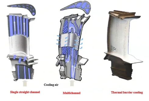
Cooling Strategies for High-Temperature Blades
In high-pressure stages of gas turbines, metal temperatures must be kept below material limits despite gas temperatures that can exceed the metal’s melting point. This is achieved with internal and external cooling systems.
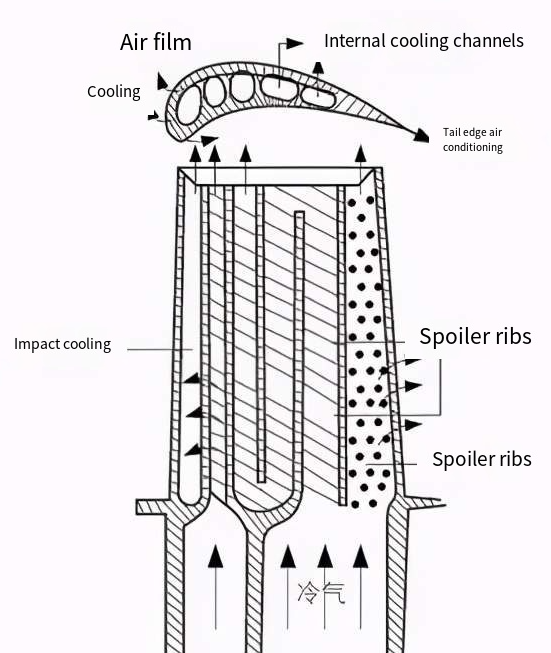
Internal Cooling Techniques
Internal cooling relies on relatively cooler air, usually extracted from the compressor, that flows through channels inside the blade. Common features include:
- Serpentine passages with multiple turns to increase heat transfer surface area
- Rib turbulators and pin fins to disturb boundary layers and enhance convection
- Leading-edge impingement cooling, where jets of air strike the hot surface from the inside
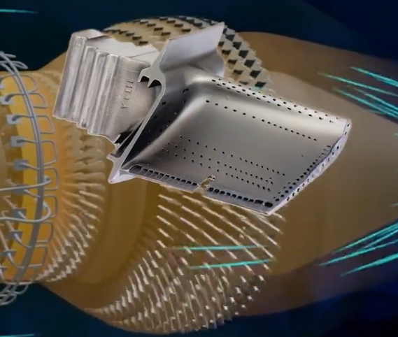
External Cooling Techniques
External cooling methods supplement internal cooling and protect the blade surface.
- Film cooling: Coolant air exits through small holes and forms a protective layer on the hot gas side.
- Trailing-edge cooling: Slots or holes at the trailing edge allow air to cool the thin trailing edge region.
- Thermal barrier coatings: Ceramic layers that reduce metal surface temperature and provide oxidation resistance.
The design of cooling systems balances cooling effectiveness, aerodynamic losses, and consumption of compressor bleed air, which reduces overall cycle efficiency if overused.
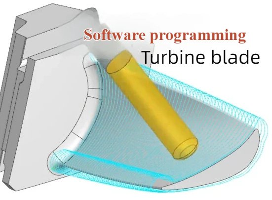
Manufacturing Methods for Turbine Blades
Manufacturing routes for turbine blades depend on material, geometry, and required performance characteristics. Production processes must provide high dimensional accuracy, surface quality, and structural integrity.
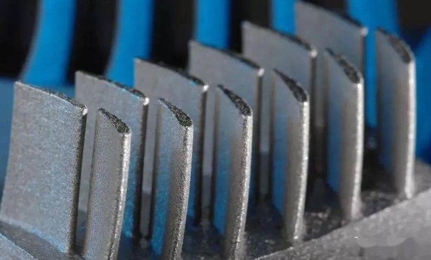
Casting and Solidification Techniques
High-temperature gas turbine blades are commonly produced by investment casting. This process allows complex shapes, including internal cooling channels, to be formed as a single piece.
Advanced casting techniques include:
- Equiaxed casting: Conventional casting with randomly oriented grains
- Directionally solidified casting: Solidification controlled to align grains along the main stress direction
- Single-crystal casting: Entire blade formed as a single crystal without grain boundaries
These techniques improve creep resistance, fatigue strength, and thermal fatigue performance at high temperatures.
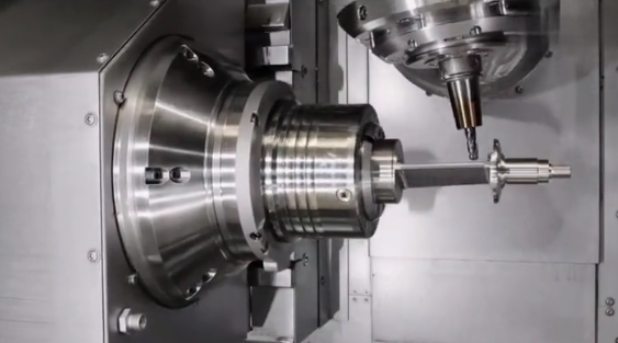
Forging, Machining, and Welding
Steam turbine and hydro turbine blades are often forged from steels and then machined to final profile. Large runner blades may be fabricated by welding plates and machined sections together, followed by extensive finishing operations.
Typical steps include:
- Open or closed-die forging of preforms
- Rough machining of root, platform, and airfoil
- Finish machining and grinding for aerodynamic accuracy
- Inspection by ultrasonic or dye penetrant testing
Wind turbine blades use composite fabrication methods such as hand layup, infusion, or pre-preg processes in molds, followed by bonding of shell halves, finishing, and surface coating.
Performance and Reliability Considerations
Turbine blade design and operation are strongly focused on achieving high efficiency and long, reliable service. Performance metrics are interlinked with mechanical integrity and maintenance requirements.
Efficiency and Aerodynamic Losses
Blade aerodynamic performance is evaluated based on:
- Stage efficiency and total-to-total or total-to-static efficiency
- Losses due to boundary layer growth, secondary flows, and tip leakage
- Incidence losses at off-design flow angles
Optimized blade profiles, surface finishes, and end-wall contouring help minimize losses and increase overall turbine efficiency.
Fatigue, Creep, and Damage Mechanisms
Major damage mechanisms affecting turbine blades include:
- High-cycle fatigue from vibratory loading
- Low-cycle fatigue from start-stop thermal and mechanical cycles
- Creep at elevated temperatures in gas and steam turbines
- Oxidation, hot corrosion, and erosion from particles or droplets
- Cavitation damage in hydro turbines
Mitigation approaches involve careful design margins, choice of materials and coatings, controlled operating conditions, and well-planned inspection and maintenance intervals.
Typical Applications of Turbine Blades
Turbine blades are integral components in many industrial and power-generation systems. The application determines the blade type, geometry, material, and associated design priorities.
| Application | Turbine Type | Key Blade Requirements |
|---|---|---|
| Gas-fired power plants | Industrial gas turbines | High-temperature capability, high efficiency, robust cooling, corrosion resistance |
| Combined-cycle power plants | Gas and steam turbines in tandem | Optimized hot gas and steam blades, complementary performance, long life |
| Aircraft propulsion | Turbojet, turbofan, turboprop engines | Low weight, high strength at elevated temperature, excellent fatigue and creep resistance |
| Industrial mechanical drives | Gas and steam turbines driving compressors or pumps | Reliability, wide operating envelope, resistance to fouling and corrosion |
| Hydroelectric power stations | Francis, Kaplan, Pelton turbines | Cavitation resistance, corrosion resistance, hydraulic efficiency, maintainability |
| Onshore wind farms | Horizontal-axis wind turbines | Lightweight composite blades, high fatigue resistance, easy transport and installation |
| Offshore wind farms | Large-scale wind turbines | High strength-to-weight, environmental resistance, optimized for marine conditions |
Pain Points and Practical Considerations in Turbine Blade Use
Engineers and operators face several practical considerations when selecting, operating, and maintaining turbine blades. Addressing these aspects is critical to achieving target performance and cost objectives.
Maintenance and Inspection Requirements
Turbine blades must be periodically inspected to detect wear, cracks, corrosion, and deformation. Typical inspection methods include visual inspection, borescope examination, non-destructive testing (such as ultrasonic, eddy current, and dye penetrant), and dimensional checks.
Frequent start-stop cycles, fuel quality, and environmental conditions influence inspection intervals. Predictive maintenance based on condition monitoring can help minimize unplanned outages.
Operating Conditions and Service Environment
Performance and lifetime are sensitive to the actual operating environment:
- Temperature margins and thermal gradients in gas and steam turbines
- Presence of solid particles, salts, or corrosive species in air, gas, or steam
- Water quality and oxygen content for hydro turbines
- Wind turbulence, gusts, and icing for wind turbine blades
Proper filtration, water treatment, and operational guidelines help reduce environmental damage to turbine blades.
Blade Replacement and Lifecycle Costs
Because turbine blades are high-value components, their replacement and refurbishment have a significant impact on lifecycle cost. Engineered repair processes such as welding, recoating, and dimensional restoration are often applied to extend blade life, particularly in gas and steam turbines.
Decision-making on repair versus replacement considers remaining life assessment, damage extent, material condition, and downtime costs.
FAQ About Turbine Blades
What is a turbine blade?
A turbine blade is a critical component of a turbine that converts the energy of a fluid (steam, gas, or water) into mechanical energy by rotating the turbine shaft. Turbine blades extract energy from a moving fluid to spin the turbine rotor, which then drives a generator or mechanical device, converting fluid energy into usable mechanical or electrical energy.
What are the key design considerations for turbine blades?
Design focuses on aerodynamics, material strength, temperature resistance, corrosion resistance, vibration tolerance, and fatigue life.
What industries use turbine blades?
Turbine blades are widely used in power generation (steam and gas turbines), aviation (jet engines), marine propulsion, and industrial gas turbines.
What common problems occur with turbine blades?
Common issues include erosion, corrosion, thermal fatigue, creep, and vibration damage, which can reduce efficiency or cause failure.
How is the performance of turbine blades tested?
Performance is evaluated through stress analysis, computational fluid dynamics (CFD) simulations, high-temperature testing, vibration analysis, and sometimes destructive testing for durability studies.
