
4 axis CNC machining is a computer-controlled manufacturing process in which cutting tools move along three linear axes (X, Y, Z) and one rotary axis (usually called the A axis). Compared with standard 3 axis machining, a 4 axis machine can rotate the workpiece or the tool around one axis, enabling more complex geometry, improved access to multiple faces of a part, and reduced setups.
Basic Concept of 4 Axis CNC
In a conventional 3 axis CNC machine, the tool moves in three perpendicular directions: X (left–right), Y (front–back), and Z (up–down). The workpiece remains fixed except for clamping and repositioning between operations. In 4 axis CNC machining, an additional rotary movement is added, typically around the X axis. This allows the machine to rotate the workpiece and perform operations on different sides without manual reclamping.
The additional rotary axis is most commonly referred to as the A axis when it rotates around the X axis. In some machine configurations, the fourth axis may rotate around the Y axis (called the B axis) or less frequently around the Z axis (called the C axis). However, most standard 4 axis vertical machining centers use an A axis rotary table.
This capability makes 4 axis CNC machining particularly useful for parts that require features on multiple sides, for machining cylindrical profiles, and for tasks like engraving on round surfaces or cutting helical shapes.
Axes Definitions and Kinematics
To understand 4 axis CNC machining, it is useful to define the linear and rotary axes and their typical functions.
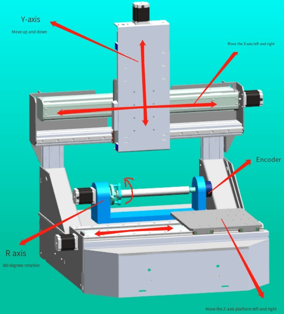
- X axis: Linear movement left and right, usually along the machine table width.
- Y axis: Linear movement front and back, perpendicular to the X axis.
- Z axis: Linear movement up and down, controlling the tool’s depth of cut.
- A axis: Rotary movement around the X axis (most common in 4 axis machining).
The machine’s kinematics define how these axes move relative to each other. In a typical 4 axis vertical machining center with a rotary table:
- The spindle moves in Z (up/down) and often in X and/or Y.
- The workpiece is clamped on a rotary table that can index or rotate continuously around the A axis.
4 axis CNC machines may support two distinct modes of rotary motion:
Indexed 4 axis machining: The A axis rotates the workpiece to a defined angle, then locks in place. Machining is then performed using 3 axis linear motion (X, Y, Z) with the part held at the chosen orientation. After completing operations at that angle, the A axis indexes to another angle, and the cycle repeats.
Continuous 4 axis machining: The A axis rotates simultaneously while linear axes move. This allows the tool to trace complex paths around the part, such as wrapping toolpaths around cylindrical surfaces or machining helical grooves. This is also called simultaneous or interpolated 4 axis machining.
Key Components of a 4 Axis CNC Machine
A typical 4 axis CNC machining system consists of mechanical, electrical, and software components designed to work together with high precision.
| Component | Primary Function |
|---|---|
| Machine base and column | Provide structural rigidity and support for all moving elements |
| Linear axes (X, Y, Z) | Enable positioning and feed motion of the cutting tool relative to the workpiece |
| Rotary axis (A, B, or C) | Rotate the workpiece (or tool) to specific angles or continuous positions |
| Spindle | Holds and rotates the cutting tools at controlled speeds |
| Rotary table or indexer | Mechanism that provides precise rotary motion and workholding on the fourth axis |
| Drive systems | Servo or stepper motors plus ball screws or direct drives for axis motion |
| Feedback systems | Encoders and scales for position and speed feedback to the CNC control |
| CNC control unit | Interprets programs (G-code), coordinates motion, and manages machine functions |
| Tool changer (if equipped) | Automatically exchanges cutting tools to reduce manual intervention |
| Coolant and chip management | Delivers coolant to the cutting zone and removes chips from the work area |
| Workholding fixtures | Secure the part to the rotary table or indexing device |
In many installations, the fourth axis is added as an accessory rotary table or indexer mounted on the standard machine table. In others, the rotary axis is integrated into the machine design. Integrated configurations are often more rigid and accurate, while add-on rotary tables provide flexibility to switch between 3 and 4 axis work.
Types of 4 Axis CNC Machines
Different mechanical layouts are used to implement 4 axis capability. The main types include:
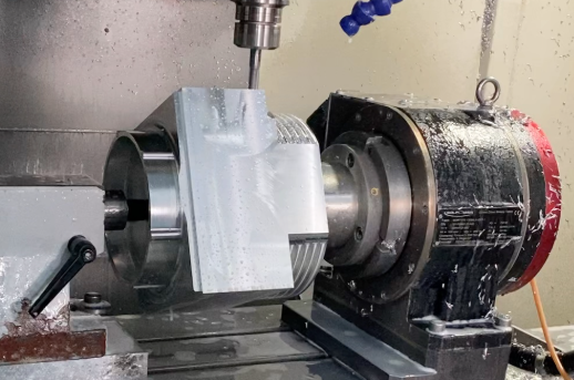
4 axis vertical machining centers (VMC): The most common configuration. The spindle is vertical, and the rotary A axis is typically a table mounted on the main machine table. The workpiece is clamped to the rotary table, which can index or rotate continuously. This arrangement is widely used for prismatic parts and general machining.
4 axis horizontal machining centers (HMC): The spindle is horizontal, and the workpiece is often mounted on a rotary table that may also support a pallet system. Horizontal machines with a fourth axis are well suited for multi-face machining of parts, since chips fall away from the cutting area due to gravity, and several sides of a part can be accessed efficiently through rotation.
4 axis CNC milling machines with add-on rotary tables: In some cases, a conventional 3 axis milling machine is upgraded by adding a rotary table driven by an additional axis channel in the CNC control. This can be a cost-effective approach when occasional 4 axis work is required.
4 axis CNC routers: In woodworking, plastics machining, and light metal machining, 4 axis CNC routers are used to machine long or complex shapes. The rotary axis may be implemented as a rotating spindle (for machining along the length of a workpiece) or as a rotary fixture for cylindrical or decorative work.
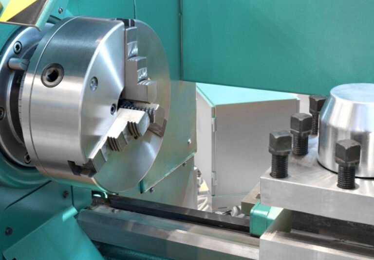
4 axis CNC lathes with live tooling: Some turning centers can be considered 4 axis when they combine X and Z linear axes with a C axis spindle rotation and a Y or other linear axis, enabling milling operations around the turned part. However, in many classifications these are counted separately as mill-turn or multitasking machines.
Linear and Rotary Axis Parameters
When evaluating or operating a 4 axis CNC machine, several technical parameters define its capability and performance. Typical values vary by machine size, build quality, and application, but key parameters include axis travel ranges, rotational limits, speed capabilities, and accuracy specifications.
| Parameter Category | Examples of Specific Parameters |
|---|---|
| Linear axes (X, Y, Z) | Travel range (e.g., X: 600 mm, Y: 400 mm, Z: 400 mm); Rapid traverse rate (e.g., 24–48 m/min); Maximum feed rate (e.g., up to 15 m/min); Positional accuracy (e.g., ±0.005–0.01 mm); Repeatability (e.g., ±0.003–0.005 mm) |
| Rotary axis (A) | Rotation range (e.g., ±110°, ±120°, 0–360° continuous); Maximum rotational speed (e.g., 20–50 rpm for heavy tables, higher for smaller units); Indexing accuracy (e.g., ±5–15 arc seconds); Clamping torque (e.g., several hundred to several thousand N·m) to resist cutting forces |
| Spindle | Speed range (e.g., 6,000–15,000 rpm for many VMCs; higher for high-speed machining); Power rating (e.g., 7.5–30 kW); Maximum torque (e.g., 50–200 N·m depending on spindle design) |
| Tool system | Tool taper interface (e.g., BT40, CAT40, HSK63); Tool magazine capacity (e.g., 16–60 tools); Maximum tool length and diameter |
| Control and interpolation | Number of simultaneously controllable axes (4 or more); Minimum program increment (e.g., 0.001 mm or 0.0001 mm); Look-ahead and interpolation functions for smooth motion |
These parameters directly influence what size of part can be machined, how fast operations can be performed, and what level of accuracy can be achieved. When selecting a 4 axis machine for a specific task, the required travel, rotary range, and accuracy should be compared to the part geometry and tolerance specifications.
How 4 Axis CNC Machining Works
4 axis CNC machining follows a structured workflow from design to final part. The presence of the rotary axis changes the way parts are fixtured, programmed, and executed but the overall process remains systematic and repeatable.
1) Design and CAD Modeling
The process starts with a digital representation of the part, usually created in CAD (Computer-Aided Design) software. The model should include all features that will be machined, including those on multiple sides or around cylindrical surfaces. For 4 axis machining, it is useful to think about how the part will be oriented on the rotary axis early in the design stage to ensure that all necessary surfaces can be reached.
2) CAM Programming and Toolpath Generation
CAM (Computer-Aided Manufacturing) software is used to convert the CAD model into machine instructions. With 4 axis capability, CAM systems provide additional strategies compared to 3 axis machining, such as:
- Indexed multi-face machining: The part is rotated to a series of fixed angles (for example, 0°, 90°, 180°, 270°). For each angle, standard 3 axis toolpaths are generated. The CAM software outputs rotary positioning commands between operations.
- Rotary or wrapped machining: Toolpaths designed on a flat plane are mathematically wrapped around a cylindrical surface. This is suited to engraving, slots, or pockets that follow a circular path around the workpiece.
- Simultaneous 4 axis machining: The CAM system calculates toolpaths where the A axis rotates while X, Y, and Z move at the same time. This is used for helical grooves, screw-like features, and certain sculpted surfaces.
Toolpath strategies must consider collision avoidance, axis limits (such as maximum rotation range), and the orientation of the tool relative to the workpiece surface. Post-processing within the CAM software translates these strategies into G-code that matches the specific 4 axis machine and control unit.
3) Workholding and Setup
Secure workholding is essential for 4 axis machining. The workpiece is typically mounted on a rotary table, chuck, collet, or dedicated fixture attached to the A axis. Key setup considerations include:
- Alignment: The rotational axis of the A axis should be aligned with the part’s centerline when the part is intended to rotate concentrically.
- Clamping: Fixtures must withstand cutting forces in all orientations as the part rotates.
- Access: The clamping method should allow the cutting tool to reach all required surfaces without interference.
Reference points (work offsets) are set using probes or manual touch-offs. The position of the part relative to the machine coordinate system and the rotary zero position must be accurately defined to ensure correct indexing and rotation.
4) G-Code and CNC Control Execution
Once the program is loaded into the CNC control, the machine executes the instructions automatically. Typical G-code for 4 axis machining includes commands for:
- Linear motion (G00 rapid, G01 feed moves)
- Circular interpolation in linear planes (G02, G03)
- Rotary axis positioning (e.g., A90. for 90-degree rotation)
- Simultaneous movements where A, X, Y, and Z change together along a toolpath
The control continuously coordinates all active axes to maintain the specified path, feed rate, and surface finish. Feedback from encoders ensures that the actual axis positions closely match the programmed positions. High-performance controls may also perform look-ahead calculations to avoid abrupt changes in speed or direction that could degrade surface quality.
Typical Applications of 4 Axis CNC Machining
4 axis CNC machining is used in many industries where parts have features on multiple sides, cylindrical geometry, or helical and spiral shapes. Some common application areas include:
General mechanical components: Shafts, flanges, brackets, and housings often require machining on several faces. 4 axis machining can handle drilling, tapping, and milling around the circumference or on multiple sides without re-fixturing.
Automotive components: Manifolds, gear housings, and various engine or transmission parts can benefit from indexed multi-face machining. The rotary axis allows machining of ports, holes, and pockets at precise angular positions.
Aerospace components: Many aerospace parts require tight tolerances and complex features around cylindrical or multi-sided geometries. 4 axis capability supports accurate positioning of features and efficient machining of components like structural brackets or small turbine-related parts.
Medical devices: Implants, surgical tools, and orthopedic components often involve contoured surfaces and features around circular sections, where 4 axis machining helps achieve precise shapes and consistent quality.
Molds and tooling: For some mold inserts and tooling components, 4 axis machining allows side features, cooling channels, or angled details to be machined without dismantling and reclamping the part.
Engraving and decorative work: Logos, text, and patterns can be engraved around cylindrical items such as handles, knobs, and rings using rotary engraving toolpaths.
Advantages of 4 Axis CNC Over 3 Axis
Adding a fourth axis provides several practical benefits compared to standard 3 axis machining, especially for parts with geometry distributed around a rotational axis.
Improved access to multiple faces: With a rotary axis, the machine can present different sides of the part to the tool automatically. This reduces or eliminates manual repositioning, especially for prismatic parts with features on several faces.
Reduced setups and higher consistency: When multiple faces are machined in a single setup, the relative position of features is controlled by the machine’s axes rather than by manual re-clamping. This typically improves dimensional consistency between features located at different angles or sides.
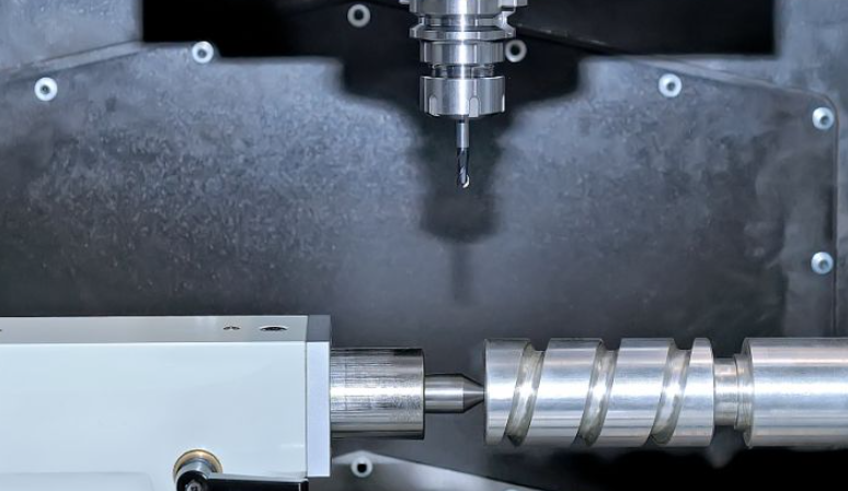
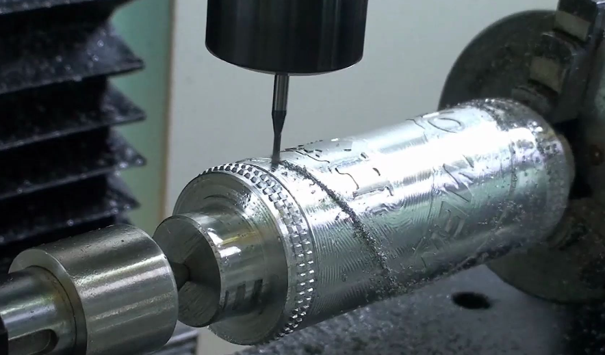
Efficient machining of cylindrical and radial features: 4 axis machining is well-suited for operations around cylindrical parts, such as cutting slots, flats, keyways, and helical grooves. Wrapped toolpaths and continuous rotation can produce these features more efficiently and accurately than alternative methods.
Potential time savings: Fewer setups and automated indexing can shorten overall production time for suitable parts. The machine can perform operations sequentially at different angles without operator intervention, which is beneficial in batch or repetitive machining.
Enhanced geometric capability: While still simpler than full 5 axis machining, 4 axis capability extends what can be machined beyond the limits of 3 axis. It enables complex patterns and multi-face features that would otherwise require manual repositioning or additional specialized equipment.
Comparison: 4 Axis vs 3 Axis vs 5 Axis CNC
To place 4 axis CNC machining in context, it is useful to compare it with 3 axis and 5 axis machines.
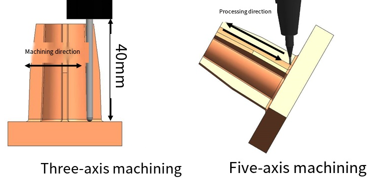
3 axis CNC: The machine moves only in X, Y, and Z. All features must be reachable from a single direction or through manual re-fixturing. This configuration is widely used for flat or prismatic parts, simple 3D contours, and general machining. It is usually the most economical option in terms of machine cost and programming complexity.
4 axis CNC: Adds one rotary axis, typically rotating the workpiece around X (A axis). This system is suitable for parts that have features around a single rotational axis or on multiple side faces that can be accessed by rotation. It provides more capability than 3 axis machines without the full complexity of 5 axis systems.
5 axis CNC: In addition to three linear axes, these machines have two rotary axes. This allows the tool to approach the workpiece from many directions and maintain optimal orientation relative to the surface. 5 axis machining is used for highly complex parts such as turbine blades, impellers, and molds with undercuts. It is more capable but typically more expensive and more demanding in terms of programming and setup.
In situations where all required features are distributed around a single axis and there are no severe undercuts or complex compound angles, 4 axis machining often provides a practical middle ground between capability and cost.
Programming Considerations for 4 Axis CNC
Programming for 4 axis CNC machining introduces specific considerations beyond those for 3 axis machining, particularly in the treatment of the rotary axis and the management of part orientation.
Coordinate systems and work offsets: The programmer must define how the part coordinate system relates to the machine axes and the rotary zero position. When the part is rotated, the coordinate system orientation changes. Modern CAM software manages this automatically, but the mapping between virtual setups in the software and physical setups on the machine must be consistent.
Angular positions and indexing: For indexed machining, the programmer defines angular positions (for example A0, A90, A180, A270) corresponding to different faces. The CAM software groups toolpaths by index angle, and the post-processor outputs rotary moves between groups. These angular values must match the actual orientation of the part in the fixture.
Wrapped toolpaths: When machining around cylindrical surfaces, the programmer may use a wrap function that converts linear coordinates into angular coordinates. For example, a pattern defined along a linear axis in the CAD model is wrapped onto a cylinder of specified diameter. The CAM software handles the mathematical transformation so the resulting G-code commands the rotary axis appropriately.
Simultaneous motion and feed control: In continuous 4 axis machining, linear and rotary movements occur together. The effective cutting speed along the surface depends on both rotational and linear components. CAM systems and CNC controls manage this by calculating appropriate feed rates, but programmers should verify that programmed feeds are suitable for the combined motion to maintain proper chip load and surface finish.
Collision and limit checks: As the part rotates, tool, holder, and fixture can interact in complex ways. Programmers should use simulation tools to check for collisions and to ensure that rotary axis limits (maximum angle, rotational clearance) are not exceeded. This step is particularly important when tall fixtures or long tools are used.
Accuracy and Surface Quality in 4 Axis Machining
Accuracy and surface quality depend on mechanical rigidity, control quality, tool selection, and proper setup. The presence of a rotary axis adds specific factors that influence final results.
Rotary axis indexing accuracy: When using indexed 4 axis machining, the angular accuracy of the A axis determines how precisely features on different faces align. Indexing accuracy is typically specified in arc seconds. A smaller value indicates better precision. Any error in indexing manifests as angular misalignment that can cause position errors and mating issues in assemblies.
Rotary clamping rigidity: Many rotary tables include a clamping mechanism that locks the axis during cutting. Adequate clamping torque is important to prevent micro-movements under cutting forces, which could deteriorate surface finish and dimensional accuracy. For continuous 4 axis machining, the drive and feedback system must also be capable of smooth and stable motion.
Tool runout and deflection: As with all CNC machining, cutting tools must be properly balanced and held with minimal runout to maintain precision. Tool deflection may vary with part orientation and direction of force, so depth of cut and feed should be selected considering the stiffness of the setup at each angle.
Thermal stability: Prolonged machining can cause temperature changes in the machine structure and rotary table. These changes may slightly affect positioning accuracy. Good machine design, warm-up routines, and stable ambient conditions help reduce thermal effects.
Surface finish: For rotary or simultaneous operations, surface finish can be influenced by the synchronization between rotary and linear movements, step-over parameters, and the rotational speed of the A axis. Smooth interpolation, appropriate step-over, and correct feed/speed settings generally result in uniform surface texture.
Material Compatibility and Tooling Considerations
4 axis CNC machining supports a wide range of materials, including metals, plastics, composites, and wood. The choice of material and application determines the required tooling, cutting parameters, and coolant strategy.
Metals: Steel, stainless steel, aluminum, brass, titanium, and other alloys can be machined with 4 axis systems. Rotary operations such as milling around shafts or machining helical grooves are common in metalworking. Tools are typically carbide or high-speed steel with coatings matched to the material and cutting conditions.
Plastics and composites: Engineering plastics and composite materials can also be machined. For these materials, cutting parameters are chosen to minimize heat build-up, burr formation, and delamination. Router-style 4 axis machines are often used for large plastic or composite components.
Wood: In woodworking, 4 axis CNC routers carve, profile, and engrave around cylindrical or irregular wooden workpieces. Specific tooling and dust extraction solutions are used to handle wood chips and dust.
Tool selection: Tools must be chosen not only for material compatibility but also for the geometry of the operation. For example, ball nose end mills are often used for wrapping toolpaths around cylindrical surfaces where smooth transitions are required, while flat end mills or slot drills are used for flats and keyways on shafts.
Workholding and Fixturing for 4 Axis CNC
Effective fixturing is crucial to fully utilize 4 axis capabilities. A suitable fixture ensures that the part remains secure and accurately positioned at all rotary angles.
Rotary chucks and collets: For round or shaft-like parts, standard chucks, collets, or mandrels are used. The part is aligned with the rotary axis, enabling concentric rotation and uniform machining around the circumference.
Dedicated fixtures: For irregular or prismatic parts, custom fixtures or modular fixturing systems are mounted on the rotary table. These fixtures are designed to clamp the part firmly while providing clearance for the tool at all required angles.
Counterbalancing: When parts or fixtures are heavy or asymmetrical, the rotary axis may be subject to uneven loads. Some setups require counterweights or balanced fixture designs to minimize vibration and load on the rotary bearings and drive system.
Access planning: Fixturing should consider tool access paths to avoid interference. High clamping elements or bulky fixture components should be placed where they do not obstruct the tool in any indexed or continuous position needed for machining.
Safety and Operational Considerations
Operating a 4 axis CNC machine requires attention to safety and operational procedures, especially because parts and fixtures rotate and may present additional hazards compared with purely linear machines.
Rotating components: The rotary table, chucks, and attached parts can rotate at significant speed. All operators must keep clear of rotating components and ensure that workpieces and fixtures are properly secured before machining starts. Loose items or unbalanced loads can create safety risks and damage the machine.
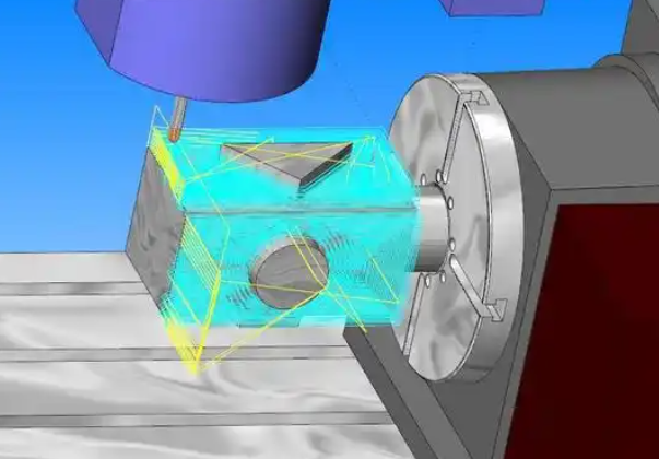
Program verification: Because 4 axis movements are more complex than simple 3 axis operations, program verification through dry runs, single-block execution, and simulation is recommended. This reduces the risk of collision and unexpected axis motion.
Limit switches and soft limits: Machines typically include hardware and software limits for the rotary axis to prevent over-rotation or mechanical interference. Proper setup of soft limits and verification of their correctness helps safeguard the machine during programming and operation.
Monitoring: During operation, monitoring spindle load, axis load, and abnormal vibrations can help detect issues early, such as tool wear, fixture loosening, or incorrect feed settings. Corrective measures can then be taken before part quality is compromised or damage occurs.
When 4 Axis CNC Is an Appropriate Choice
4 axis CNC machining is most appropriate in situations where the geometry of the part or the production requirements align with the capabilities of an additional rotary axis.
Parts with symmetric features around a central axis: Components such as shafts with flats, radial holes, keyways, and slots can be efficiently machined on a 4 axis machine. The part remains clamped while the machine rotates it to reach all required features.
Parts requiring machining on several side faces: Blocks or housings needing operations on four sides can often be machined in a single setup using indexed angles. This improves alignment and reduces handling time compared with multiple 3 axis setups.
Batch and repetitive production: For parts that are produced repeatedly, investing time in a well-designed 4 axis fixture and program can yield substantial efficiency gains over multiple runs, as setups are simplified and cycle times are reduced.
Complex cylindrical engraving or profiling: Logos, patterns, and contours that must follow cylindrical or spiral paths are particularly suited to continuous 4 axis machining, especially when consistent quality is required across many identical parts.
Limitations and Considerations of 4 Axis CNC
While 4 axis CNC machining extends the capabilities of 3 axis systems, there are practical limitations and considerations that should be recognized.
Geometric constraints: 4 axis machines can rotate around only one axis. If a part requires features that must be approached from many different orientations or has deep undercuts in multiple directions, 4 axis may not be sufficient, and 5 axis or other solutions might be required.
Setup complexity: Although 4 axis machining can reduce the number of setups for production, the initial setup and fixturing for a 4 axis job can be more complex than for a standard 3 axis job. Accurate alignment with the rotary axis and proper fixture design require careful planning.
Programming and verification effort: 4 axis programs are more complex than 3 axis programs. Additional time may be needed for programming, simulation, and verification, especially for simultaneous 4 axis toolpaths. This effort should be considered when evaluating the overall productivity of a 4 axis solution.
Rotary axis capacity: Rotary tables have limits for maximum workpiece weight, size, and overhung load. For very large or very heavy parts, the rotary axis may not be capable of safely supporting or rotating the workpiece, even if the linear axes have sufficient travel.
Machine cost relative to needs: 4 axis machines and rotary tables typically cost more than standard 3 axis machines. If the majority of work only requires simple faces or flat surfaces, the additional capability may not be fully utilized. Evaluating the mix of parts and their geometries helps determine if 4 axis investment is justified.
FAQ About 4 Axis CNC Machining
What is the difference between 4 axis and 5 axis CNC machining?
4 axis CNC machining adds a single rotary axis to the three standard linear axes, allowing the workpiece (or tool) to rotate around one axis. This enables multi-face machining and operations around cylindrical parts. 5 axis CNC machining includes two rotary axes in addition to the three linear axes, allowing the tool to tilt and rotate in more directions. 5 axis machines can access more complex geometries and undercuts, and maintain optimal tool orientation to the surface, but they are generally more complex and costly than 4 axis systems.
When should I choose a 4 axis CNC machine instead of a 3 axis machine?
A 4 axis CNC machine is a good choice when your parts require features around a single rotational axis or on multiple side faces that can be reached by rotating the part. Examples include shafts with keys or flats, blocks with holes on several sides, and cylindrical parts with engraving or slots. If most of your work involves only flat surfaces and features that can be reached from a single direction, a 3 axis machine may be sufficient. If you frequently need to reposition parts manually to reach different faces, 4 axis capability can significantly reduce setups and improve alignment between features.
Can a 4 axis CNC machine perform simultaneous rotary and linear cutting?
Yes, many 4 axis CNC machines support simultaneous rotary and linear movements. In this mode, the rotary axis (such as A) and the linear axes (X, Y, Z) move together while cutting. This is used for operations like machining helical grooves, spiral profiles, and wrapped toolpaths around cylinders. The CNC control and CAM software must both support 4 axis interpolation to generate and execute these continuous toolpaths correctly.
What types of parts are best suited for 4 axis CNC machining?
Parts that are best suited for 4 axis CNC machining include components with features distributed around a central axis, such as shafts with slots, flats, or radial holes; prismatic parts that require machining on several side faces; cylindrical components with engraving or patterns; and parts that need helical or spiral grooves. These geometries leverage the rotary capability to reduce multiple setups and improve positional accuracy between features located at different angles.
What is 4-axis CNC machining?
4-axis CNC machining is a process where the cutting tool moves along the traditional X, Y, and Z linear axes, with an additional rotary axis (A-axis) that allows the workpiece to rotate, enabling machining around cylindrical or complex geometries.
