
3-axis CNC refers to computer numerically controlled machining where the tool or workpiece moves along three linear axes: X, Y, and Z. It is one of the most widely used configurations in manufacturing for milling, drilling, and cutting operations, balancing capability, cost, and complexity.
Basic Concept of 3-Axis CNC Machining
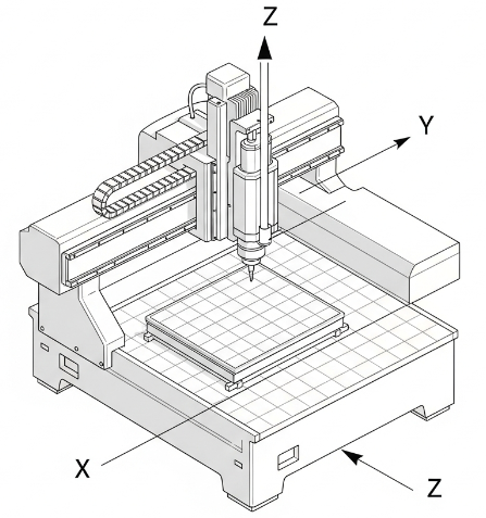
3-axis CNC machining is a subtractive manufacturing process in which a cutting tool removes material from a stationary or moving workpiece along three orthogonal directions:
- X-axis: left–right (usually table or tool movement horizontally)
- Y-axis: front–back (perpendicular horizontal movement)
- Z-axis: up–down (vertical movement)
All movements are controlled by a CNC controller that interprets a part program (commonly G-code). The controller commands servo or stepper motors to position the tool and workpiece with high accuracy.
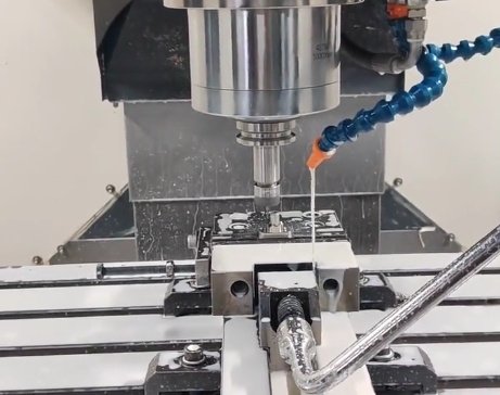
In a typical 3-axis CNC milling center, the tool rotates and moves in X, Y, and Z directions while the workpiece is clamped to a fixed table. The machine removes material layer by layer according to the programmed toolpaths to form the desired geometry.
Key Components of a 3-Axis CNC Machine
A 3-axis CNC machine is a system composed of mechanical, electrical, and control subsystems. Understanding these components helps with specification, setup, and operation.
Mechanical Structure
The mechanical structure provides rigidity and precision for cutting operations. Common configurations include:
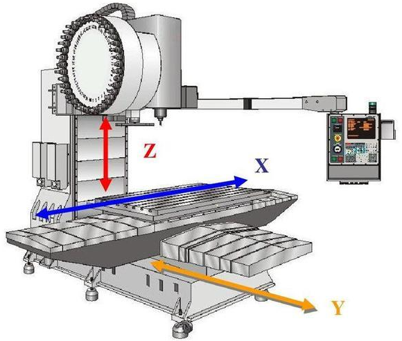
- Vertical machining center (VMC): spindle is vertical; the table moves in X and Y, and the spindle moves in Z.
- Horizontal machining center (HMC): spindle is horizontal; the table usually moves in X and Z, and the column or saddle moves in Y.
- Gantry or portal-type machines: a bridge spans over the worktable, suitable for large workpieces.
Core structural elements include bed, column, saddle, table, and spindle head. These are often made from cast iron or welded steel to provide stiffness and damping.
Linear Axes and Motion System
Each axis consists of guides and a drive mechanism:
- Linear guides: box ways or linear guideways that support motion and resist cutting forces.
- Ball screws or linear motors: convert rotary motion to linear motion with low backlash and high efficiency (ball screws are most common in 3-axis machines).
Typical features include:
- Axis travel ranges: from around 200–300 mm on small machines to over 1500 mm or more on large machining centers, depending on model and application.
- Rapid traverse speeds: frequently in the range of 10–60 m/min, allowing fast repositioning without cutting.
- Feed rates: commonly up to 5–20 m/min in cutting, depending on material, tool, and machine.
Spindle System
The spindle holds and rotates the cutting tool. Spindle characteristics strongly influence productivity and achievable surface finish. Typical parameters include:
| Parameter | Common Range | Notes |
|---|---|---|
| Power | 3–40 kW | Low-power for light machining; high-power for heavy milling |
| Speed | 3,000–24,000 rpm | Higher speeds for aluminum, plastics; lower for steel |
| Taper type | BT, CAT, HSK, ISO | Affects tool rigidity and change time |
| Drive | Belt, direct, or built-in motor | Direct/built-in often provide better dynamics |
Spindles can be equipped with cooling (air or liquid) and often integrate sensors for load monitoring and spindle orientation.
Control System and CNC Unit
The CNC control unit is the “brain” of the machine. Core functions include:
- Interpreting G-code and M-code instructions.
- Coordinating axis movement with spindle rotation.
- Managing tool changes, coolant, and auxiliary functions.
- Handling coordinate systems, tool length and radius compensation, and offsets.
Common features of industrial 3-axis controls:
- Interpolated control across all three axes for complex contours.
- Look-ahead functions to maintain smooth tool motion.
- Various operating modes such as automatic (program run), manual jog, and MDI (manual data input).
Tool Changer and Tooling System
Many 3-axis machining centers include an automatic tool changer (ATC). Common aspects include:
- Tool magazine capacity: frequently 10–60 tools or more, depending on machine size.
- Tool length and diameter measurement: either manual presetting or automatic tool measurement probes.
- Tool standards: BT30, BT40, BT50, CAT40, HSK63, etc.
Tooling encompasses end mills, drills, taps, face mills, and specialty cutters, selected according to material and required geometry.
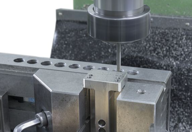
Workholding and Fixtures
Workholding devices keep the workpiece stable under cutting forces. Typical solutions include:
- Machine vises.
- Clamping kits (step blocks, T-slot clamps).
- Modular fixturing plates and grids.
- Dedicated jigs and fixtures for higher-volume production.
For 3-axis machining, correct orientation of the workpiece is important because machining access is limited to a single setup orientation unless the part is re-clamped.
Coolant and Chip Management
Coolant systems supply cutting fluid to reduce tool wear, improve surface finish, and flush chips away:
- Flood coolant: nozzles direct a continuous flow to the cutting zone.
- Through-spindle coolant: coolant passes through the tool body, especially useful for drilling.
- Air blast or minimum quantity lubrication (MQL): used when wet machining is not desired.
Chip conveyors or screw-type chip augers remove chips from the working area to maintain consistent machining conditions.
How 3-Axis CNC Machining Works
The workflow of 3-axis CNC machining begins with design and proceeds through programming, setup, and cutting.
CAD Model and Design
A 3D CAD model or 2D drawing defines the target geometry. The designer specifies dimensions, tolerances, surface finish requirements, and material. For simple parts, a 2D drawing with clear views may be sufficient; more complex profiles are typically fully modeled in 3D.
CAM Programming and Toolpath Generation
CAM (Computer-Aided Manufacturing) software generates the toolpaths used by the CNC machine. Key CAM steps include:
- Importing or creating the model.
- Selecting machine, tools, and material.
- Defining operations (e.g., facing, roughing, finishing, drilling, tapping, contouring, pocketing).
- Setting cutting parameters: spindle speed, feed rate, depth of cut, step-over, and approach/exit paths.
- Simulating toolpaths to check for collisions and ensure adequate material removal.
The CAM software outputs a G-code file tailored for the machine’s specific control.
G-Code and CNC Control
G-code instructs the machine in a structured way, specifying motion, speed, and auxiliary functions. Typical commands include:
- G00: rapid positioning.
- G01: linear interpolation (controlled feed move).
- G02/G03: circular interpolation (clockwise/counterclockwise arcs).
- G17/G18/G19: selection of machining plane.
- G54–G59: work coordinate systems.
- M03/M04: spindle on (clockwise/counterclockwise).
- M05: spindle stop.
- M08/M09: coolant on/off.
The CNC control interprets these commands, interpolates motion along X, Y, and Z axes, and coordinates with spindle rotation and tool changes.
Machine Setup and Work Offsets
Before machining can start, setup steps include:
- Installing the required tools in the magazine or spindle.
- Measuring tool lengths and, if necessary, diameters.
- Clamping the workpiece securely on the machine table using a vise, fixture, or clamps.
- Establishing a work coordinate system (e.g., G54) by probing or manually setting a reference point on the workpiece (such as a corner or hole center).
Accurate setup ensures that the toolpaths align with the actual position of the workpiece, enabling consistent dimensional accuracy.
Machining Operations on 3 Axes
Once setup is complete, the program is executed. Typical operations include:
- Facing: creating a flat surface to establish a reference plane.
- Roughing: removing bulk material using higher depth of cut and step-over.
- Finishing: applying smaller step-over and depth of cut to achieve final dimensions and surface finish.
- Drilling and tapping: creating holes and threads, often in predefined patterns.
- Contouring and pocketing: machining internal cavities or external profiles along 2D or 2.5D paths.
The CNC automatically controls feed and speed, but the operator monitors chip formation, tool wear, and machine behavior.
Capabilities and Typical Use Cases
3-axis CNC machines provide a practical solution for a broad range of parts. Their capabilities are determined by axis travel, spindle power, rigidity, and control features.
Suitable Part Geometries
3-axis CNC is well-suited for parts with:
- Features that can be accessed from a single side or from a few re-clamp positions.
- Flat surfaces, pockets, slots, holes, and 2.5D contours.
- Prismatic shapes like housings, brackets, plates, and blocks.
While complex 3D surfaces can be machined via 3-axis, accessibility and tool orientation are limited to one direction per setup.
Typical Industries and Applications
Common application areas include:
- General mechanical components: mounting plates, fixtures, frames, and machine parts.
- Automotive components: brackets, engine covers, housings, and mold bases.
- Aerospace secondary parts: fixtures, tooling, and some structural components with 2.5D features.
- Electronics: heat sinks, enclosures, and connector housings.
- Mold and die base machining: plates, pockets, and standard mold features.
- Education and prototyping: training centers and small-batch production in workshops.
Materials Machined on 3-Axis CNC
3-axis CNC machines can process a wide range of materials, including:
- Metals: aluminum alloys, steels (mild and alloy), stainless steels, copper, brass, and some titanium components depending on machine rigidity.
- Plastics: ABS, POM, nylon, polycarbonate, acrylic, and engineering plastics.
- Composites: carbon fiber-reinforced plastics (CFRP) and glass fiber composites, with appropriate tooling and dust management.
- Non-metallic materials: wood, foams, and modeling boards.
Technical Specifications and Performance Parameters
When evaluating or using a 3-axis CNC machine, several technical parameters are important for performance, precision, and suitability.
Axis Travel and Work Envelope
The work envelope defines the maximum part size that can be machined. Typical ranges (approximate) include:
- X-axis: 300–1600 mm or more.
- Y-axis: 200–800 mm or more.
- Z-axis: 200–700 mm or more.
In addition, the distance from spindle nose to table and the table size determine the maximum workpiece height and clamping options.
Accuracy and Repeatability
Precision is characterized by positioning accuracy and repeatability:
- Positioning accuracy: often in the range of ±0.005–±0.02 mm over full travel, depending on machine class.
- Repeatability: typically better than accuracy, often ±0.002–±0.01 mm.
Contributing factors include ball screw quality, encoder resolution, thermal stability, and mechanical stiffness. Calibration, compensation tables, and regular maintenance help maintain these values over time.
Feed Rates and Cutting Performance
Feed capability affects productivity:
- Rapid traverse rate: fast non-cutting positioning, often 20–60 m/min on modern machines.
- Cutting feed rate: typically up to 5–20 m/min, limited by tool, material, and spindle power.
Higher feed rates are used for softer materials and high-speed machining, while tougher materials require lower feeds and deeper engagement control.
Tool Capacity and Change Time
Automatic tool changers differ by:
- Capacity: small machines may hold 8–12 tools; larger machining centers may hold 20–60 or more.
- Tool change time: common values are in the range of 1–5 seconds per tool change.
More tools and faster change times allow for complex multi-operation parts without manual intervention.
Control Features and Programming Support
Beyond basic functions, control systems may offer:
- Multiple work coordinate systems (G54–G59, extended offsets).
- Tool radius and length compensation for precise contouring.
- Subroutines and macros to reuse program logic and simplify drilling patterns or repetitive features.
- Probing cycles for automatic workpiece and tool measurement.
Advantages of 3-Axis CNC Machining
3-axis CNC machining offers a combination of capability, cost, and simplicity suitable for many manufacturing environments.
Balance of Capability and Investment
Compared with more complex multi-axis machines, 3-axis systems:
- Have lower acquisition and operating costs.
- Are easier to program and set up for many standard parts.
- Provide sufficient functionality for a large percentage of prismatic components.
This makes them attractive for small to medium-sized workshops, educational institutions, and production lines focused on 2D and 2.5D parts.
High Repeatability for Standard Parts
3-axis CNC machines are highly effective for repeat production of standardized parts. Once a stable process is implemented, the combination of fixed fixturing, validated programs, and controlled tooling enables consistent batch quality with minimal manual intervention.
Integration with CAM and Digital Workflows
Most CAM systems natively support 3-axis strategies, such as adaptive roughing and contour finishing. The digital workflow from CAD to CAM to CNC allows:
- Standardized tool libraries and machining templates.
- Simulation of machining operations to reduce setup risk.
- Easy modification of programs when design changes occur.
Limitations and Practical Considerations
Despite their wide applicability, 3-axis CNC machines have inherent restrictions due to their kinematic structure and access directions.
Geometric and Access Limitations
Since the tool orientation is fixed relative to the workpiece in any given setup (only translation along X, Y, Z), certain geometries are difficult or impossible to machine in one clamping:
- Undercuts and features obscured from the top cannot be reached without special tooling or additional setups.
- Complex freeform surfaces that require tool tilting may need multiple orientations or different equipment.
- Deep cavities with limited tool reach can lead to deflection and poor surface quality.
As a result, some parts must be split into multiple operations with re-clamping, which can affect accuracy between features on different sides.
Setup and Fixturing Effort
To machine multiple sides of a part on a 3-axis machine, the operator often needs to:
- Re-clamp the workpiece in different orientations.
- Re-establish work offsets after each re-clamping.
- Control cumulative positioning error across setups.
While this is manageable for many parts, it increases setup time and requires careful workholding design to maintain dimensional consistency.
Rigidity and Vibration Considerations
Machine rigidity must be sufficient to handle cutting forces with minimal deflection:
- Large overhangs in tools or workpieces increase susceptibility to vibration.
- Light machines or worn guideways can result in chatter, dimensional error, and poor surface finish.
For demanding materials or aggressive cutting parameters, machine selection and setup must account for these mechanical aspects.
3-Axis CNC vs Other CNC Configurations
Understanding where 3-axis CNC stands in relation to other machine types helps with equipment selection.
3-Axis vs 2-Axis Machines
2-axis machines, such as some basic milling or turning systems, allow motion in only two directions. 3-axis machining provides an additional degree of freedom, enabling:
- Pocketing and 3D contours that are impossible with only X and Y motions.
- Machining of angled features by using Z-axis depth control.
For most milling tasks beyond very simple slotting or drilling, 3-axis capability is the baseline requirement.
3-Axis vs 4-Axis and 5-Axis Machines
4-axis and 5-axis machines add rotational motion (e.g., around A, B, or C axes). These additional axes allow:
- Machining on multiple sides of the part in a single setup.
- Tool tilting to reach undercuts and complex surfaces.
- Improved access to difficult geometries and shorter tools due to optimized approach angles.
| Feature | 3-Axis | 4-Axis | 5-Axis |
|---|---|---|---|
| Linear axes | X, Y, Z | X, Y, Z + 1 rotary | X, Y, Z + 2 rotary |
| Single-setup access | Primarily one side | Multiple sides around rotation axis | Five-side access possible |
| Complex surface capability | Limited | Intermediate | High |
| Machine and programming complexity | Lower | Medium | Higher |
However, 3-axis machines remain widely used because many parts do not require the additional flexibility of multi-axis systems, and the programming and operation are more straightforward.
Common Pain Points and How 3-Axis CNC Addresses Them
In practical manufacturing, several recurring issues can arise around precision, throughput, and part quality. In many cases, a well-selected and well-managed 3-axis CNC can address these tasks effectively.
Dimensional Accuracy and Consistency
Maintaining dimensional accuracy across batches is a typical concern. 3-axis CNC machines help by:
- Allowing programmable tool offsets and wear compensation to fine-tune dimensions.
- Providing stable, repeatable positioning under the same setup conditions.
- Enabling in-process inspection with touch probes for critical features in some configurations.
Cycle Time and Throughput
For many standard parts, cycle time is influenced by program strategy, tool selection, and machine parameters. 3-axis workflows can be optimized by:
- Using efficient roughing strategies (e.g., high-efficiency milling with appropriate toolpaths).
- Minimizing non-cutting movements via optimized rapid paths and tool change sequences.
- Grouping similar parts or features to reduce setup frequency.
Surface Finish Requirements
Applications such as sealing surfaces or sliding components require specific surface roughness levels. 3-axis CNC machines enable controlled surface finishes by:
- Adjusting feeds, speeds, and step-over values in finishing passes.
- Selecting suitable tooling with appropriate coatings and geometries.
- Using stable setups to reduce vibration and chatter that degrade surface quality.
Selecting a 3-Axis CNC Machine
When choosing a 3-axis CNC machine, consideration of part requirements, workspace, and budget is essential. Key evaluation criteria include machine size, rigidity, control features, and after-sales support.
Defining Part and Production Requirements
Important questions include:
- Maximum part dimensions and weight.
- Materials to be machined and expected cutting conditions.
- Required tolerances, surface finishes, and inspection methods.
- Production volume: prototyping, small batches, or continuous production.
These factors determine needed axis travels, spindle power, tool capacity, and automation options.
Machine Structure and Rigidity
Machine rigidity directly influences accuracy and tool life. Selection aspects:
- Bed and column construction: cast iron and well-designed ribbing improve stiffness.
- Guideway type: box ways offer high load capacity; linear guides can provide higher speed and lower friction.
- Machine weight: heavier machines often provide better damping, particularly for metals machining.
Control System and Compatibility
The CNC control should be compatible with existing workflows and operator experience:
- CAM post-processor availability for the chosen control brand.
- Support for required functions such as probing, macro programming, and data communication.
- User interface language, documentation, and training resources.
Tooling, Workholding, and Accessories
Alongside the machine, supporting equipment is necessary:
- Toolholders matching spindle taper, tool presetting solutions, and appropriate cutting tools.
- Workholding components: vises, chucks, fixtures, and alignment aids.
- Optional accessories: rotary tables (for indexed machining), probing systems, and chip conveyors.
Service, Maintenance, and Reliability
Reliable operation depends on support and maintainability:
- Availability of local service technicians and spare parts.
- Clear maintenance procedures for lubrication, alignment checks, and replacement of wear items.
- Diagnostic functions in the control for identifying alarm conditions and monitoring key machine parameters.
Practical Setup and Operation Guidelines
Efficient use of a 3-axis CNC machine requires careful setup and disciplined operating practices.
Workpiece Preparation and Fixturing
Before mounting the workpiece:
- Verify that stock dimensions meet design allowances for machining.
- Clean contact surfaces and ensure fixture and table are free of chips and contaminants.
- Use appropriate clamps and torque to avoid deformation of thin-walled parts.
Establishing repeatable references (e.g., locating pins or stops) reduces setup time for recurring jobs.
Tool Selection and Parameter Determination
Tool choice should consider material, feature geometry, and required finish:
- End mill diameter, flute count, and length-to-diameter ratio.
- Tool material and coatings suitable for the workpiece material.
- Manufacturer recommendations for cutting speed (surface speed) and chip load per tooth.
From these values, spindle speed and feed rate are calculated to ensure stable cutting conditions.
Verification and Trial Runs
Before full production:
- Use machine simulation or dry runs (with spindle off) to confirm motion paths.
- Cut a trial part or use scrap material to check critical dimensions.
- Adjust offsets and parameters based on inspection results.
Once the process is validated, the program and setup documentation can be archived for repeatability.
FAQ About 3-Axis CNC Machining
What does 3-axis mean in CNC machining?
In CNC machining, 3-axis means the machine can move the cutting tool or workpiece along three linear directions: X (left–right), Y (front–back), and Z (up–down). All machining operations are performed by combining these three translational movements under CNC control, without continuously tilting or rotating the tool during cutting.
What types of parts are best suited for 3-axis CNC machining?
3-axis CNC machining is best suited for prismatic parts with features accessible from one primary direction, such as plates, brackets, housings, pockets, slots, and hole patterns. Many 2D and 2.5D geometries, including stepped surfaces and simple 3D contours, can be produced efficiently with a 3-axis machine.
How do I choose between a 3-axis and a 5-axis CNC machine?
Choose a 3-axis CNC machine if most of your parts are prismatic, accessible from one or a few orientations, and do not require continuous tool tilting. Select a 5-axis machine if your parts have complex surfaces, undercuts, or require machining on multiple faces in a single setup. Consider part geometry, tolerances, production volume, programming capabilities, and available budget when making the decision.
How does 3-axis CNC compare to 4-axis or 5-axis machining?
3-axis machines move in X, Y, and Z only. 4-axis and 5-axis machines add rotational axes, allowing machining of angled or complex surfaces in a single setup.
