

Valve blocks, also called manifolds or valve bodies, are critical components in hydraulic and pneumatic systems. Their machining quality affects leakage rate, pressure capability, flow performance, and overall system reliability. This guide explains materials, machining methods, tolerances, inspection, and the main cost drivers involved in valve block machining.
Functional Role of Valve Blocks
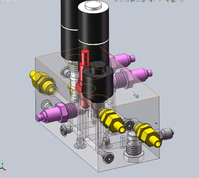
Valve blocks integrate multiple fluid channels, ports, and valve interfaces into a single compact component. They are used in hydraulic power units, mobile machinery, industrial automation, and process control.
The main functions include:
- Distributing and directing pressurized fluid between pumps, valves, and actuators
- Reducing leak paths by replacing multiple fittings and hoses with internal passages
- Providing mounting and interface surfaces for cartridge valves, directional valves, pressure controls, and sensors
- Withstanding static and dynamic pressures while maintaining dimensional stability
To fulfill these roles, valve blocks require correct material selection, accurate machining of internal passages, and reliable sealing surfaces.
Common Materials for Valve Block Machining
Material selection affects machinability, weight, corrosion resistance, pressure capability, and total cost. The choice is typically driven by working pressure, fluid type, environment, and production volume.
Carbon Steel Valve Blocks
Carbon steels are widely used for medium- to high-pressure hydraulic manifolds due to their strength and cost-effectiveness.
Typical grades include:
- Low carbon: C20 / 1.0402, AISI 1020, S235
- Medium carbon: C45 / 1.0503, AISI 1045
- Engineering steels: 42CrMo4 / 1.7225, AISI 4140
Key characteristics:
Advantages: good strength, wide availability, suitable for high-pressure blocks (often up to 350 bar and beyond), relatively low material cost.
Limitations: requires surface protection (zinc plating, phosphating, painting, or nickel plating) against corrosion; machining of higher-strength grades may require optimized cutting tools and coolant; heavier than aluminum.
Alloy and High-Strength Steels
For very high-pressure systems or safety-critical applications, alloy steels with higher yield strength are used. Typical grades:
- 42CrMo4 QT (quenched and tempered)
- AISI 4340 and similar high-strength alloys
These materials allow smaller blocks for the same pressure rating but require robust cutting tools, stable fixtures, and controlled heat treatment. They are common in heavy industrial, mining, and high-pressure test equipment.
Aluminum Valve Blocks
Aluminum is prevalent in mobile hydraulics and pneumatics where weight reduction and good machinability are important.
Typical grades:
- 6000 series: 6061-T6, 6082-T6 (general-purpose manifolds)
- 7000 series: 7075-T6 (higher strength, more demanding service)
Characteristics:
Advantages: significantly lighter than steel, excellent machinability (high cutting speeds, good surface finish), good corrosion resistance, reduced cycle time and tooling wear.
Limitations: lower allowable working pressure than steel for a given size, more susceptible to damage from over-tightening fittings, thermal expansion must be considered for precision assemblies.
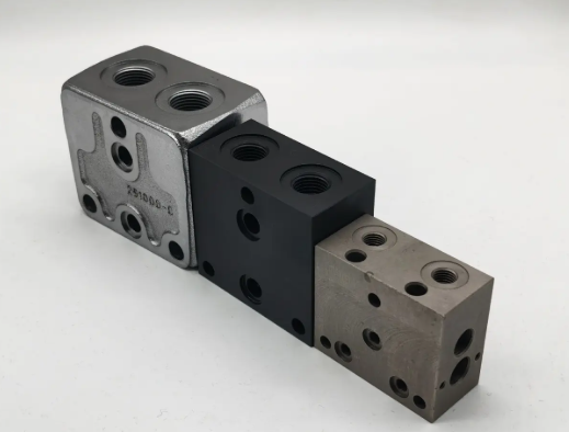
Stainless Steel Valve Blocks
Stainless steels are used where corrosion resistance is critical: marine, offshore, chemical processing, food and beverage, and aggressive fluids.
Typical grades:
- AISI 316 / 316L for excellent corrosion resistance
- AISI 304 for less demanding environments
Key points:
Advantages: high corrosion resistance, suitable for saline or chemically aggressive media, compatible with a wide range of fluids.
Limitations: higher material cost, lower thermal conductivity (heat buildup in machining), potential work-hardening behavior requiring controlled cutting parameters and tool selection.
Special Materials and Considerations
In specialized situations, other materials may be used:
- Brass: good machinability, adequate corrosion resistance for certain fluids, common in pneumatics and low-pressure hydraulics.
- Ductile iron: used for certain valve bodies and blocks with favorable strength and castability.
- Nickel alloys and duplex stainless steels: used in extreme corrosion or high-temperature environments, with significantly higher material and machining cost.
Material certificates (e.g., EN 10204 3.1) and traceability are often required for safety-critical industries such as oil and gas.
Design Features Impacting Machining
Valve block design strongly affects machining complexity, cycle time, and cost. Practical design for manufacturing (DFM) can reduce costs without compromising functionality.
Internal Passages and Cross-Drilling
Blocks typically contain multiple intersecting bores for fluid routing. Common features include:
- Straight drilled holes connecting ports and valve cavities
- Cross-drilled channels with plugs to close machining access holes
- Counterbores and chamfers to accommodate seals and fittings
Technical considerations:
Intersection alignment: positional tolerances for intersecting bores are critical to avoid flow restrictions or partial sealing.
Burr control: internal burrs at cross-holes can create contamination or restrict flow and require deburring processes.
Valve Cavities and Port Interfaces
Many hydraulic valve blocks integrate standardized cavities:
- ISO 7368, ISO 7789, ISO 7790 and similar cavity standards
- Cartridge valve cavities according to manufacturer standards
- NG6, NG10, CETOP, and ISO sandwich plate patterns for directional valves
These cavities include precise bores, shoulders, grooves, and sealing surfaces. Flatness, perpendicularity, and surface roughness directly influence leakage rate and component lifetime.
Mounting, Handling, and Weight-Reduction Features
Designs may include:
- Mounting holes, threaded inserts, and alignment dowel holes
- Lift points and chamfers for safe handling and assembly
- Pocketing or lightening cuts in large blocks to reduce weight while maintaining strength
Machining of these features must maintain structural integrity and avoid creating stress concentrations that could initiate cracks under cyclic loading.
Machining Methods for Valve Blocks
Valve blocks are usually produced from solid bar or plate material using a combination of drilling, milling, turning, and finishing operations. The specific process plan depends on batch size, complexity, and required precision.
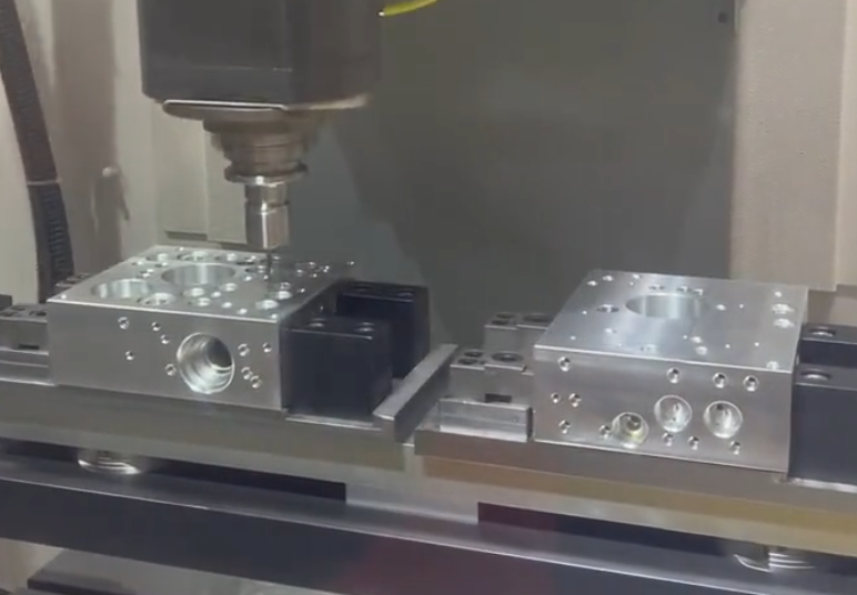
CNC Milling and Drilling
CNC machining centers are the primary equipment for valve block production. Key process steps:
- Rough milling to create the external block shape and reference surfaces
- Drilling of through-holes and blind holes
- Counterboring, reaming, and boring for precision diameters
- Face milling of sealing surfaces and valve mounting pads
- Thread tapping (through holes and blind holes)
Four-axis or five-axis CNC machining centers are often used to reduce setups for multi-side machining. Rotary tables or trunnion fixtures allow access to multiple faces in a single clamping, improving accuracy and reducing cycle time.
Turning Operations
Standard valve blocks are usually prismatic, but some valve bodies are cylindrical or include turned features such as:
- Round manifolds or sub-assemblies
- Valve sleeves and insertable cavities
- Spigots, collars, and pilot diameters for precise alignment
These features are produced on conventional or CNC lathes with boring, grooving, and threading operations as required.
Gun Drilling and Deep Hole Drilling
Deep internal channels can be machined using conventional long drills or dedicated gun drilling machines. Gun drilling is used when:
- Length-to-diameter ratio is high (e.g., > 10:1–20:1)
- High straightness and low runout are required
- Coolant through the tool is required for chip evacuation
Key parameters include spindle speed, feed rate, coolant pressure, and guide bushings to maintain accuracy.
Reaming and Boring for Precision Diameters
Valve cavities and critical bores often require tight tolerances and good roundness. Typical operations:
- Drilling to undersize followed by reaming to final diameter
- Boring with single-point tools for higher precision and alignment
Typical tolerance ranges for critical bores may lie between IT7 and IT9, with surface roughness values often between Ra 0.4–1.6 μm, depending on function and sealing method.
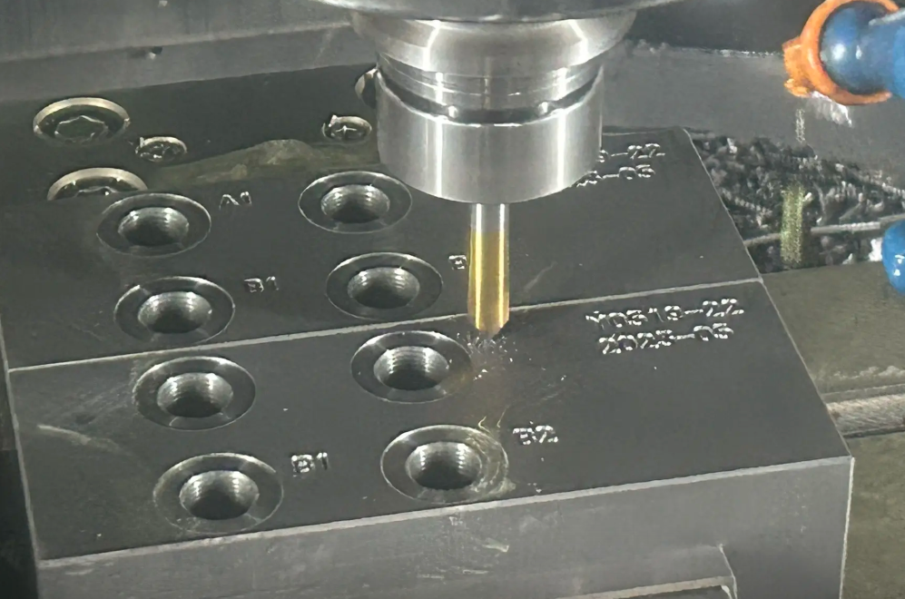
Threading Operations
Valve blocks include multiple threaded ports and connections:
- Metric threads (e.g., M8, M10, M12)
- BSPP/BSPT, NPT, and SAE threads for hydraulic fittings
- UN/UNF threads for cartridge valves and instrumentation
Threads can be produced by tapping (rigid tapping on CNC), thread milling, or thread turning (for larger diameters). Accurate thread depth, concentricity, and chamfering are essential for leak-tight connections.
Deburring and Edge Finishing
Internal burrs and sharp edges are a typical pain point in valve block machining. Unremoved burrs can:
- Contaminate hydraulic systems and damage valves
- Restrict flow at cross-holes
- Interfere with sealing surfaces
Deburring methods include:
- Manual deburring with tools and abrasive stones
- Brush deburring in the machine tool
- Thermal deburring (explosive gas mixture burns off internal burrs)
- Electrochemical deburring for specific geometries
Process selection depends on the complexity of internal passages and the required cleanliness level.

Surface Finish and Tolerances
Surface finish and dimensional tolerances determine leakage behavior, assembly fit, and fatigue performance of valve blocks.
Surface Roughness Requirements
Typical requirements for hydraulic valve blocks include:
- Sealing surfaces: Ra 0.4–0.8 μm
- Valve mounting faces: Ra 0.8–1.6 μm
- Non-critical external faces: Ra 3.2 μm or coarser
- Internal flow passages: Ra 1.6–3.2 μm depending on application
Roughness is controlled via tooling selection, cutting parameters, and toolpath strategies. Surface finish measurement is performed using contact profilometers or other suitable instruments.
Dimensional and Geometric Tolerances
Example tolerance classes:
- Diameters for valve cavities: IT7–IT8
- Port positions: positional tolerance typically 0.05–0.2 mm depending on block size
- Parallelism and perpendicularity between faces: 0.02–0.1 mm
- Flatness for sealing faces: 0.02–0.05 mm over typical pad areas
Geometric tolerancing (GD&T) is widely used to define functional relationships between features. Machining fixtures and process sequences are designed to keep critical features referenced to stable datums.
Fit with Seals and Valves
Valve cavities often include O-ring grooves or cone seats. Groove dimensions, surface finish, and corner radii must match the sealing element specification. Undersize or oversize grooves can lead to extrusion, damage, or insufficient compression of the seal.
Cartridge valve manufacturers typically specify cavity dimensions, tolerances, and surface finish requirements. Compliance is important to maintain warranty and avoid functional issues.
Inspection and Quality Control
Valve blocks operate under pressure and often in safety-critical systems. Robust inspection methods are necessary to ensure safety and reliability.
Dimensional Inspection
Dimensional inspection methods include:
- CMM (coordinate measuring machine) for complex 3D geometries and position tolerances
- Height gauges, micrometers, bore gauges, and plug gauges for diameters and depths
- Thread gauges for internal and external threads
Sampling strategies range from 100% inspection for critical features to statistical sampling for non-critical dimensions, depending on production volume and risk assessment.
Pressure and Leak Testing
Pressure testing verifies that internal passages and sealing surfaces can withstand the design pressure. Typical tests include:
- Hydrostatic pressure test: the block is pressurized with water or oil, often to 1.5 times the working pressure, to check for permanent deformation or leakage.
- Air leak test: low or medium pressure air is used with pressure hold or flow measurement to detect leaks at ports and plugs.
Test parameters such as pressure level, holding time, and acceptable leakage values are usually defined by customer or industry standards.
Cleanliness and Contamination Control
Hydraulic systems are sensitive to particulate contamination. Cleanliness requirements for valve blocks may be specified according to ISO 4406 or similar standards.
Measures include:
- Thorough cleaning after machining and deburring (e.g., ultrasonic cleaning, high-pressure washing)
- Clean assembly areas for plugs and fittings
- Protective caps or plugs on ports after final inspection
Cost Drivers in Valve Block Machining
Calculate the Cost of Valve Block Machining
Total cost of valve block production is determined by material, machining time, tooling, setup, inspection, and finishing. Understanding these drivers helps in design and sourcing decisions.
Material Cost Factors
Material cost depends on:
- Material grade (carbon steel vs stainless steel vs aluminum)
- Stock form (bar, plate, forging, or near-net shape)
- Block size and yield (material removed vs finished weight)
Example: a compact aluminum block may have higher raw material price per kilogram than carbon steel, but the lower density and faster machining can reduce total cost per part.
Machining Time and Complexity
Machining time is a primary contributor to cost. Influencing factors:
- Number of operations and tool changes
- Quantity and length of drilled holes
- Number of valve cavities and port patterns
- Requirement for deep hole drilling or multi-axis machining
- Need for manual deburring or internal finishing
Higher complexity generally increases programming time, setup time, and cycle time, which all translate into higher piece price.
Setup, Fixturing, and Batch Size
Setup includes programming the CNC machine, preparing fixtures, and running first-off inspections. Fixturing must ensure rigidity and repeatability while allowing full access to the required faces.
Key points:
- Small batches: setup and programming costs are spread over few pieces, raising unit cost.
- Large batches: economies of scale, but require stable design and demand.
- Dedicated fixtures: higher upfront cost but reduced cycle time for repeat orders.
Tooling and Tool Wear
Cutting tools include drills, end mills, reamers, boring tools, and taps. Tool cost is influenced by:
- Material: stainless steel and high-strength alloys increase tool wear
- Production volume: high-volume series may justify specialized or high-performance tooling
- Required surface finish and tolerances: may require additional finishing tools or optimized geometry
Tool life, tool change time, and tool monitoring impact both direct and indirect costs.
Inspection and Testing Cost
Inspection and testing add time and resource usage. For safety-critical or high-pressure valve blocks, extensive testing is often mandatory:
- Dimensional inspection of all critical features
- Leak and pressure testing for 100% of parts
- Detailed documentation and traceability
These activities require skilled staff, test benches, and calibration systems, which contribute to part cost.
Finishing, Coating, and Marking
Post-machining steps may include:
- Shot blasting or glass bead blasting
- Zinc plating, phosphating, painting, or anodizing (for aluminum)
- Engraving or stamping of port markings, part numbers, flow direction, and safety information
These operations require additional process time and sometimes external suppliers, which adds to delivery time and total cost.
| Parameter | Impact on Cost | Notes |
|---|---|---|
| Material type | Low to high | Carbon steel < aluminum < stainless steel < special alloys |
| Block size and weight | Moderate to high | Larger blocks require more material and longer machining time |
| Number of ports and cavities | High | Each additional port or cavity adds toolpaths and inspection points |
| Internal passage complexity | High | Multiple cross-holes and deep drilling significantly increase cycle time |
| Required tolerances and finish | Moderate to high | Tight tolerances and fine finishes require additional operations and inspection |
| Batch size | Low to high | Small batches have high unit costs due to setup; large batches enable economies of scale |
| Testing and certification | Moderate to high | Pressure testing and certification add labor and equipment time |
| Coating and surface treatment | Low to moderate | External processing can add both cost and lead time |
Process Planning for Valve Block Machining
Effective process planning coordinates material selection, machining steps, and inspection requirements to achieve the required quality at an acceptable cost.
From Design to CNC Program
Typical steps:
- Analyze 3D model and drawing: identify critical features, datums, tolerances, and sealing surfaces.
- Select material and stock size: ensure sufficient machining allowance while minimizing excess material.
- Determine machining strategy: sequence operations to maintain datums and minimize re-clamping.
- CAM programming: generate toolpaths for milling, drilling, reaming, pocketing, and threading.
- Simulation: verify toolpaths for collisions, reachability, and cycle time estimation.
Fixture Design and Workholding
Stable workholding is essential for accuracy and productivity. Typical approaches:
- Vise or clamping blocks for small series and prototypes
- Dedicated fixtures or tombstones for high-volume production
- Zero-point clamping systems to reduce setup time
Fixtures must consider chip evacuation, access to all relevant faces, and repeatability between batches.
In-Process Control
In-process inspection ensures that deviations are detected early. Methods include:
- On-machine probing for reference surfaces and key dimensions
- First-article inspection reports for each new batch or design
- Tool life monitoring to prevent dimension drift caused by wear
Pain Points and Practical Considerations
Some recurring difficulties in valve block machining include:
- Internal burr removal: complex networks of cross-drilled passages can be difficult to deburr completely, requiring supplementary processes like thermal or electrochemical deburring.
- Maintaining flatness on large blocks: uneven material removal or clamping can cause distortion, impacting sealing performance.
- Tool access in dense designs: tightly packed ports and cavities can limit tool access, resulting in additional setups or specialized tools.
- Managing heat and distortion in stainless steel: higher cutting forces and heat generation can affect dimensional stability and tool life.
Summary
Valve block machining combines material science, precision machining, and rigorous quality control. Material choice (steel, aluminum, stainless, or special alloys) must align with pressure, environment, and cost targets. CNC milling, drilling, deep hole drilling, boring, and threading operations generate the complex internal and external geometry, while deburring, surface finishing, and inspection secure functional reliability.
Cost is driven by material type, block size, internal complexity, tolerances, testing requirements, and batch size. Well-planned designs that respect manufacturing constraints can reduce machining time, improve consistency, and lower overall cost while maintaining high performance in demanding hydraulic and pneumatic applications.
FAQ
What is valve block machining?
Valve block machining is the precision manufacturing process of producing hydraulic or pneumatic valve blocks, including drilling, milling, tapping, and finishing internal flow passages and mounting surfaces.
What materials are commonly used in valve block machining?
Valve blocks are typically machined from aluminum alloys, carbon steel, stainless steel, or cast iron, depending on pressure ratings and application requirements.
How are internal burrs removed from valve blocks?
Internal burrs are removed using a combination of manual and automated methods. Manual deburring with tools and brushes is common for accessible intersections. For complex internal passages, thermal deburring or electrochemical deburring is often used to remove burrs in areas that mechanical tools cannot reach. Brush deburring inside the CNC machine can also reduce manual effort.
What is the main cost driver when machining valve blocks?
The primary cost driver is machining time, which is strongly influenced by the complexity of internal passages, number of ports and cavities, and required tolerances. Material type, setup time, tool wear, and testing also contribute to cost, but long drilling cycles, deburring of intersections, and tight tolerance features typically account for a large share of the machining cost per part.
