
A valve block (also called valve manifold, manifold block or integrated valve block) is a compact assembly that combines multiple valves and flow paths into a single body. It is widely used in hydraulic and pneumatic systems to minimize piping, reduce leakage points, simplify installation and centralize control. This guide explains core concepts, design parameters, selection methods and application practices for valve blocks.
Basic Functions and Working Principles
A valve block provides internal channels that connect pumps, actuators, measuring points and control elements through machined passages instead of separate hoses or tubes. Individual valves, plugs and accessories are mounted on or inside the block to form a complete control node.
Typical functions include:
- Distribution of pressure and flow from a common supply to multiple consumers
- Switching and directional control of actuators (cylinders, motors)
- Pressure limitation, pressure reduction and pressure sequence control
- Flow regulation and speed control of actuators
- Isolation, venting, measuring and safety functions
Flow is guided by internal bores and cross-drillings. When a valve is actuated, it opens or closes specific channels, changing how ports on the block are interconnected. The block body itself has no moving parts; functionality is defined by the installed valves and how the internal channels are laid out.
Valve Block Types and Configurations
Valve blocks can be categorized according to medium, structure and mounting concept. Understanding these types helps to match the block to the target application.
Hydraulic vs Pneumatic Valve Blocks
Hydraulic valve blocks handle incompressible fluids such as mineral oil or synthetic hydraulic fluids. They are designed for high pressure, typically up to several hundred bar, with tight tolerances to reduce internal leakage. Common uses include mobile machinery, industrial presses, injection molding machines and hydraulic power units.
Pneumatic valve blocks, often called valve manifolds or valve islands, carry compressed air at lower pressures (commonly 4–10 bar). They prioritize fast response, low weight and ease of replacement. They are widely used in factory automation, material handling and packaging equipment.
Monoblock vs Modular Block Systems
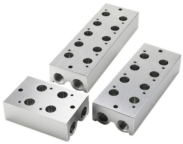
Monoblock valve blocks are machined from a single piece of metal with integrated channels. They offer compactness, high rigidity and few potential leakage points. The internal layout is fixed, which makes later functional changes more difficult.
Modular valve block systems consist of standardized plates or slices that can be combined to build custom circuits. Typical concepts include:
- Sandwich plate valves stacked on a subplate
- Bar manifolds with multiple valve stations along a common passage
- Plate-and-cover systems for cartridge valves
Modularity allows flexible expansion, easier maintenance and customization with standard components.
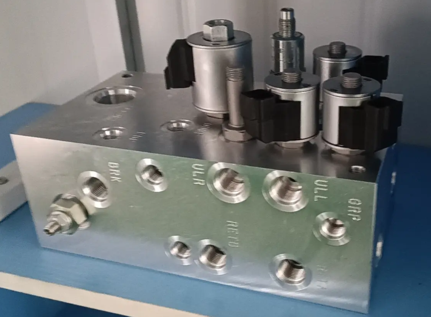
Integrated Hydraulic Manifolds
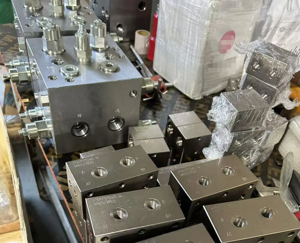
Integrated manifolds combine most hydraulic control functions for a machine axis or an entire system in one block. Screw-in cartridge valves, directional valves, pressure control valves and auxiliary functions are installed into a common body. This approach reduces external piping and is common in compact power packs, mobile equipment and high-performance industrial systems.
Key Design Parameters
Valve block design must satisfy hydraulic or pneumatic performance while ensuring structural integrity, reliability and serviceability. Important parameters include porting, flow capacity, pressure rating, material, sealing and layout.
Port Types, Sizes and Coding
Ports provide the external connection interface for pipes, hoses or actuator ports. Standardized threads and flanges are used to ensure compatibility. E.g., in hydraulics, common thread standards include:
- BSPP (G) threads
- Metric threads with sealing rings
- UN/UNF threads, SAE straight threads
In pneumatics, often BSPP or NPT threads are used for air lines. Each port usually has a code (P = pressure supply, T = tank/return, A/B = actuator ports, L = drain, X/Y = pilot, etc.). Clear marking on the block and documentation is important to avoid misconnections.
Flow Capacity and Pressure Rating
The internal bores and cross-sections of a valve block must handle the required flow without excessive pressure drop. Flow capacity depends on bore diameter, length, roughness and the number and geometry of cross passages.
Pressure rating defines the maximum continuous working pressure and test pressure of the block. Safety factors are applied based on material strength, wall thickness and fatigue requirements. For hydraulic blocks, design pressures can range from 50 bar to 420 bar or more, depending on the application and standard used.
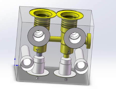
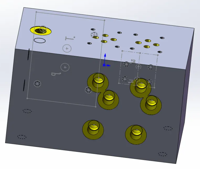
Channel Layout and Internal Cross-Drilling
Internal layout determines how compact and efficient the block will be. Designers define the position and orientation of each valve cavity, then route channels to interconnect them. Important considerations are:
- Minimizing flow paths and sharp turns to reduce pressure drop
- Avoiding intersecting drillings that weaken the structure excessively
- Ensuring complete machining and cleaning access for all channels
- Providing sufficient wall thickness between neighboring drillings
Valve Cavity Standards
Many hydraulic valve blocks use standardized cavities for screw-in cartridge valves (for example, ISO or manufacturer-specific cartridge cavities) or standardized mounting interfaces for directional valves (for example, ISO 4401). Pneumatic manifolds often adopt proprietary bases for plug-in valves, with standardized port sizes.
Standardized cavities and interfaces ensure that different valve types (pressure relief, check, flow control) can be installed into the same block and replaced when necessary.
Materials and Surface Treatments
The material of a valve block influences pressure capability, machinability, corrosion resistance and weight. Surface treatment further improves corrosion resistance and cleanliness.
| Material | Typical Use | Advantages | Considerations |
|---|---|---|---|
| Carbon steel (e.g., C45) | High-pressure hydraulic manifolds | High strength, good machinability | Requires surface protection against corrosion |
| Alloy steel | Very high pressure or fatigue-critical systems | Higher strength and fatigue resistance | Higher cost, heat treatment may be needed |
| Stainless steel | Corrosive environments, offshore, process industry | Excellent corrosion resistance | Higher material and machining cost |
| Aluminum | Pneumatics, low to medium pressure hydraulics | Low weight, good machinability | Lower maximum pressure, needs suitable fluid compatibility |
| Brass | Instrumentation, low pressure, small manifolds | Good corrosion resistance, easy machining | Limited pressure capability, material cost |
Common surface treatments include zinc plating, phosphating, anodizing (for aluminum), nickel plating and painting. Choice depends on environment, cleanliness requirements and aesthetic or identification needs.
Common Valve Functions in a Block
A valve block combines several valve types to achieve the desired circuit behavior. Typical valve functions integrated into a block are described below.
Directional Control Valves
Directional valves determine the path of flow between pump, tank and actuator ports. In hydraulic valve blocks they can be spool-type valves mounted on an interface or screw-in cartridges. In pneumatic manifolds they are typically solenoid valves controlling air to cylinders or grippers.
Key parameters include number of ports (e.g., 4/3, 4/2, 5/2, 5/3), switching position, actuation type (solenoid, hydraulic pilot, mechanical) and flow capacity.
Pressure Control Valves
Pressure relief valves, pressure reducing valves, sequence valves and unloading valves maintain system pressure within defined limits and coordinate actuators. They are often located near the pressure inlet and along critical branches. Proper selection and positioning helps prevent overloads and ensures stable operation.
Flow and Check Valves
Flow control valves regulate the speed of cylinders and motors by limiting flow rate. Check valves allow flow in one direction and block it in the opposite direction, often combined with flow control (one-way flow control).
Integrating these valves into the block reduces external piping and allows for more accurate and stable control, especially with short distances between valve and actuator port.
Shut-Off, Measuring and Safety Functions
Blocks can incorporate shut-off valves for isolation, test points for pressure measurement, filters or screens at inlets, and safety elements such as counterbalance valves for load holding. Integrating safety and measuring functions in the block simplifies commissioning and service and reduces the number of external components.
Hydraulic Valve Block Design Considerations
Designing a hydraulic valve block requires systematic assessment of mechanical, hydraulic and maintenance-related aspects. Proper engineering prevents internal leakage, pressure drop issues and structural failures.
Strength Calculation and Wall Thickness
The block must withstand internal pressure without cracking or excessive deformation. Minimum wall thickness between internal channels and between channels and outer surfaces is defined based on pressure, material and applicable standards or company rules.
Finite element analysis is often used to identify critical areas around cross-drillings, cavities and mounting holes. The designer must avoid too many intersections in a small area and ensure sufficient support around threaded ports and large cavities.
Heat, Viscosity and Contamination Aspects
In hydraulic systems, flow through restrictions generates heat. Block layout influences where throttling occurs and how heat is distributed. Excessive temperature affects fluid viscosity and, consequently, internal leakage and response behavior. Designers consider expected temperature range and fluid type when defining clearances, seals and tolerances.
Contaminants can accumulate in dead zones or pockets. Internal shapes should promote self-draining and flow-through where appropriate. Filtration and cleanliness levels must match valve sensitivity.
Mounting Interfaces and Sealing
Hydraulic blocks use O-rings, profile seals or metal-to-metal sealing between block and valves or cover plates. Groove design, surface finish and compression are critical for sealing reliability. Mounting interfaces follow standards such as ISO 4401 or manufacturer-specific cartridge landing dimensions.
Bolt selection and tightening torque must ensure uniform compression without deforming the block. Thread engagement length is defined to prevent stripping at maximum clamping forces.
Pneumatic Valve Manifolds and Islands
Pneumatic valve blocks are tailored for fast, modular, electrically controlled distribution of compressed air. They focus on ease of electrical connection, compactness and simple channel routing.
Valve Island Architecture
A typical valve island consists of a base manifold with multiple stations, onto which individual solenoid valves are plugged. Common air supply channels run longitudinally through the manifold, while outlet ports for actuators are arranged along the side or top. Electrical interfaces can be discrete wiring terminals or fieldbus/industrial Ethernet modules.
Flow, Pressure and Response Time
Pneumatic manifolds are designed for relatively low pressures but high switching frequencies. Flow capacity is often specified as nominal flow at a defined pressure drop, or by using coefficients such as Cv. Designers must ensure that the manifold cross-sections are adequate to supply all valves operating simultaneously without unacceptable pressure drop or delay.
Valve response time and internal volume of channels directly affect actuator speed. Short and appropriately sized passages from valve outlet to actuator port minimize delay and improve repeatability.
Electrical Interfaces and Diagnostics
Many modern pneumatic valve blocks integrate electrical connectors, LED status indicators and diagnostic capabilities. The manifold may support multi-pin connectors, fieldbus nodes or IO-link interfaces. Diagnostic features can include coil status, short-circuit detection, open-circuit detection and channel-level monitoring. Although these functions are mainly linked to the valve and electronics, the mechanical manifold layout must provide space and thermal management for them.
Mounting, Installation and Integration
Correct installation of valve blocks affects performance and service life. Consideration of mounting position, accessibility, vibration and environmental exposure is essential.
Mounting Methods and Orientation
Valve blocks may be mounted on machine frames, inside control cabinets or on mobile vehicle structures. Typical methods include:
- Through-bolting holes in the block to a base plate or bracket
- Use of mounting feet or rails
- Flange mounting between piping sections
Orientation may affect air bleeding, drainage and contamination accumulation. Hydraulic blocks for high pressure often include dedicated venting and bleed ports at high points. Designers should consider service access to valves, connectors, plugs and measuring points.
Connection to Piping and Hoses
Choice of connection technology (threaded connectors, flanges, quick couplers) influences leakage risk and maintenance ease. The block should be located to minimize hose lengths to actuators while avoiding sharp bends and mechanical stress at ports.
For manifolds supplying multiple consumers, balanced routing and support of attached piping help reduce vibration and fatigue.
Integration into Control Systems
In hydraulic systems, valve blocks may be controlled by hydraulic pilot lines from a primary valve or by proportional solenoid valves driven by an electronic controller. In pneumatic systems, valve islands are typically integrated via fieldbus into PLC-based automation systems.
Proper documentation of port designations, signal mapping and function charts is important for commissioning and troubleshooting. The block should be labeled with identifiers matching the schematic diagram.
Typical Applications of Valve Blocks
Valve blocks are used wherever multiple flow paths must be controlled from a compact, centralized location. Typical application areas include:
Industrial Machinery
In industrial hydraulics, valve blocks control presses, injection molding machines, machine tools, lifting devices and test benches. Integrated manifolds provide pressure control, motion sequences, clamping and safety functions. In pneumatics, manifolds distribute air to handling systems, conveyors and robotic end effectors.
Mobile and Off-Highway Equipment
Construction machinery, agricultural equipment, cranes and utility vehicles often rely on integrated hydraulic manifolds or monoblock valves. These blocks combine loader, steering, stabilizer and auxiliary functions. Compact design and high resistance to vibration and contamination are important requirements in these environments.
Process and Instrumentation Systems
In process industries, small manifold blocks combine isolation valves, bleed valves and test ports for instruments such as pressure transmitters and flow meters. They enable safe isolation and calibration without disturbing the main process lines. Stainless steel and high corrosion resistance are typical demands.
Selection Criteria for Valve Blocks
Selecting or specifying a valve block requires matching its functional, mechanical and operational characteristics to the system requirements. A structured approach reduces the risk of oversizing, undersizing or incompatibility.
Functional and Circuit Requirements
The starting point is a clear hydraulic or pneumatic circuit diagram defining all functions: number and type of actuators, required motions, load levels, control logic and safety features. From this, the designer determines how many valve stations are required, which valve functions are needed and which ports must be accessible from outside the block.
Capacity, Pressure and Medium
Flow rate, working pressure and fluid or gas type determine the size and rating of the block. Designers check:
- Maximum and typical flow at supply and actuator ports
- Maximum working pressure and potential pressure peaks
- Fluid viscosity, temperature range and compatibility with block material and seals
These conditions must remain within the published specifications of the block and installed valves to ensure safe operation.
Environmental and Maintenance Requirements
Ambient temperature, humidity, exposure to chemicals or salt water, vibration and shock all affect material and mounting choices. Corrosion protection and robust mechanical interfaces may be necessary. Maintenance strategy (on-site repair vs exchange, planned downtime intervals) influences whether a modular or monoblock concept is preferable.
Common Issues and Design Considerations
While valve blocks reduce external piping and potential leakage points, improper design or selection can lead to specific issues. Understanding these considerations helps to achieve reliable operation.
Internal Leakage and Pressure Drop
Excessive pressure drop can cause energy loss, heating and insufficient actuator speed. It is influenced by undersized passages, abrupt direction changes and restrictive components. Internal leakage due to machining tolerances or wear affects efficiency and positioning accuracy. Designers balance compactness with adequate passage size to minimize these effects.
Contamination Sensitivity
Integrated blocks concentrate multiple valve functions in one body. Contamination entering the block can impact several functions simultaneously. Good filtration, cleanliness during assembly and appropriate material and surface choices are essential. Some designs include integrated filters or screens at critical inlets.
Service and Modification Constraints
Monoblock designs are compact but less flexible if later changes to the circuit are required. Once channels are drilled, functional changes may require a new block. Modular systems offer better adaptability but may be larger. Service access to individual valves, plugs and measuring points must be considered at design stage so that routine maintenance can be performed without extensive dismantling.
Manufacturing and Quality Control
Valve block performance depends heavily on manufacturing quality. Machining, cleaning and testing are key steps in production.
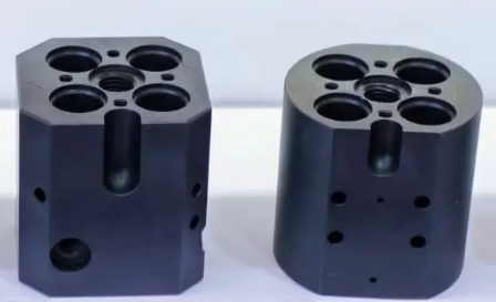
Machining, Deburring and Cleaning
Blocks are manufactured by drilling, milling, boring and tapping operations. Deburring of cross-drillings and transitions is essential to prevent loose burrs that may damage valves or block channels. Internal surfaces must be free of chips, cutting fluids and contamination.
Cleaning processes can include flushing, ultrasonic cleaning and high-pressure washing. Cleanliness requirements are defined based on the sensitivity of valves and the system cleanliness class.
Pressure Testing and Documentation
Each valve block is typically pressure tested to verify strength and sealing. Test pressure is higher than maximum working pressure according to internal or external standards. Leak testing may be performed using hydraulic fluid, air or inert gas.
Documentation covers materials, test records, port identification and, in some cases, unique serial numbers. For custom manifolds, detailed assembly drawings and circuit descriptions are supplied to the user.
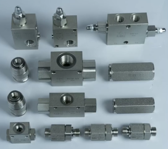
Comparison of Valve Block Concepts
Different valve block concepts offer varying advantages regarding compactness, flexibility and cost. Comparing them helps in choosing the appropriate architecture for a project.
| Concept | Typical Medium | Main Characteristics | Typical Use Cases |
|---|---|---|---|
| Monoblock hydraulic manifold | Hydraulic oil | Very compact, fixed internal layout, few leakage points | Mobile equipment, compact power units, dedicated machine axes |
| Modular sandwich plate manifold | Hydraulic oil | Stackable functions, standardized interfaces, flexible configuration | Industrial machinery with variable functions, easily expandable systems |
| Cartridge valve manifold | Hydraulic oil | High integration using screw-in valves, custom internal routing | High-performance and customized hydraulic systems |
| Pneumatic valve manifold / island | Compressed air | Plug-in valves, integrated electrical interface, low pressure | Factory automation, conveying, handling and packaging |
| Instrumentation valve manifold | Process fluids and gases | Isolation, venting and calibration combined in compact blocks | Process measurement lines, pressure and differential pressure transmitters |
FAQ about Valve Blocks
What is a valve block?
A valve block is an integrated hydraulic or pneumatic component that combines multiple valves and flow passages into a single compact unit. It helps control fluid direction, pressure, and flow efficiently.
What are valve blocks used for?
Valve blocks are commonly used in hydraulic systems for industrial machinery, construction equipment, agricultural machines, and automation systems to simplify piping and improve system reliability.
What types of valves can be integrated into a valve block?
Commonly integrated valves include directional control valves, pressure relief valves, check valves, flow control valves, and proportional valves.
How do I choose the right valve block for my system?
Selection depends on system pressure, flow rate, fluid type, operating temperature, and required functions. Consulting technical drawings or a hydraulic engineer is recommended.
What are the advantages of using a valve block?
Valve blocks reduce leakage points, save installation space, improve system response, and make maintenance easier compared to traditional piping systems.
