
Turbocharger impellers are critical rotating components that convert exhaust gas or shaft power into compressed intake air. Their design, material selection, and manufacturing route directly determine turbocharger efficiency, durability, and allowable operating range. This article presents a systematic overview of impeller functions, design features, material options, manufacturing processes, inspection requirements, and typical engineering data for automotive and industrial turbochargers.
Core Functions of a Turbocharger Impeller
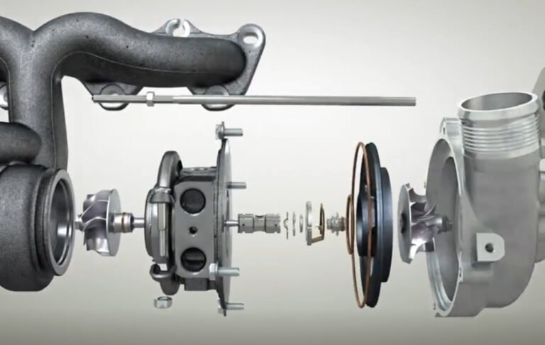
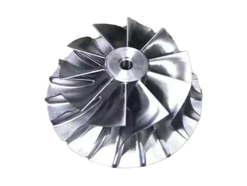
The term “turbocharger impeller” is often used mainly for the compressor wheel, but in many engineering contexts it also broadly covers the turbine wheel. Both components are wheel-shaped rotors with aerodynamically profiled blades mounted on a common shaft. They perform different but tightly coupled functions.
Compressor Impeller Function
The compressor impeller (compressor wheel) draws ambient air into the turbocharger and increases its total pressure and velocity. It typically operates as a centrifugal or mixed‑flow stage.
- Accelerates intake air radially (centrifugal compressor) or diagonally (mixed-flow compressor)
- Generates static pressure rise when air exits the impeller into the diffuser and volute
- Determines achievable boost pressure ratio and mass flow range
- Influences turbocharger surge margin and choke flow characteristics
Performance of the compressor impeller is expressed in terms of pressure ratio, adiabatic efficiency, and flow capacity at given shaft speeds. Geometry such as inducer diameter, exducer diameter, blade angles, and splitter arrangement strongly affects these metrics.
Turbine Impeller Function
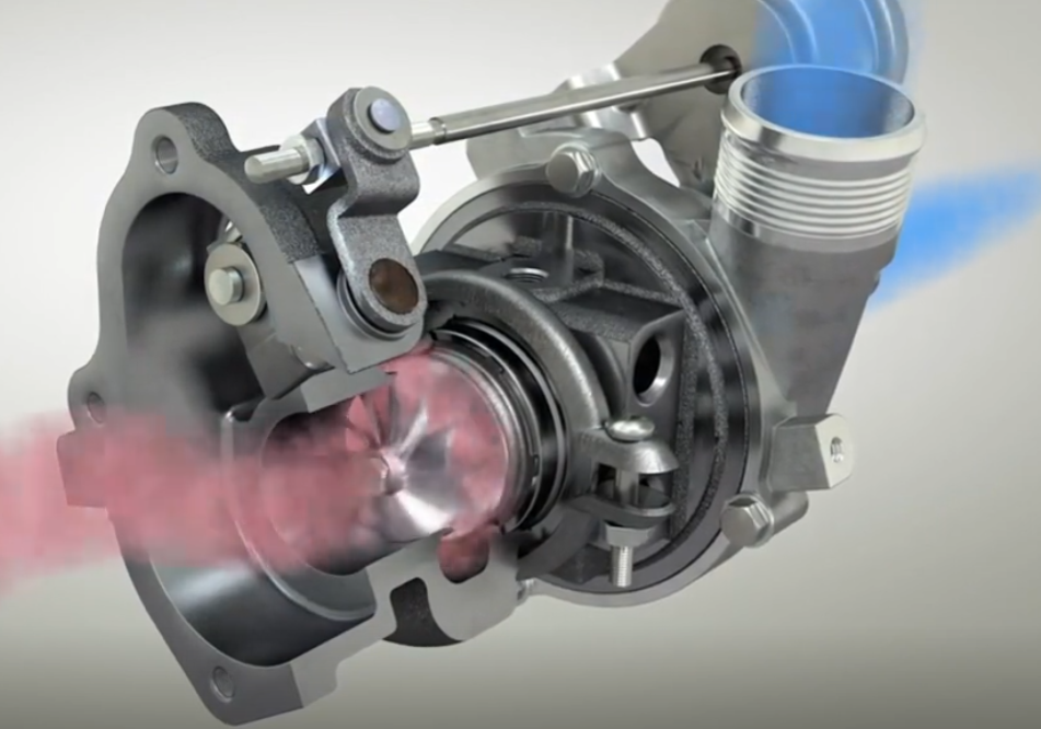
The turbine impeller (turbine wheel) extracts energy from the exhaust gas stream and converts it into shaft power to drive the compressor wheel.
- Receives high-temperature exhaust gas from the turbine housing scroll or volute
- Converts thermal and kinetic energy into mechanical work via blade loading
- Controls turbocharger response, backpressure and overall efficiency
Turbine impeller effectiveness is described by efficiency, flow capacity, swallowing capacity, and matching to the engine’s exhaust pulse characteristics. Turbine wheel material and cooling are crucial because it operates at elevated temperatures, especially in gasoline and high-power diesel applications.
Key Design Features of Turbocharger Impellers
Turbocharger impeller design is highly specialized. Geometric parameters must meet aerodynamic, structural, and manufacturing requirements within a compact envelope. The following features are typical for modern turbocharger impellers.
Geometry of Compressor Impellers
Compressor impellers are usually centrifugal or mixed-flow designs, optimized for high tip speed and compact installation.
Typical geometric elements include:
- Inducer diameter and exducer diameter
- Blade count (main blades plus splitter blades)
- Blade inlet and outlet angles
- Hub and shroud contours
- Backface profile and nose hub shape
- Tip clearance and shroud design
Key dimensional ranges for light‑duty automotive compressors:
| Parameter | Common Range (Passenger Car / Light-Duty) |
|---|---|
| Inducer diameter | 30–60 mm |
| Exducer diameter | 40–80 mm |
| Blade count (full + splitter) | 6–8 full blades + 6–8 splitters |
| Tip speed (max) | 350–550 m/s (dependent on material and design) |
| Rotational speed (max) | 120,000–250,000 rpm |
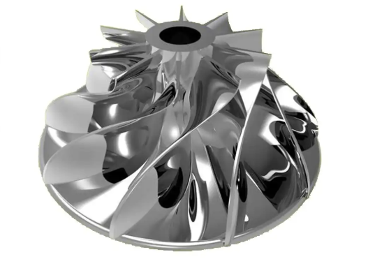
Blade profiles are three‑dimensional, with varying thickness and curvature along the span. Splitter blades are shorter blades inserted between main blades to improve flow guidance and reduce diffusion, enhancing efficiency and extending the operating map.
Geometry of Turbine Impellers
Turbine impellers are usually radial or mixed‑flow wheels. They must balance efficiency, pressure ratio capability, and inertia for fast transient response.
Key geometric aspects:
- Tip diameter and hub diameter
- Blade count and chord length
- Blade throat area and passage area distribution
- Backface and hub profile
- Root fillet radii and stress relief features
Typical turbine wheel ranges for light‑duty vehicles:
| Parameter | Common Range (Passenger Car / Light-Duty) |
|---|---|
| Tip diameter | 35–70 mm |
| Blade count | 9–12 blades |
| Rotor speed (max) | 120,000–250,000 rpm |
| Exhaust gas temperature (typical steady) | 700–1050 °C (application dependent) |
Turbine blades are usually relatively thin with carefully designed leading and trailing edges to reduce losses. Fillet radii at the blade root and hub transition are essential to limit local stress concentrations due to centrifugal and thermal loads.
Backface, Nose and Bore Features
On both compressor and turbine impellers, the backface and nose regions serve structural and mounting functions:
Backface surfaces provide support for the blades and distribute stresses. The thickness and curvature must accommodate centrifugal loading and potential thermal gradients on the turbine side.
The nose region defines the flow entry for compressor impellers and contributes to surge behavior and inlet losses. Smooth, well‑blended contours minimize flow separation at high incidence angles.
The central bore or shaft hole connects the impeller to the common shaft. Bore geometry may include:
- Cylindrical bore with interference fit or shrink‑fit
- Tapered bore for precise centering
- Keyways, splines, or threaded portions, depending on assembly concept
Tolerances on bore diameter, run‑out, and perpendicularity directly affect rotor balance.
Balance and Mass Distribution
Turbocharger impellers must be balanced precisely due to their high rotational speeds. Even small mass asymmetries can generate large unbalance forces that cause vibration, bearing wear, and fatigue.
Design measures include:
- Symmetrical blade distribution and hub geometry
- Machined balance pads or lands on backface or hub
- Controlled material removal in designated areas during balancing
Impellers are typically balanced as part of a rotor sub‑assembly. Residual unbalance limits are defined according to rotor grade standards and the specific turbocharger application.
Material Options for Turbocharger Impellers
Material selection must consider mechanical strength, temperature capability, fatigue resistance, corrosion and oxidation behavior, manufacturability, and cost. Compressor and turbine impellers are usually made of different materials due to the distinct thermal environments on each side.
Compressor Impeller Materials
Compressor impellers operate at relatively moderate temperatures but very high rotational speeds and experience cyclic mechanical loading. Common material categories include:
1) Cast Aluminum Alloys
Cast aluminum alloys are widely used for passenger car and light‑duty compressor wheels because they offer low density, good machinability, and adequate strength at compressor operating temperatures.
Typical characteristics:
- Density: approximately 2.6–2.8 g/cm³
- Ultimate tensile strength: 250–400 MPa (alloy and heat treatment dependent)
- Good castability and fine feature reproduction
- Temperature capability typically up to about 200–250 °C for long-term operation
Alloys are usually heat‑treated (e.g., T6 condition) to achieve sufficient strength and fatigue performance. They may include copper, silicon, magnesium, or zinc to optimize mechanical properties.
2) Forged Aluminum Alloys
Forged aluminum compressor wheels are used when higher strength and fatigue resistance are required. Forging results in a refined grain structure and improved ductility compared to cast alloys.
Benefits include:
- Higher allowable tip speeds for a given safety factor
- Reduced risk of porosity-related defects
- Improved low‑cycle and high‑cycle fatigue performance
Forged blanks are machined into the final impeller geometry, often using 5‑axis CNC machining. Heat treatment is applied before or after forging depending on the alloy and process route.
3) Titanium Alloys
Titanium alloys are used for high-performance compressor impellers that require very high tip speeds combined with low mass and corrosion resistance.
Typical characteristics:
- Density: approximately 4.4–4.6 g/cm³ (higher than aluminum, but lower than steel)
- High specific strength and stiffness
- Good corrosion resistance in intake air environments
- Temperature capability above typical compressor temperature levels
Manufacturing titanium impellers is more complex and costly due to material price, machining difficulty, and the need for controlled forging or milling processes.
4) Steel and Stainless Steel
Some applications use steel or stainless steel compressor wheels, especially in environments with potential for erosion, foreign object damage, or special operating conditions. They offer high strength and good fatigue resistance, but mass and inertia increase compared to aluminum or titanium.
Turbine Impeller Materials
Turbine impellers sit in the hot exhaust gas stream and are subject to high temperatures, thermal gradients, and oxidation. Material selection is dominated by temperature capability, creep resistance, and oxidation resistance while maintaining sufficient strength at elevated temperatures.
1) Inconel and Other Nickel-Based Superalloys
Nickel-based superalloys, often generically referred to as Inconel-type materials, are the standard choice for turbine wheels in many turbochargers.
Key attributes:
- Excellent high-temperature strength and creep resistance
- Good oxidation and corrosion resistance in exhaust environments
- Retention of mechanical properties up to 800–950 °C (alloy dependent)
These alloys are typically investment cast to form complex blade shapes and then heat-treated. Superalloys often include chromium, cobalt, molybdenum, titanium, and aluminum in controlled proportions.
2) Austenitic Heat-Resistant Steels
For moderate-temperature applications, austenitic heat‑resistant steels can be used. They offer lower cost than nickel-based superalloys and acceptable behavior at lower peak exhaust temperatures.
3) Martensitic or Precipitation-Hardening Steels
Certain turbine wheels for specific industrial applications may use martensitic or precipitation-hardening steels, combining relatively high strength with tailored heat treatment. Their temperature capability is generally lower than that of nickel-based superalloys.
4) Material-Property Considerations
Material selection must take into account:
- Yield and ultimate tensile strength at operating temperature
- Fatigue strength under combined thermal and mechanical cycling
- Creep behavior during high-temperature, long-duration operation
- Thermal expansion and compatibility with shaft and housing materials
- Oxidation and hot corrosion resistance with specific fuel and exhaust compositions
In many designs, the turbine wheel material defines the permissible exhaust gas temperature for continuous operation. Safety factors are applied to account for temperature gradients and transient operating conditions.
Manufacturing Processes for Turbocharger Impellers
Manufacturing methods must deliver dimensional accuracy, surface quality, mechanical properties, and consistency at competitive cost. The chosen process depends on the material and volume requirements.
Investment Casting
Investment casting is extensively used for turbine impellers and some compressor impellers. The process allows complex blade shapes, thin sections, and integrated hub geometries.
Typical investment casting steps:
- Wax pattern creation using a precision die
- Assembly of wax patterns into a cluster
- Building of a ceramic shell by dipping and stuccoing
- Wax removal and shell firing
- Metal pouring into the heated ceramic shell
- Shell removal, gate cutting, and initial finishing
Investment casting yields near‑net‑shape components with minimal material waste. Process control is critical to minimize defects such as porosity, inclusions, and misruns. Heat treatment, straightening, and final machining follow casting.
Sand Casting
Sand casting can be used for large turbocharger impellers, typically in industrial and marine applications where sizes are larger and volumes may be lower. Sand molds allow flexible geometry but provide lower surface finish and dimensional accuracy compared to investment casting. Additional machining is required to reach final tolerances and surface specifications.
Forging and Machining
Forging is common for high-strength aluminum or titanium compressor impellers and for some steel components. The forging process compacts the material, reduces porosity, and aligns the grain structure to improve mechanical properties.
Process outline:
- Preparation of alloy billets and heating to forging temperature
- Closed-die forging into a preform or near‑net‑shape blank
- Flash trimming and cooling
- Heat treatment (solution treatment and aging, or other specified sequence)
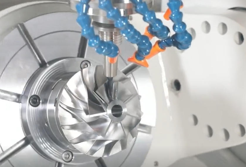
- 5‑axis CNC machining of blades, hub, bore, and backface
The final geometry is achieved by precision machining, allowing tight dimensional control and surface finish. Balance pads and other features can be integrated during machining.
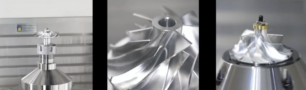
Fully Machined Impellers from Solid Stock
Some compressor wheels, especially prototypes, small series parts, or high-performance titanium designs, are milled entirely from solid bar or plate stock. Modern 5‑axis machining centers can produce complex blade geometries without casting tooling.
Advantages:
- No casting defects such as porosity or inclusions
- Flexible geometry changes without new casting dies
- High dimensional accuracy and surface quality
This approach usually has higher material usage and longer machining time, so it is mainly applied where series volumes are limited or performance requirements justify higher cost.
Additive Manufacturing (Metal AM)
Metal additive manufacturing (for example, powder bed fusion) can be used to produce prototype or special-application impellers. It enables complex internal cooling passages or novel blade geometries. After printing, impellers require heat treatment, surface finishing, and extensive validation. Due to cost and throughput, additive techniques are more common in development or specialized industrial applications than in high-volume production.
Heat Treatment and Surface Finishing
Heat treatment is essential to achieve specified strength, ductility, and fatigue properties.
Typical procedures include:
- Solution treatment and aging for aluminum alloys
- Precipitation hardening for nickel-based superalloys
- Stress-relief annealing after casting or forging
Surface finishing operations may comprise:
- Shot peening of critical areas to introduce compressive residual stresses
- Polishing of blade surfaces to reduce roughness and improve flow
- Deburring of edges and removal of machining marks
Surface engineering improves fatigue performance, corrosion resistance, and aerodynamics. Appropriate control of these steps ensures repeatable performance and endurance.
Precision Machining and Tolerances
Regardless of the forming process, final geometry is defined by precision machining. High‑speed, multi-axis CNC machines are commonly used for both compressor and turbine wheels.
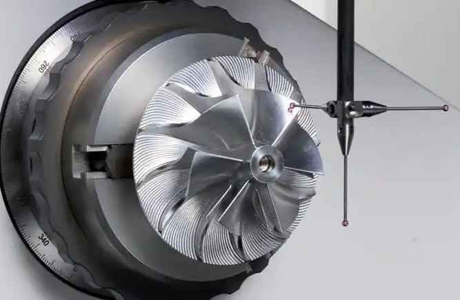
Dimensional Tolerances
Typical tolerance requirements include:
- Blade thickness and chord within tight limits to ensure flow consistency
- Hub and shroud profiles within small form tolerance bands
- Bore diameter and run‑out relative to blade envelopes
- Overall diameter and width tolerances for housing fit
These tolerances are necessary to ensure aerodynamic balance between stages, to control tip clearance, and to avoid mechanical interference with housings and seals.
Balancing Operations
Impellers are usually balanced as part of a rotor assembly that includes the compressor wheel, turbine wheel, and shaft.
Balancing processes generally include:
- Component balancing of individual wheels (optional in some designs)
- Pairing and assembly of compressor, turbine, and shaft
- Over‑speed or high‑speed balancing at operating or near-operating speeds
- Material removal from designated balance pads on backfaces or noses
Residual unbalance requirements can be very restrictive to minimize vibration at high speeds. Balance quality grade is selected according to rotor mass, speed, and application.
Performance and Durability Considerations
Impeller features, materials, and manufacturing processes drive performance and life. Key engineering considerations include mechanical stresses, fatigue, thermal loading, and environmental influences.
Mechanical Stresses and Tip Speed
At high rotational speeds, centrifugal stresses dominate. The maximum allowable tip speed is determined by material strength, geometry, and safety factors. Blade root and hub regions are especially critical points where cross-sectional area transitions can create stress concentrations.
Impeller designers must ensure that peak combined mechanical and thermal stresses at all operating conditions remain within the material’s allowable limits. This requires accurate finite element analysis and validation testing.
Fatigue and Crack Initiation
Impellers experience both high-cycle fatigue due to steady rotation and low-cycle fatigue from transient boost events, engine load changes, and thermal cycles. Surface defects, inclusions, and casting porosity can act as crack initiation sites.
Mitigation measures include:
- Material quality control (cleanliness, inclusion control)
- Optimized casting and forging parameters
- Shot peening of critical areas
- Careful design of fillets and transitions to avoid sharp stress risers
Fatigue life targets are usually aligned with the expected life of the turbocharger and engine, taking into account duty cycle and environmental conditions.
Thermal Loading on Turbine Impellers
Turbine wheels operate in a high-temperature gas environment with varying temperature gradients across blades and hub. Rapid changes in exhaust temperature can induce thermal shock and thermal fatigue, especially in regions with constrained expansion or abrupt thickness changes.
Thermal considerations include:
- Sustained exhaust gas temperatures during high‑load operation
- Peak temperatures during transient conditions
- Cooling effects from neighboring components and oil circulation
- Thermal expansion matching with shaft material
Proper material selection, blade thickness distribution, and hub geometry help limit temperature gradients and thermal stresses.
Corrosion, Oxidation and Erosion
On the compressor side, moisture, airborne contaminants, and possible oil mist can cause mild corrosion or fouling, depending on environment and maintenance practices. On the turbine side, sulfur, unburned fuel, particulate matter, and high steam content can promote oxidation and hot corrosion of blade surfaces.
Erosion due to particulate matter (dust, soot, ash) can gradually remove material from blade leading edges and surfaces, altering aerodynamic characteristics. Materials and surface treatments are selected to resist these mechanisms as far as practical within cost and weight limits.
Common Issues and Engineering Considerations
Several practical issues must be considered when specifying or designing turbocharger impellers. Proper attention to these topics contributes to reliable operation and reduced service issues.
Foreign Object Damage (FOD)
Compressor impellers can be damaged by ingestion of debris such as small stones, loose fasteners, or manufacturing residues. Impacts can cause nicks, dents, or cracks in the blade leading edges, which may propagate over time.
Typical countermeasures include:
- Air filtration systems with appropriate efficiency
- Robust inlet duct design to limit debris entry
- Inspection and cleaning procedures during service
Material toughness and blade thickness distribution are also chosen to help tolerate minor impacts without catastrophic failure.
Imbalance and Vibration
Any change in impeller mass distribution, for example, due to erosion, deposits, or material loss from damage, may lead to residual unbalance and increased vibration. This can accelerate bearing wear and may lead to contact between rotating and stationary parts.
Preventive measures involve regular inspection in sensitive applications, appropriate filtration, and adherence to recommended maintenance intervals. During manufacturing, tight control of tolerances and balance procedures reduces initial unbalance.
Thermal Distortion and Tip Clearance
As turbine wheels heat up, they expand. The turbine housing also experiences thermal expansion. If expansion rates are not harmonized, tip clearance may change significantly, affecting efficiency and potentially causing contact in extreme conditions.
Designers account for thermal growth via appropriate clearances, material combinations, and rotor-housing geometric design. Stability of tip clearance throughout the operating range supports consistent efficiency and mechanical safety margins.
Material and Process Traceability
For safety-critical turbocharger applications, it is common practice to ensure full material traceability for turbine wheels and compressor impellers. This includes certificates for chemical composition, mechanical properties, and heat treatment batches. Process documentation for casting, forging, machining, and inspection ensures that each impeller meets its specification.
FAQ: Turbocharger Impeller Features, Materials and Manufacturing
What is the function of a turbocharger impeller?
The turbocharger impeller (also called the compressor wheel) draws in ambient air and accelerates it outward at high speed. This process compresses the air before it enters the engine, increasing air density and allowing more fuel to be burned, which improves engine power and efficiency.
What materials are commonly used for turbocharger impellers?
Turbocharger impellers are typically made from aluminum alloys for passenger vehicles due to their light weight and good thermal conductivity. For high-performance or heavy-duty applications, titanium alloys or high-strength forged aluminum may be used to withstand higher temperatures and rotational stresses.
What role does dynamic balancing play in impeller performance?
Dynamic balancing minimizes vibration during high-speed rotation. Proper balancing reduces bearing wear, noise, and the risk of mechanical failure, significantly extending the service life of the turbocharger.
How are turbocharger impellers manufactured?
Manufacturing methods include precision casting, five-axis CNC machining, and increasingly, advanced processes such as forging and hybrid machining. After shaping, impellers undergo heat treatment, surface finishing, and dynamic balancing to ensure performance and reliability.
