
Turbine rotor and blade dynamics govern the mechanical integrity, efficiency and reliability of steam, gas and wind turbines. Understanding vibration mechanisms, resonance conditions and stability margins is essential for design, operation, troubleshooting and life assessment of rotating machinery.
Fundamentals of Turbine Rotor and Blade Dynamics
Turbine dynamics involve coupled behavior of the rotating shaft (rotor), disks, blades, bearings and supporting structure. The system is elastic, rotating and often lightly damped, so small excitations can cause significant vibration near resonance.
Basic Concepts and Terminology
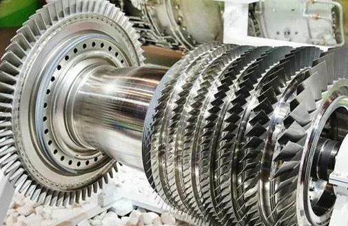
- Rotor: The rotating assembly including shaft, disks, couplings and sometimes integral bladed disks.
- Blade row: Set of blades mounted on a rotor disk; each row has specific modal properties.
- Natural frequency: Frequency at which the system oscillates freely after an initial disturbance.
- Mode shape: Deformation pattern associated with a natural frequency.
- Damping ratio: Measure of energy dissipation; determines decay rate of vibration.
- Critical speed: Rotor speed at which excitation frequency coincides with a lateral natural frequency.
- Resonance: Condition where excitation frequency is close to a natural frequency, producing high response.
Degrees of Freedom in Turbine Systems
Turbine systems are inherently multi-degree-of-freedom (MDOF). A simplified representation typically includes:
- Lateral (bending) degrees of freedom: Horizontal and vertical translations, shaft bending.
- Torsional degrees of freedom: Twisting of the shaft and coupling segments.
- Axial degrees of freedom: Small motions along the shaft axis, often linked with thrust bearings.
- Blade degrees of freedom: Bending in tangential and axial directions, torsion and coupled bending-torsion.
In practice, detailed models can involve hundreds or thousands of degrees of freedom. Reduced-order models are often used for specific analyses such as critical speed evaluation or blade flutter assessment.
Dynamic Behavior of Turbine Rotors
Rotor dynamics focuses on the motion of the shaft and disks supported by bearings and seals. The behavior is governed by mass, stiffness, damping and gyroscopic effects. Rotor dynamics analysis is central to predicting critical speeds, unbalance response and stability.
Lateral Vibration and Gyroscopic Effects
Lateral (flexural) vibration of a rotor is influenced by gyroscopic moments arising from rotation of disks. For flexible rotors with multiple disks, gyroscopic effects split each bending mode into forward and backward precessional modes, each with distinct frequencies.
Typical characteristics include:
- Frequency increase of forward modes with speed.
- Frequency decrease of backward modes with speed.
- Mode shape curvature concentrated near disks and overhung regions.
The rotor equation of motion in matrix form is commonly expressed as:
M·x¨ + (C + G(Ω))·x· + K(Ω)·x = F(t)
where M is mass matrix, C is damping matrix, G(Ω) is gyroscopic matrix, K(Ω) is stiffness matrix (possibly speed-dependent), Ω is rotational speed and F(t) is external excitation such as unbalance or misalignment forces.
Unbalance Response
Rotor unbalance is the most common source of synchronous vibration. It results from mass eccentricity relative to the axis of rotation. The unbalance force is approximately:
Fu = me·e·Ω2
where me is unbalance mass and e is its eccentricity. Synchronous forcing at running speed can excite the first or higher bending modes, depending on the rotor speed range and mode frequencies.
Key aspects include:
- Peak amplitude at or near critical speeds.
- Sensitivity to unbalance distribution along the shaft.
- Influence of bearing stiffness and damping on peak response.
Critical Speeds and Campbell Diagrams
Critical speed analysis identifies rotational speeds where excitation frequencies intersect with rotor natural frequencies. A Campbell diagram (frequency vs rotational speed) is used to visualize these intersections.
In a Campbell diagram:
- Natural frequencies are plotted as functions of speed (including gyroscopic splitting).
- Excitation lines are drawn as multiples of running speed (1×, 2×, 3×, etc.).
- Intersections indicate potential resonance and define critical speeds.
Safe operating regions typically avoid major critical speeds or pass through them with adequate damping and controlled run-up procedures.
Stiff vs Flexible Rotor Classification
Rotor behavior can be classified using the ratio of maximum operating speed Ωmax to first bending critical speed Ωc1:
| Rotor Type | Criterion (Ωmax/Ωc1) | Typical Characteristics |
|---|---|---|
| Stiff rotor | < 0.8 | Operates below first critical; primarily rigid-body behavior |
| Transitional rotor | 0.8 – 1.2 | Operates near first critical; careful balancing and damping required |
| Flexible rotor | > 1.2 | Operates above first critical; multiple mode interactions |
Steam and gas turbine rotors in large power plants are generally flexible rotors that cross one or more critical speeds during run-up and rundown.
Bearing, Seal and Support Effects on Rotor Vibration
Hydrodynamic bearings, seals and structural supports have a decisive influence on rotor vibration and stability. They provide stiffness and damping and can introduce cross-coupled forces that affect whirl stability.
Journal and Thrust Bearings
Journal bearings support radial loads and define lateral stiffness and damping. Their properties depend on clearance, lubricant viscosity, supply pressure and bearing geometry.
Important parameters include:
- Direct stiffness (kxx, kyy) and damping (cxx, cyy) coefficients.
- Cross-coupled stiffness (kxy, kyx) and damping (cxy, cyx).
- Static load capacity and minimum film thickness.
Thrust bearings carry axial loads and constrain axial motion. Axial stiffness affects rotor axial modes and coupling with lateral vibration when labyrinth seals and casings are flexible.
Seals, Cross-Coupling and Rotor Whirl
Labyrinth and honeycomb seals introduce fluid-induced forces that can be destabilizing. Cross-coupled stiffness in seals and bearings can drive forward whirl instabilities, particularly at high speeds and high pressure drops.
Self-excited subsynchronous whirl can occur when cross-coupled stiffness exceeds stabilizing direct stiffness and damping. This is evaluated through stability analysis, including eigenvalues and logarithmic decrement of modes.
Support and Foundation Flexibility
Baseplates, pedestals and foundations have their own natural frequencies and mode shapes. When support frequencies are close to rotor frequencies, coupled modes can develop, altering critical speeds and vibration amplitudes.
Dynamic interaction between rotor and foundation is especially relevant for large turbines installed on flexible structures or with nearby structural resonances in piping and casings.
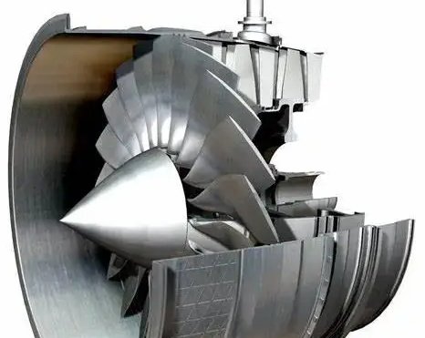
Blade Vibration Characteristics and Mode Shapes
Blades, whether steam, gas or wind turbine blades, are slender, rotating components subjected to complex aerodynamic and centrifugal loads. Their dynamic behavior is characterized by multiple bending and torsional modes that interact with flow disturbances and rotor dynamics.
Principal Blade Modes
For a typical turbine blade, the primary vibration modes include:
- Flapwise bending (out-of-plane, usually in the direction of the main aerodynamic force).
- Edgewise bending (in-plane, tangential to rotation).
- Torsional modes (twisting about the elastic axis).
- Coupled bending-torsion modes for non-symmetric sections.
Each blade mode can be represented by a natural frequency and associated mode shape. In a rotating frame, Coriolis forces and centrifugal stiffening shift these frequencies relative to stationary conditions.
Frequency Distribution Along a Blade Row
In a blade row, small variations in geometry, material properties and attachment conditions cause slight differences in natural frequencies between blades. This frequency spread can be beneficial by reducing synchronous response when excitation is uniform. However, it complicates identification of individual blade resonance and may mask localized defects.
Effect of Rotation: Centrifugal Stiffening
Rotation produces centrifugal tensile stress along the blade span. This increases effective bending stiffness and raises natural frequencies. A simplified relation for a cantilever blade’s bending frequency with rotation can be described qualitatively as:
f(Ω) ≈ f0 · √(1 + β·Ω2)
where f0 is the non-rotating frequency and β is a coefficient representing geometry and material properties. Exact relations require finite element models with rotational effects included.
Excitation Mechanisms in Turbine Rotors and Blades
Understanding excitation sources is essential for predicting resonance and designing for acceptable vibration levels. Rotor and blade excitations are primarily mechanical and aerodynamic, with contributions from electrical and thermal effects in some units.
Mechanical Excitation Sources
Major mechanical sources include:
- Mass unbalance of the rotor and attached components.
- Misalignment of couplings and bearings.
- Mechanical looseness at blade roots or shrouds.
- Gear mesh forces in geared drive systems.
- Rub interactions between rotor and stationary components.
These excitations often produce synchronous (1×) or subharmonic components related to system non-linearities.
Aerodynamic and Flow-Induced Excitations
Aerodynamic forces can excite blades periodically as they pass stationary vanes and flow non-uniformities. The dominant mechanism is the blade passing frequency (BPF):
fBPF = Z · Ω / (2π)
where Z is the number of stator vanes or rotor blades causing periodic pressure fluctuations. Higher harmonics of BPF may also be present due to flow complexity.
Additional aerodynamic excitations include:
- Partial admission effects in steam turbines (only part of circumference admitted with steam).
- Wake interaction between upstream and downstream blade rows.
- Non-uniform inlet conditions and swirl.
- Vortex shedding from blades and struts.
Electrical and Thermal Excitation Influences
In generator-driven turbines, electromagnetic forces can introduce torque ripple and low-level torsional excitations at frequencies linked to electrical grid frequency and harmonics. Thermal gradients can cause differential expansion, rotor bow and slow-time-scale changes in alignment, indirectly altering dynamic response.
Resonance in Turbine Rotors and Blades
Resonance occurs when excitation frequency aligns with a natural frequency of the rotor or blades. It is one of the main concerns in turbine design and operation because it can lead to excessive dynamic stresses and reduced component life.
Rotor Critical Speed Resonance
Passing through a critical speed is common in flexible rotors. During run-up, large vibration amplitudes may be observed near the critical speed. Acceptable operation through resonance requires:
- Adequate damping to limit peak amplitude.
- Controlled acceleration through critical speed to reduce dwell time.
- Proper balancing to minimize unbalance forces.
Critical speeds are identified through analytical modeling and verified by coast-down or run-up tests, monitoring vibration amplitude and phase versus speed.
Blade Resonance and Engine-Order Excitation
Blade resonance is often described using engine orders (EO), where excitation frequency is expressed as a multiple of rotational speed. A blade mode with natural frequency fn can resonate when:
fn ≈ EO · Ω / (2π)
Common EO excitations include:
- Stator vane passing (Zvane order).
- Adjacent blade row interaction orders.
- Partial admission orders in steam turbines.
Resonant conditions are typically visualized on a Campbell diagram including blade natural frequencies and EO lines. Crossing points indicate potential blade resonance.
Coupled Rotor–Blade Resonance
In some cases, rotordynamic and blade dynamic modes can couple through the disk and shaft. This is more probable in integrally bladed rotors (blisks) or slender rotors with significant disk flexibility. Coupled modes can shift frequencies and modify mode shapes, requiring combined rotor–blade finite element models for accurate analysis.
Stability of Turbine Rotors
Stability refers to the tendency of vibrations to decay or grow with time when the system is disturbed. In turbine rotors, instabilities are usually associated with subsynchronous whirl and flutter phenomena driven by cross-coupled forces in bearings, seals and fluid-structure interaction.
Self-Excited Whirl and Logarithmic Decrement
Self-excited whirl arises when non-conservative forces feed energy into a vibration mode. Stability is often evaluated via modal analysis of the linearized system, leading to complex eigenvalues λ = σ ± jω. The real part σ indicates decay (negative) or growth (positive). Logarithmic decrement δ relates to damping ratio and is used as a stability indicator.
A positive or insufficiently negative σ indicates marginally stable or unstable modes, requiring design changes or operational restrictions.
Fluid-Induced Instabilities
In high-speed turbines, fluid forces in seals and bearings can cause:
- Forward whirl instabilities driven by cross-coupled stiffness in seals.
- Oil whirl and oil whip in lightly loaded journal bearings.
Oil whirl typically appears at about 40–50% of running speed, then transitions into oil whip, which locks onto a rotor natural frequency. Sufficient bearing damping, preload and proper geometry are essential for avoiding these phenomena.
Criteria and Margins for Stable Operation
For practical design, standards and guidelines often specify minimum required stability margins. Typical criteria include:
- Minimum logarithmic decrement or damping ratio for critical modes.
- Minimum separation margins between subsynchronous modes and running speed.
- Restrictions on cross-coupled stiffness coefficients in seals and bearings.
Compliance is verified through rotordynamic simulations and, where possible, validated by shop and field tests.
Blade Flutter and Aeroelastic Stability
Blade flutter is a self-excited aeroelastic instability caused by interaction between blade vibration and aerodynamic forces. Unlike forced response resonance, flutter does not require external periodic excitation; instead, flow energy sustains the oscillation.
Mechanism of Blade Flutter
Flutter occurs when aerodynamic forces over a vibration cycle produce net positive work on the blade. The phase relationship between pressure fluctuations and blade motion determines whether the system is stable or unstable.
Key influencing factors include:
- Blade mode shape and nodal diameter pattern across the wheel.
- Reduced frequency and flow Mach number.
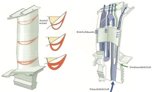
- Stagger angle, chord, twist and airfoil thickness.
- Inter-blade phase angle of vibration.
Flutter Modes and Nodal Diameters
In circular blade rows, vibration patterns are often described by nodal diameters (ND) indicating the number of circumferential nodes. Specific ND patterns can couple strongly with flow, leading to flutter at certain combinations of speed and flow conditions.
Flutter analysis therefore considers multiple mode families and ND patterns, requiring detailed aeroelastic calculations or testing.
Distinguishing Flutter from Forced Response
In practice, high blade vibration levels may be caused by either forced response resonance or flutter. Distinguishing factors include:
- Forced response: Frequency locked to known excitation (e.g., BPF), amplitude related to excitation strength and damping.
- Flutter: Self-excited, frequency near natural frequency, vibration can persist or grow even without clear periodic excitation signature.
Correct identification is critical for selecting appropriate mitigation measures.
Modeling and Analysis Techniques
Accurate modeling and analysis underpin design decisions in rotor and blade dynamics. Approaches range from simplified analytical models to high-fidelity finite element and computational aeroelastic simulations.
Rotor Finite Element Modeling
Rotor finite element (FE) models typically use beam elements for shafts, disk elements for wheels and lumped mass or rigid elements for couplings. Bearings and seals are represented by stiffness and damping matrices derived from hydrodynamic or empirical calculations.
Rotor FE analysis supports:
- Critical speed and mode shape identification.
- Unbalance response prediction at measurement points.
- Stability analysis for subsynchronous modes.
Gyroscopic, spin-softening and centrifugal effects are incorporated for high-speed applications.
Blade Finite Element and Modal Analysis
Blade FE models are built using shell or solid elements to capture complex geometry including airfoil, platform and root. Material properties may be isotropic or anisotropic for composite blades.
Modal analysis provides:
- Natural frequencies in vacuum and in rotating conditions.
- Mode shapes for flapwise, edgewise and torsional modes.
- Strain energy distribution used for assessing local stress concentrations.
Rotating effects are introduced through centrifugal stiffening and Coriolis terms when required.
Campbell and Interference Diagrams
Campbell diagrams plot natural frequencies vs rotational speed together with excitation lines. Interference diagrams focus on relationships between blade natural frequencies and harmonics of running speed, plotted against stage number or rotational speed.
These graphical tools help designers identify unsafe intersections and adjust blade or rotor parameters accordingly.
Frequency Response and Modal Superposition
Frequency response functions (FRFs) quantify system response amplitude and phase as a function of excitation frequency. Using modal superposition, response can be approximated by a sum of contributions from individual modes, simplifying interpretation and enabling efficient parameter studies.
Measurement, Testing and Diagnostics
Experimental methods validate analytical models, support commissioning and aid in troubleshooting abnormal vibration. For turbine systems, both rotor- and blade-focused measurements are used.
Rotor Vibration Measurement Techniques
Common methods include:
- Non-contact proximity probes at bearings to measure shaft relative vibration.
- Casing-mounted accelerometers to measure absolute vibration.
- Keyphasor or once-per-revolution (OPR) signals for phase reference.
Data are analyzed in terms of overall levels, spectra, orbit plots and Bode diagrams (amplitude and phase vs speed) for critical speed identification.
Blade Vibration Measurement Techniques
Blade vibration is more challenging to measure due to high speed and limited access. Techniques include:
- Blade tip-timing (BTT) using arrays of casing-mounted sensors to detect time of arrival variations.
- Strain gauges mounted on blade surfaces, transmitting data via telemetry.
- Optical or laser-based displacement measurements in test rigs.
BTT is widely used in modern turbines to monitor blade resonances, mistuning and flutter indicators during operation.
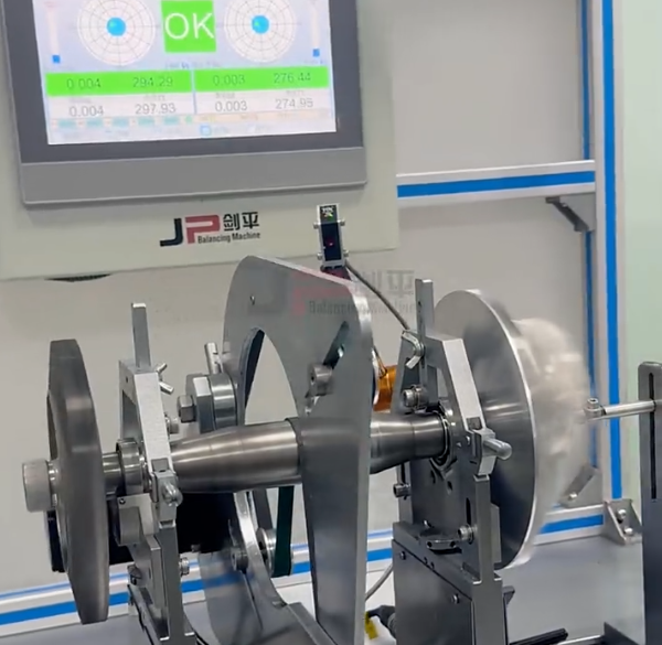
Shop Tests and Field Commissioning
During shop testing:
- Balancing is performed on dedicated balancing machines or in-situ.
- Critical speeds are verified by controlled run-up and rundown, recording vibration response.
- Bearing temperatures, shaft orbits and phase behavior are monitored.
Field commissioning includes alignment checks, verification of vibration limits, bearing performance assessment and confirmation of predicted dynamic behavior under operating load and temperature.
Design Considerations for Vibration and Stability
Designing turbine rotors and blades to meet vibration and stability requirements involves coordinated decisions across mechanical, aerodynamic and system levels.
Material and Geometric Considerations
Material selection affects stiffness, density, damping and fatigue resistance. Typical choices:
- Steel alloys for steam turbine rotors and blades.
- Nickel-based superalloys for high-temperature gas turbine blades.
- Composite or advanced alloys for wind turbine blades and some compressor stages.
Geometric parameters such as blade chord, thickness, twist, platform, shroud and root form influence mode shapes and frequency distributions. Rotor diameter, overhang lengths and disk geometry influence critical speeds and mode separation.
Frequency Placement and Separation Margins
Designers adjust dimensions and mass distribution to place natural frequencies away from dominant excitation frequencies. Specifications typically call for minimum frequency separation margins, for example:
- Bending modes separated by a certain percentage from blade passing frequencies over the operating speed range.
- Torsional modes sufficiently separated from grid frequency and its harmonics.
Multiple iterations of FE analysis are performed to refine frequency placement and verify margins.
Damping Enhancement
Damping reduces vibration amplitudes at resonance and improves stability. In turbines, sources of damping include:
- Material hysteresis.
- Friction in blade roots, shrouds and dovetails.
- Fluid-film damping in bearings and seals.
- External damping devices where applicable.
Damping is usually limited, so accurate estimation is essential when predicting maximum response and stability margins.
Fatigue, Life Assessment and Reliability
Dynamic stresses from vibration contribute to fatigue damage in blades and rotors. Long-term reliability depends on correct assessment of stress cycles and safety factors under actual operating conditions.
Dynamic Stress Evaluation
Dynamic stress is estimated by combining modal strains with response amplitudes. A typical procedure involves:
- Computing mode shapes and local strain distributions using FE.
- Determining vibration amplitudes at critical points from forced response analysis.
- Calculating alternating stresses and comparing with fatigue data.
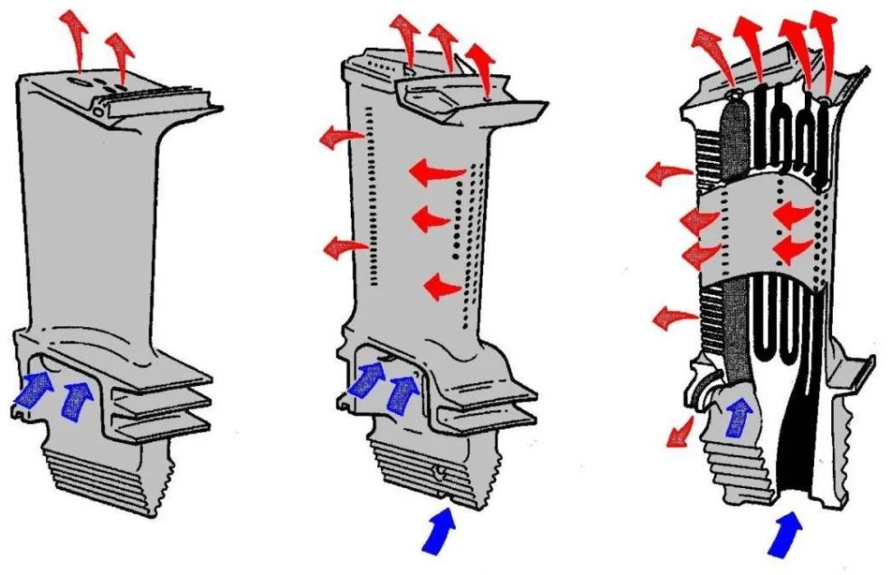
Stress concentration at features such as blade roots, cooling holes and fillets must be accounted for accurately.
Fatigue Damage and Life Prediction
Fatigue life assessment usually uses S–N curves (stress vs number of cycles) and damage accumulation rules. The damage index D is computed as the sum of cycle fractions:
D = Σ (ni / Ni)
where ni is the number of applied cycles at stress level i and Ni is the corresponding number of cycles to failure from S–N data. Acceptable design requires D below specified limits over the intended life.
Inspection and Monitoring for Life Management
Periodic inspection of high-stress components provides feedback for refining life estimates. Non-destructive examination methods include:
- Visual and borescope inspections.
- Dye penetrant, magnetic particle or eddy-current testing for surface cracks.
- Ultrasonic testing for internal defects.
Integrating vibration monitoring with inspection results allows alignment of analytical predictions with observed behavior and supports decisions on refurbishment or replacement.
Practical Issues and Pain Points in Operation
Operating turbines under varying load, temperature and ambient conditions introduces several practical issues directly tied to rotor and blade dynamics. Some of these issues are persistent pain points for operators and maintenance engineers.
Vibration Limits and Protection Systems
Turbine-generator units are equipped with vibration monitoring and protection systems that enforce trip thresholds. Pain points arise when:
- Units repeatedly approach vibration trip limits during load changes or grid disturbances.
- Unbalance or misalignment evolves over time due to thermal distortion or wear.
- Subtle resonances appear after component replacement or modification.
Accurate distinction between acceptable vibration and conditions needing immediate intervention is essential to avoid unnecessary trips while preserving mechanical integrity.
Balancing, Alignment and Maintenance Constraints
Balancing and alignment significantly influence rotor vibration. In large units, achieving optimal balance can be constrained by access, time and operational requirements. Common constraints include:
- Limited opportunities for high-speed balancing.
- Restriction on adding correction weights in certain locations.
- Alignment changes due to gradual foundation settlement and thermal growth.
These practical constraints require careful planning and often iterative adjustments to maintain acceptable vibration over the full operating range.
Mitigation and Control of Vibration and Instability
Mitigation measures aim to keep vibration within allowable limits and ensure stable operation throughout the speed and load range. Actions can be implemented at design stage or during operation and maintenance.
Design-Stage Mitigation Measures
At design time, the most effective measures include:
- Adjusting shaft and disk geometry to shift critical speeds.
- Optimizing bearing and seal geometry for favorable stiffness and damping.
- Refining blade geometry and mass distribution for favorable mode placement.
- Selecting materials and interfaces that provide adequate damping.
Iterative analyses with updated models help converge on a configuration that satisfies all dynamic criteria.
Operational Mitigation and Tuning
During operation, modifications can be applied to address emerging vibration issues:
- Field balancing to reduce synchronous vibration.
- Alignment correction to reduce misalignment forces.
- Seal and bearing modifications to adjust dynamic coefficients.
- Control system adjustments to avoid certain speed ranges during transients.
Continuous monitoring supports early detection of deviations and allows timely interventions before fatigue damage accumulates.
Monitoring and Data-Driven Decision Making
Modern condition monitoring systems provide continuous measurements of rotor and blade vibrations. Combining these data with models and historical records enables:
- Trend analysis and early warning of instabilities or emerging resonances.
- Refinement of rotor and blade models based on operating data.
- Informed scheduling of inspections and maintenance activities.
Reliable monitoring and systematic interpretation of data help maintain safe margins against resonance and instability throughout the turbine life cycle.
Comparative Overview of Rotor and Blade Dynamics Factors
The following table summarizes principal factors affecting rotor and blade dynamics in turbine systems.
| Category | Rotor Dynamics | Blade Dynamics |
|---|---|---|
| Primary Modes | Lateral bending, torsional, axial | Flapwise, edgewise, torsional, coupled |
| Main Excitations | Unbalance, misalignment, fluid-induced forces | Blade passing, wakes, aeroelastic coupling |
| Critical Phenomena | Critical speeds, subsynchronous whirl | Resonant forced response, flutter |
| Key Design Variables | Shaft geometry, disk layout, bearing and seal design | Airfoil shape, chord, thickness, twist, root and shroud |
| Typical Analysis Tools | Rotor FE, Campbell diagrams, stability analysis | Blade FE, aeroelastic analysis, forced response |
| Life-Limiting Mechanisms | Fatigue at stress concentrations, thermal effects | High-cycle fatigue, corrosion and erosion assisted fatigue |
FAQ: Turbine Rotor and Blade Dynamics
What is the difference between rotor critical speed and blade resonance?
Rotor critical speed refers to the shaft speed at which the rotor’s lateral natural frequency coincides with running speed, causing large shaft vibrations due to unbalance. It primarily concerns the global shaft–disk–bearing system. Blade resonance refers to a condition where a blade’s natural frequency matches an excitation frequency such as blade passing frequency. It mainly affects individual blades or blade rows and leads to elevated blade stresses. Both are resonance phenomena but involve different components and frequency ranges.
How can operators detect and manage turbine vibration issues during operation?
Operators rely on permanently installed vibration monitoring systems that use proximity probes and accelerometers to measure shaft and casing vibration. Alarm and trip limits are set based on design criteria and standards. When abnormal vibration is detected, diagnostic tools such as spectra, orbits and trend plots are used to identify the cause, for example unbalance, misalignment or rub. Corrective actions may include adjusting operating procedures, avoiding certain speed ranges, performing field balancing, correcting alignment or inspecting for mechanical damage. Continuous monitoring allows early detection and helps maintain safe operation within vibration limits.
