
Power transmission systems in vehicles and industrial machinery rely heavily on shafts to transfer torque and rotation from one component to another. Among these, the terms transmission shaft and drive shaft are frequently used, sometimes interchangeably, which can cause confusion. This article explains their functions, differences, design parameters, and selection guidelines in a structured and technical way.
Basic Definitions and Roles in the Powertrain
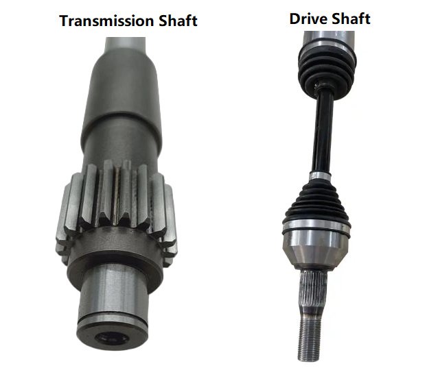
What Is a Transmission Shaft?
A transmission shaft is a general term for any rotating shaft that carries torque and power between components within a power transmission system. In many engineering contexts, it refers to shafts inside a gearbox or transmission assembly, including:
- Input shaft (from engine or motor to gearbox)
- Countershaft or layshaft (carries gearsets inside the transmission)
- Output shaft (from gearbox to downstream components)
In industrial machinery, transmission shafts may connect a motor to a speed reducer, gear train, pulley set, or other drive elements within a relatively compact layout where shaft alignment is fixed and distances are short.
What Is a Drive Shaft?
A drive shaft (also commonly called a propeller shaft or prop shaft in automotive, marine, and aerospace applications) is a specific type of shaft that transfers torque over a distance between components that are not directly adjacent and are often misaligned or moving relative to each other. Typical examples include:
- Automotive: from transmission or transfer case to the front or rear axle
- Marine: from gearbox to propeller
- Industrial: long line shaft connecting motor to remote equipment
Drive shafts usually incorporate flexible joints (universal joints or constant velocity joints) and sometimes slip mechanisms to accommodate angular changes, axial movement, and misalignment between driving and driven units.
Position and Function in Automotive Drivetrains
In vehicles, both transmission shafts and drive shafts are integral to the driveline, but they occupy different positions and perform distinct functions.
Transmission Shafts in Vehicles
Inside a manual or automatic transmission, multiple transmission shafts are arranged to achieve different gear ratios. The primary roles are:
Input shaft: Receives torque from the engine via the clutch or torque converter and feeds it into the gear train.
Countershaft/layshaft: Carries multiple gears that mesh with gears on the main shaft. It determines available gear ratios and often rotates whenever the input shaft turns.
Output or main shaft: Delivers torque, after gear reduction or overdrive, to the drive shaft or final drive assembly.
These shafts typically operate at relatively high speeds with moderate torque and are supported by bearings within a rigid housing, with precise alignment and lubrication controlled by the transmission casing.
Drive Shaft in Vehicles
The drive shaft links the transmission output (or transfer case) to the differential at the axle. Its roles include:
Transmitting engine torque over a relatively long distance to the drive axle, accommodating angular changes due to suspension movement, and allowing axial changes in length due to chassis flex and suspension travel when required.
In rear-wheel drive or four-wheel drive vehicles, the drive shaft is exposed under the vehicle and must work reliably across a range of operating angles, speeds, and loads. It is a critical rotating component whose imbalance or failure can cause vibration, noise, and safety issues.
Typical Configurations: Automotive and Industrial
Automotive Layouts
Depending on drivetrain configuration, the usage of transmission shafts and drive shafts varies:
Front-engine rear-wheel drive:
- Engine crankshaft → clutch/torque converter → transmission input shaft
- Gear sets on transmission shafts → transmission output shaft
- Drive shaft (propeller shaft) → rear differential → rear axle shafts → wheels
Front-engine front-wheel drive:
The gearbox and differential are combined in a transaxle. Internal transmission shafts transfer torque to the differential, and short drive shafts with constant velocity joints connect the transaxle to each front wheel.
Four-wheel drive / all-wheel drive:
Transmission shafts reside inside transmission and transfer case, drive shafts connect the transfer case to front and rear differentials, and smaller axle shafts connect differentials to wheels.
Industrial and Marine Layouts
In industrial applications, transmission shafts typically reside within enclosed gearboxes or between closely spaced components, while drive shafts are used for longer distances or where alignment is variable. In marine propulsion, a gearbox output shaft drives a long propeller shaft (essentially a drive shaft) passing through the hull to the propeller, incorporating couplings, bearings, and seals.
Core Mechanical Differences
Although both types transmit torque, key differences exist in design, duty, and operating environment. The table below summarizes common distinctions.
| Aspect | Transmission Shaft | Drive Shaft (Propeller Shaft) |
|---|---|---|
| Main function | Transfer torque within gearbox or compact powertrain modules, support gearsets | Transfer torque over distance between separated components or axles |
| Typical location | Inside transmission, gearboxes, speed reducers | Outside gearbox, between transmission/transfer case and differential or remote load |
| Torque and speed | Often high speed, moderate torque (varies by gear ratio) | Moderate to high torque, variable speed, subject to angle and length constraints |
| Support and alignment | Precisely supported by multiple bearings in rigid housing; alignment fixed | Supported at ends (and sometimes intermediate support bearing); alignment changes with operation |
| Flexibility requirements | Usually rigid, minimal misalignment allowed | Requires universal or CV joints; often includes slip yoke or spline for length variation |
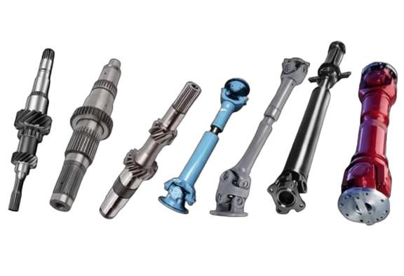
| Structural form | Often solid shaft, multiple gear seats, splines, shoulders | Frequently tubular for weight and inertia reduction; flanges, yokes, joints at ends |
| Loading conditions | Torsion plus bending from gear forces; local stress concentrations at keyways, splines | Primarily torsion plus bending due to self-weight, misalignment, and dynamic effects |
| Exposure | Enclosed, lubricated, protected from environment | Exposed to dust, moisture, road debris, temperature variations |
| Maintenance focus | Bearing and gear wear, lubrication quality | Joint lubrication, balance, corrosion, wear at splines and yokes |
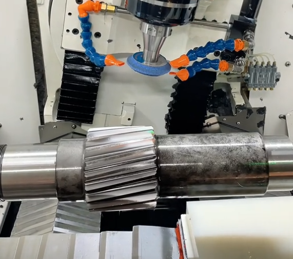
Materials and Manufacturing Approaches
Transmission Shaft Materials
Transmission shafts are commonly manufactured from medium-carbon steels or alloy steels that offer a balance of strength, toughness, and machinability. Typical materials include:
- Medium-carbon steel (e.g., AISI 1045) for general applications
- Alloy steels (e.g., AISI 4140, 4340) for higher torque or demanding conditions
- Case-hardened steels (e.g., 20MnCr5, 16MnCr5) when surface wear resistance and core toughness are both important
Heat treatment processes such as induction hardening, carburizing, quenching, and tempering are used to achieve desired surface hardness on gear seating areas and splines while retaining a ductile core.
Drive Shaft Materials
Drive shafts must combine torsional strength with low mass and good fatigue resistance. Common materials are:
Carbon steel tubing (e.g., low-alloy or micro-alloyed steels) for standard automotive and industrial shafts, aluminum alloys for reduced weight in performance or light-duty vehicles, and fiber-reinforced composites (e.g., carbon fiber) in specialized, high-performance applications.
The shaft is often made as a seamless or welded tube with yokes, flanges, or CV joint housings welded or friction-welded to the ends. Surface coatings or paint protect against corrosion, especially for underbody automotive shafts.
Geometry, Dimensions and Design Parameters
Designing a shaft involves balancing torque capacity, stiffness, critical speed, and manufacturing constraints. Transmission shafts and drive shafts are optimized differently based on their roles.
Length and Diameter
Transmission shafts are relatively short due to the compact gearbox housing, with length-to-diameter ratios often kept low to minimize bending and deflection. They may have stepped diameters to accommodate bearings, gears, and seals.
Drive shafts are usually longer, with length strongly influencing diameter selection. The longer the shaft, the larger the diameter required to maintain stiffness and keep the critical speed above operating speed. Tubular sections are used to increase polar moment of inertia with less weight.
Torque Capacity and Safety Factors
Both types must withstand peak torque conditions such as acceleration, gear changes, and overloads. Design considers:
Nominal and peak torque ratings derived from engine/motor data and gear ratios, material yield and fatigue strength, allowable shear stress for torsion, and appropriate safety factors based on application (e.g., automotive, industrial continuous duty, intermittent duty).
Transmission shafts may also be sized to limit torsional twist to maintain precise gear alignment and engagement, while drive shafts must limit twist to avoid driveline lag and resonance.
Critical Speed and Whirling
Critical speed is particularly important for drive shafts because of their length. Operating speeds should remain significantly below the first critical speed to prevent excessive vibration and potential failure. Transmission shafts, being shorter and more rigid, generally have higher critical speeds relative to operating speed but still need analysis in high-speed applications.
Components and Interfaces
Transmission Shaft Features
Typical features on transmission shafts include stepped diameters for bearings and gears, keyways and splines for torque transmission to gears or hubs, shoulders and snap-ring grooves for axial location, and oil channels or holes for lubrication where required.
These features must be designed with attention to stress concentration, surface finish, and compatibility with mating components. Gear mounting may be via press fit, splines, or integral gear cutting on the shaft itself.
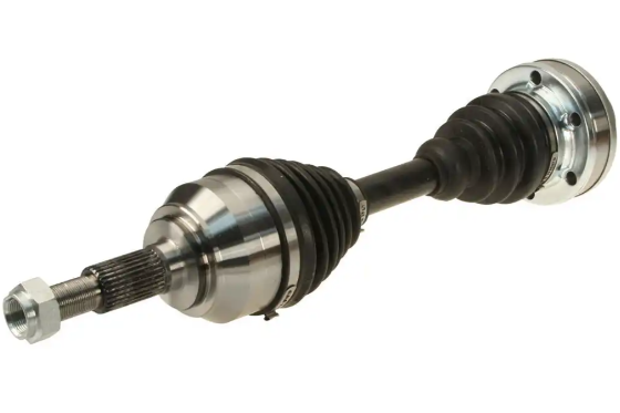
Drive Shaft Features
Drive shafts incorporate end fittings and joints that allow angular and axial movement. Common elements are welded or bolted flanges connecting to transmission output or differential input, yokes for universal joints, CV joint housings with internal bearings, and slip yokes or splined telescoping sections enabling length variation.
Balance weights are typically attached to the tube to correct manufacturing imbalance. Protective boots seal CV joints, and grease fittings may be present on serviceable universal joints.
Joints, Couplings and Alignment Management
Because transmission shafts and drive shafts operate under different alignment conditions, their coupling methods differ substantially.
Transmission Shaft Connections
Within a gearbox, alignment is fixed by the housing and bearing locations. Transmission shafts are usually coupled through gears, clutches, or rigid splined connections. Flexible couplings are rarely required inside a standard transmission since misalignment is minimal.
Drive Shaft Joints
Drive shafts must accommodate angular misalignment between transmission and differential or between differential and wheel hubs. Common joint types are:
- Cross-type universal joints (Hooke joints) for moderate angles and constant average angular velocity
- Double Cardan joints for larger angles with improved angular velocity characteristics
- Constant velocity (CV) joints (e.g., Rzeppa, tripod) for uniform angular velocity at varying angles, critical in front-wheel drive axles
Joint selection depends on angle range, torque capacity, required smoothness, and packaging constraints.
Loading Conditions, Stresses and Failure Modes
Transmission Shaft Loading
Transmission shafts experience combined torsion from transmitted torque and bending from gear mesh forces and shaft weight. Additional local stress arises near keyways, splines, and shoulders.
Potential failure modes include fatigue cracking at stress concentrators, surface pitting or wear at gear seats and bearing contacts, bending deflection causing gear misalignment, and seizure due to lubrication failure or bearing failure.
Drive Shaft Loading
Drive shafts carry torsion from engine output, bending due to self-weight and misalignment, dynamic loads from road irregularities, and impact loads during shifting or sudden traction changes.
Typical failure modes are fatigue cracks in welds, tubes, or yokes; universal joint or CV joint wear and seizure; imbalance-induced vibration leading to accelerated wear; and tube buckling or fracture under severe overload or collision.
Dynamic Behavior, Noise and Vibration
Dynamic performance is crucial for both shaft types but in different ways. In transmission shafts, torsional vibration interacts with gear meshing and can affect noise and gear durability. Design may incorporate tooth modifications, damping through lubricants, and precise tolerances to minimize gear whine.
Drive shafts are more directly involved in vehicle NVH (noise, vibration, harshness). Imbalance, misalignment, or worn joints can cause vibrations felt in the cabin. Designers must control runout, ensure precise balancing, set proper operating angles for universal joints, and avoid operating near critical speed.
Design and Selection Considerations
Selecting or designing transmission shafts and drive shafts requires attention to different priorities. The table below outlines key considerations for each type.
| Consideration | Transmission Shaft | Drive Shaft |
|---|---|---|
| Primary design drivers | Gear arrangement, bearing spacing, housing constraints, gear ratios | Distance between components, operating angles, packaging under vehicle or within system |
| Torsional capacity | Based on engine torque and gear ratios within transmission | Based on torque at axle or driven machinery, multiplied by usage factors |
| Stiffness requirements | Limit deflection to maintain gear alignment and contact patterns | Maintain stiffness to control critical speed and minimize vibration |
| Weight considerations | Important but secondary to strength and precision | Critical, especially in automotive where rotating mass affects response and efficiency |
| Joint and coupling selection | Rigid couplings, splines, clutches within housing | Universal joints, CV joints, flexible couplings, slip joints |
| Environmental factors | Mainly lubrication and temperature inside housing | Exposure to corrosion, dirt, water, temperature swings |
| Maintenance access | Requires opening gearbox or using designed inspection ports | Often accessible from underside or exterior; joints may be serviceable or sealed |
Common Issues and Practical Considerations
When engineers, technicians, or operators address powertrain performance, several practical issues may arise in association with both shaft types.
Wear and Service Life
Transmission shafts are affected mainly by bearing and gear wear, which can alter load distribution and introduce misalignment. Adequate lubrication, clean oil, and correct bearing preload are critical. Drive shafts are more affected by joint wear (universal or CV joints), corrosion, and tube damage from impacts or debris.
Vibration and Noise Complaints
End users often report vibration at certain speeds, droning noises, or clunking sounds. While the root cause may be varied, common contributors include shaft imbalance, worn joints, misaligned components, and improper installation. Correct diagnosis requires checking shaft runout, joint condition, operating angles, and mounting integrity.
Replacement and Interchangeability
Transmission shafts are usually specific to a given gearbox design, with unique gear placements, spline profiles, and lengths. Drive shafts may offer more interchange options but must match length, joint type, torque rating, and flange patterns precisely. Using an incorrect shaft can cause premature failure or unsafe operation.
How to Decide: Transmission Shaft vs Drive Shaft Terminology
In many contexts, both terms refer simply to power transmission shafts. However, in engineering practice, it is useful to keep this distinction:
Transmission shaft: a shaft inside or closely associated with the gearbox or enclosed transmission assembly, primarily responsible for distributing torque among gearsets and internal components.
Drive shaft: a shaft that connects the transmission or transfer case to a remote driven component such as a differential, wheel hub, propeller, or machine input, typically accommodating misalignment and distance.
Using precise terminology helps avoid misunderstandings in design, specification, and maintenance documents and improves communication across engineering, manufacturing, and service teams.
