
Titanium is widely used in aerospace, medical, energy, and high‑performance engineering applications where both high strength and low weight are required. These applications frequently demand tight dimensional control. Understanding what machining tolerances are realistically achievable with titanium, and under which conditions, is essential for cost‑effective and reliable component design and manufacturing.
Overview of Titanium Machining Tolerance Capability
Machining tolerances for titanium depend on alloy, geometry, machine tool, cutting strategy, and inspection capability. In practice, most precision shops operate within a few broad ranges:
- General‑purpose titanium components: ±0.05 mm to ±0.10 mm (±0.002" to ±0.004").
- Precision aerospace and medical parts: ±0.01 mm to ±0.025 mm (±0.0004" to ±0.001").
- Critical features on optimized setups: down to ±0.005 mm (±0.0002") in limited cases.
These ranges are typical for 3‑axis and 5‑axis CNC milling, turning, and related processes using modern equipment, appropriate tooling, and controlled environments. Tolerances significantly tighter than ±0.005 mm are generally associated with special processes (e.g., grinding, honing, lapping) or metrology‑driven finishing rather than standard chip‑removal CNC machining.
Titanium Material Characteristics Affecting Tolerances
The material properties of titanium and its alloys influence how accurately features can be machined and held within tolerance over time.
Elastic Modulus and Springback
Titanium has a lower elastic modulus than steel, which means it is more flexible. During cutting, the workpiece can deflect away from the tool, and thin sections can spring back after the tool passes. This affects:
- Wall and rib thickness: Thin walls tend to be undersized or tapered if cutting forces are not carefully managed.
- Bore diameter and roundness: Bores may slightly spring open after boring operations.
- Flatness and straightness: Long, slender features are susceptible to bending under cutting forces.
Thermal Conductivity and Heat Concentration
Titanium’s low thermal conductivity causes heat to concentrate near the cutting zone and in the cutting edge. Excessive heat can cause local thermal expansion during machining and dimension drift after cooling. Managing temperature is therefore critical to holding tight tolerances, particularly on:
Close‑tolerance fits such as bearing seats, precision bores, and sealing faces.
Processes with high material removal rates or deep cuts in titanium require controlled cutting parameters, effective coolant delivery, and sometimes intermediate stress‑relief or cooling steps to stabilize dimensions.
Work Hardening and Residual Stress
Titanium is prone to work hardening and residual stress accumulation in the surface layer when subjected to aggressive machining conditions, dull tools, or rubbing instead of cutting. This can lead to:
- Tool deflection and micro‑chatter that affect surface finish and tolerance.
- Dimensional changes after roughing as material relaxes.
- Geometrical distortion when thin features are released from clamping.
To achieve and maintain tight tolerances, the machining strategy should minimize work hardening and manage residual stresses through roughing/finishing sequencing and appropriate tool paths.
Common Titanium Alloys and Relative Machinability
Not all titanium alloys behave identically. Alpha‑beta alloys such as Ti‑6Al‑4V Grade 5 are the most common and have well‑understood machinability. Commercially pure (CP) titanium grades generally machine slightly easier but are still more demanding than aluminum or carbon steel. Near‑beta and certain high‑strength alloys can be more difficult to machine consistently to narrow tolerance limits due to increased strength and lower thermal conductivity.
Typical Tolerance Ranges by Process
Different machining processes have different inherent capability for holding tolerances on titanium. The table below summarizes typical achievable ranges under well‑controlled conditions.
| Process | Typical Practical Tolerance Range | Commonly Used For |
|---|---|---|
| CNC Turning (rough to semi‑finish) | ±0.02 mm to ±0.05 mm (±0.0008" to ±0.002") | Shaft diameters, faces, shoulders |
| CNC Turning (finish, rigid setup) | ±0.005 mm to ±0.015 mm (±0.0002" to ±0.0006") | Bearing journals, seal diameters |
| CNC Milling (general 3‑axis) | ±0.02 mm to ±0.05 mm (±0.0008" to ±0.002") | Prismatic features, pockets, bolt patterns |
| CNC Milling (5‑axis, precision) | ±0.01 mm to ±0.025 mm (±0.0004" to ±0.001") | Complex aerospace and medical components |
| Boring (on machining center or lathe) | ±0.005 mm to ±0.015 mm (±0.0002" to ±0.0006") | Accuracy‑critical bores, bearing seats |
| Reaming | ±0.005 mm to ±0.010 mm (±0.0002" to ±0.0004") | High‑precision holes, dowel locations |
| Threading (single‑point or tapping) | Class‑fit dependent; pitch diameter often within ±0.025 mm (±0.001") | Internal and external threads |
| Grinding (where applicable) | ±0.002 mm to ±0.005 mm (±0.00008" to ±0.0002") | Critical diameters, flatness, surface finish |
| Wire EDM (for titanium) | ±0.003 mm to ±0.01 mm (±0.00012" to ±0.0004") | Intricate profiles, tight corner radii |
These ranges assume stable machines, controlled environments, calibrated metrology, and experienced process engineering. For prototype work, small shops, or unfavorable part geometries, actual achievable tolerances may be wider.
Key Factors Influencing Achievable Tolerances
Tolerance capability is not determined by titanium alone. Several controllable process and equipment parameters have a major impact.
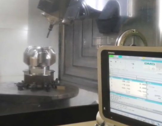
Machine Tool Rigidity and Accuracy
Machine tool design and condition directly affect titanium machining accuracy. Considerations include:
- Spindle and axis rigidity: Heavy‑duty spindles and robust linear guideways reduce deflection under load.
- Axis accuracy and repeatability: Linear scales, high‑resolution encoders, and well‑tuned servo drives improve positioning.
- Thermal stability: Closed‑loop temperature control and solid machine bases limit thermal drift.
High‑precision titanium machining is typically performed on modern CNC machines with advanced control systems, thermal compensation, and periodic alignment checks.
Fixturing and Workholding
Workholding strategy strongly impacts achievable tolerances in titanium. Clamping must be rigid enough to resist cutting forces but not so aggressive that it introduces distortion. Key aspects include:
Location and support of the workpiece to minimize overhangs and slender cantilevered sections.
Distribution of clamping forces to avoid local deformation, especially on thin‑walled or hollow components.
Use of soft jaws, custom fixtures, vacuum fixtures, or modular systems to maximize support in critical regions.
Fixturing strategies often include intermediate machining steps to create reference surfaces before final finishing passes on tolerance‑critical areas.
Tooling, Toolpath, and Cutting Parameters
The cutting tools used for titanium, together with their paths and parameters, have a direct effect on dimensional control:
Specialized carbide grades and coatings suited to titanium help maintain sharp cutting edges and consistent tool behavior over their life.
Toolpath optimization, such as trochoidal milling or constant engagement strategies, reduces load variation, improving dimensional stability.
Appropriate cutting speeds, feeds, and depths of cut reduce heat and deflection. Light finishing passes are preferred for tight tolerances after roughing and semi‑finishing have removed most of the material and stress.
Coolant, Lubrication, and Chip Evacuation
Effective coolant delivery to the cutting zone helps maintain temperature stability, extend tool life, and stabilize dimensions. High‑pressure through‑tool coolant and carefully directed nozzles are common in titanium machining. Adequate chip evacuation avoids recutting and localized heating, which can degrade both finish and tolerance.
Environmental and Thermal Control
Temperature variations in the shop environment, the machine, and the workpiece have a measurable effect on dimensions, especially on long parts or tight tolerance fits. Typical measures include:
Maintaining ambient temperature in a controlled range.
Allowing titanium blanks to reach thermal equilibrium before machining and inspection.
Using in‑process probing and compensation routines to monitor and adjust for thermal drift.
Tolerances for Common Titanium Features
Different geometric features on titanium parts have different typical tolerance capabilities due to their geometry and sensitivity to process variables.
Shafts and External Diameters
Turned titanium shafts and external diameters, when machined on rigid CNC lathes with appropriate tooling, can routinely achieve:
General diameters: ±0.01 mm to ±0.02 mm (±0.0004" to ±0.0008").
High‑precision diameters (e.g., bearing seats): ±0.005 mm to ±0.01 mm (±0.0002" to ±0.0004"), often paired with grinding when requirements approach the lower limit.
Roundness and cylindricity are typically within a few micrometers when finishing strategies are optimized. Clamping method (e.g., collet vs. chuck jaws) and part length‑to‑diameter ratio are important in determining what can be held.
Holes, Bores, and Counterbores
Hole and bore tolerances in titanium depend on the creation method:
Drilling followed by reaming commonly achieves diameter tolerances of ±0.005 mm to ±0.01 mm on stable setups.
Precision boring bars or fine boring heads on machining centers can hold similar or slightly tighter tolerances for critical diameters and alignment.
Positional tolerance of holes relative to datums (true position) depends on machine accuracy and fixturing. Values in the range of 0.01 mm to 0.05 mm are common for precision bolt patterns or dowel holes on high‑end equipment.
Flat Surfaces and Slots
Milled titanium surfaces can achieve:
Overall dimensional tolerances of ±0.02 mm (±0.0008") for general surfaces with good fixturing.
Tighter tolerances down to ±0.01 mm (±0.0004") on limited dimensions when the surface is used as a primary reference and machined with finishing passes.
Flatness and parallelism of machined faces depend on part size and clamping. Smaller surfaces can be kept within a few micrometers, while large plates or frames require careful sequencing and potential stress relief operations.
Thin Walls, Ribs, and Complex Geometries
Thin sections in titanium amplify challenges related to deflection, springback, and heat. Typical titanium components may include pockets with wall thicknesses in the range of 0.5 mm to 2.0 mm. Practical results include:
Wall thickness tolerance often in the ±0.05 mm to ±0.10 mm range for walls around 1.0 mm thick, depending on height and accessibility.
Higher walls or more slender ribs may have more relaxed tolerances or require multi‑step machining with back‑supporting fixtures to maintain form.
In highly optimized aerospace structural parts, design and process engineering are closely coordinated to balance weight reduction with realistic tolerance capability and manufacturability.
Threads and Threaded Features
Internal and external titanium threads are typically produced by single‑point threading, tapping, or thread milling. Practical capabilities include:
Pitch diameter tolerances consistent with standard thread class fits, commonly held within about ±0.025 mm (±0.001") for most sizes.
Functional thread fit is often verified with calibrated GO/NO‑GO gauges rather than relying solely on dimensional measurement.
For critical pressure‑tight or fatigue‑sensitive threaded connections, additional attention is paid to surface finish, root form, and runout, sometimes combining machining with secondary finishing or rolling operations (where applicable to the design).
Surface Finish Requirements and Their Relationship to Tolerances
Tight tolerances are often associated with specific surface finish requirements. For titanium, finish and tolerance interact through tool wear, cutting forces, and post‑processing.
Typical Surface Roughness Values
Common surface finish levels for machined titanium include:
General milled and turned surfaces: Ra 1.6 µm to 3.2 µm (63 to 125 µin).
Precision bearing or sealing surfaces: Ra 0.4 µm to 0.8 µm (16 to 32 µin) after fine turning, boring, or grinding.
Highly polished or functional surfaces (e.g., certain medical or sealing features): Ra below 0.4 µm (16 µin), usually achieved with grinding, polishing, or other finishing steps.
Impact of Finishing Processes on Final Dimensions
Secondary finishing processes such as grinding, polishing, or bead blasting can remove small amounts of material and alter dimensions. When designing and specifying tight tolerances on titanium parts, it is important to consider:
Material allowance for finishing operations.
Potential changes in surface layer stress and how they may influence stability over time.
Sequence of operations so that final tolerance‑critical features are completed after any earlier steps that might distort the part.
Metrology and Inspection for Tight Titanium Tolerances
Accurate measurement is essential to realize and validate tight titanium machining tolerances. The capabilities of inspection equipment and procedures must align with the specified tolerances.
Measurement Equipment and Methods
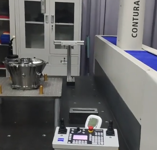
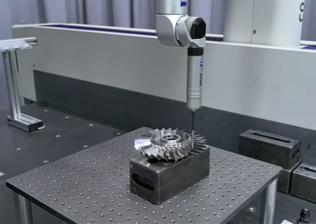
Common metrology methods for titanium parts include:
Coordinate Measuring Machines (CMM): Used for complex geometries, 3D profiles, and GD&T controlled features. Suitable for micrometer‑level accuracy on medium to large parts.
Optical measuring systems and vision machines: Useful for small features, slots, and profiles, especially when non‑contact methods are preferred.
Micrometers, bore gauges, and air gauges: Applied for high‑precision diameters and bores, particularly where tolerances are in the ±0.005 mm to ±0.01 mm range.
Surface roughness testers: Employed to confirm finish requirements alongside dimensional checks.
Environmental Control During Inspection
To maintain correlation between machining and measurement, inspection conditions should be controlled:
Parts are typically inspected at consistent temperature, often around 20 °C (68 °F), and allowed to stabilize before measurement.
Measuring equipment is calibrated and verified on reference artifacts at the same environmental conditions.
For tight tolerances, in‑process inspection using probes or on‑machine measurement routines may be combined with final CMM verification to manage variation and catch deviations early.
Design Guidelines for Specifying Titanium Tolerances
Appropriate tolerance specification is a central element of designing titanium parts for manufacturability and cost‑effectiveness. Overly tight tolerances can significantly increase machining time, tooling cost, fixturing complexity, and inspection effort, without real functional benefit.
Align Tolerances with Functional Requirements
Each dimension should be assigned a tolerance that reflects its functional role in the assembly or system. Dimensions that control fit with mating parts, load paths, sealing interfaces, or critical alignment may justifiably require tighter limits. Non‑functional features, cosmetic surfaces, or non‑contact areas generally do not.
Use GD&T to Communicate Requirements Clearly
Geometric Dimensioning and Tolerancing (GD&T) enables precise definition of form, orientation, and position tolerances for titanium parts:
Position tolerances for holes and pins define allowable variation in a way that often offers more practical freedom than extremely tight linear coordinate tolerances.
Runout, perpendicularity, and parallelism controls help machinists understand which relationships are critical and which are less important.
By focusing tight control only where necessary, GD&T helps optimize cost and achievable accuracy.
Consider Feature Size, Aspect Ratio, and Accessibility
When specifying tolerances for titanium parts, the following geometric aspects influence what is realistic:
Long, slender features are more sensitive to deflection and may require relaxed tolerances or different processes.
Deep pockets or internal features with limited access often have less favorable conditions for coolant flow, tool rigidity, and chip evacuation, affecting achievable accuracy.
Smaller features may require smaller tools that are more flexible, limiting how tight tolerances can be without risk of tool breakage or chatter.
Sequence and Datum Strategy
Well‑planned datums and machining sequences improve tolerance achievement:
Primary datums should be stable, easily accessible, and consistent with assembly references.
Machining from common datums reduces cumulative error for related features, especially in 5‑axis machined titanium components.
Intermediate machining stages may create precision reference surfaces earlier in the process to support later finishing operations.
Cost and Productivity Considerations Related to Tolerances
Tight machining tolerances in titanium are technically achievable but come with clear cost and productivity implications. The link between tolerance and cost is particularly strong because titanium is more demanding to machine than many other engineering metals.
| Tolerance Range (example) | Common Process Implications | Relative Cost Impact |
|---|---|---|
| ±0.05 mm to ±0.10 mm | Standard roughing and finishing; moderate inspection | Baseline |
| ±0.01 mm to ±0.025 mm | Additional finishing passes, higher‑rigidity setups, more precise tooling and fixturing, extended in‑process inspection | Increased machining and inspection cost |
| ±0.005 mm and tighter | Specialized equipment, secondary processes (grinding, lapping), climate‑controlled environment, extensive metrology | Significant cost increase, careful process planning |
For titanium components where weight and performance are critical, tolerances should be set only as tight as required by functional analysis. Relaxing non‑critical tolerances, even slightly, can notably improve machining productivity and reduce scrap risk.
Typical Pain Points When Holding Tight Titanium Tolerances
Manufacturers frequently encounter several practical issues when attempting to hold very tight tolerances on titanium parts:
Dimensional drift between initial machining and final inspection due to stress relief or temperature changes.
Tool wear‑induced variation in size, particularly on long production runs where tool life is a limiting factor.
Distortion of thin features after unclamping from fixturing, especially when only one side has been heavily machined.
Difficulty achieving simultaneous tight geometric control (roundness, cylindricity, flatness) and specific surface finish requirements in a single operation.
These issues are generally addressed through careful process design, conservative finishing passes, tool monitoring, and, when necessary, process qualification runs to validate capability before full‑scale production.
Summary of What Is Realistically Achievable
Titanium machining tolerances are influenced by material behavior, machine capability, tooling, fixturing, temperature control, and inspection methods. Under industrial conditions with appropriate equipment and expertise, the following general conclusions apply:
Standard CNC processes can reliably hold ±0.02 mm to ±0.05 mm for many features on titanium components.
For precision applications, ±0.01 mm to ±0.025 mm is routinely achievable on critical dimensions, given careful process control.
Tolerances around ±0.005 mm are attainable on select features with optimized setups, finishing passes, or secondary processes such as grinding and honing.
Practical tolerance specification should always balance functional requirements with manufacturability, cost, and process capability, taking into account the particular titanium alloy, geometry, and production volume involved.
