
Thin-wall aluminum machining is a core process in aerospace, automotive, medical, and high-performance industrial components. Achieving tight tolerances on low-rigidity parts requires a systematic approach that balances tool selection, fixturing, cutting parameters, and process control. This guide presents a technical and comprehensive overview of best practices for machining thin-wall aluminum parts on modern CNC equipment.
Characteristics of Thin-Wall Aluminum Components
Thin-wall aluminum parts combine low density, high thermal conductivity, and relatively low elastic modulus. These properties provide advantages for lightweight design but introduce specific issues in machining.
Dimensional Definition of Thin Walls
Although definitions vary by industry, thin walls in aluminum are typically characterized by:
- Wall thickness: roughly 0.25–4.0 mm depending on part size and application
- Thickness-to-height (or depth) ratio: often < 1:10, sometimes < 1:20
- Stiffness dominated by wall geometry rather than bulk material
For accurate process planning, it is useful to classify regions by stiffness rather than simple thickness alone, considering wall length, boundary conditions, and local features such as ribs, bosses, and pockets.
Material Behavior Relevant to Machining
Common aluminum alloys used for thin-wall parts include 6061-T6, 7075-T6, 2024-T3/T4, 7050, and various cast and wrought aerospace grades. Key behavior affecting machining:
- High thermal conductivity: promotes heat dissipation into chips and tool, supporting high cutting speeds when cooling is well controlled.
- Lower modulus than steel: increases susceptibility to deflection, chatter, and elastic recovery after cutting.
- Tendency to form built-up edge (BUE): especially in softer alloys if cutting edges are not sharp or cutting speed is too low.
Understanding these characteristics helps in selecting tools, coatings, and cutting strategies that minimize deformation and surface defects.
Key Pain Points in Thin-Wall Aluminum Machining
Thin-wall aluminum machining involves several recurring technical difficulties that must be addressed systematically.
Deflection and Dimensional Inaccuracy
The low stiffness of thin sections leads to part and tool deflection under cutting forces. This produces:
- Out-of-tolerance wall thickness and flatness
- Tapered walls due to varying deflection over depth
- Rebound marks when material elastically recovers after the tool passes
Managing radial and axial cutting forces is critical to avoid these issues.
Chatter and Poor Surface Finish
Thin walls act as flexible plates that easily vibrate. When combined with long tool overhangs, this generates chatter and surface waviness. Chatter increases tool wear and can force conservative cutting parameters if not properly controlled through fixturing, tooling, and strategy.
Distortion After Unclamping
Residual stresses in the workpiece blank and non-uniform material removal can cause the thin walls to move after unclamping. Distortion may not be visible while the part is clamped, but dimensional checks after release show bending or twisting. Proper stock removal sequence and fixturing help minimize this effect.
Material and Blank Preparation
Before programming and machining, careful selection and preparation of aluminum stock is essential for stable thin-wall machining.
Alloy and Temper Selection
Where design allows, select tempers and alloys that balance strength with machinability:
- High-strength alloys such as 7075-T6 and 2024-T3 are common in aerospace components and generally machine well with appropriate tools and conditions.
- Softer alloys or low-temper conditions can increase adhesion and BUE, requiring sharper tools and higher cutting speeds.
The chosen alloy should be consistent with design requirements while considering chip formation and surface quality.
Stress-Relieved Stock
Residual stress in plate, bar, or forged stock is a major contributor to distortion. Using stress-relieved or stretched plate and properly normalized forgings reduces deformation after roughing and finishing. Where possible:
- Specify stress-relieved material condition in purchasing documentation.
- For critical parts, consider intermediate stress relief or roughing passes with rest periods before finishing.
Blank Configuration and Stock Allowance
Blank geometry and stock allowance affect stiffness during machining:
- Leave sufficient stock on thin areas during roughing to maintain rigidity for later finishing.
- Avoid excessive stock that amplifies residual stress release during heavy material removal.
- Use sacrificial ribs or tabs designed into the blank that are removed in final operations to support walls through most of the process.
Fixturing and Workholding for Thin Walls
Fixturing is a primary factor in the success of thin-wall aluminum machining. Fixtures must support the part without distorting it, while allowing full tool access and efficient chip evacuation.
Fundamental Fixturing Principles
For thin-wall parts, fixturing should:
- Maximize support contact surfaces, especially under walls that will be thinned later.
- Restrain all necessary degrees of freedom with minimum clamping force to avoid local deformation.
- Place clamps over bulkier regions, not over thin sections or close to finished thin walls.
- Maintain repeatable and stable datum references for multi-setup machining.
Vacuum Fixtures and Custom Supports
Vacuum fixtures are widely used to support thin plates and pockets, especially in aerospace components. Key aspects:
- Use properly sized vacuum zones to maintain holding force as areas are cut through.
- Incorporate mechanical stops or locators to prevent sliding under cutting forces.
- Use soft seals and flat reference surfaces to avoid local imprinting or distortion.
Custom supports such as form-fitting nests, soft jaws, and modular supports can be used to match complex 3D geometries. In many cases, additive-manufactured fixtures or machined sacrificial fixtures provide full backside support.
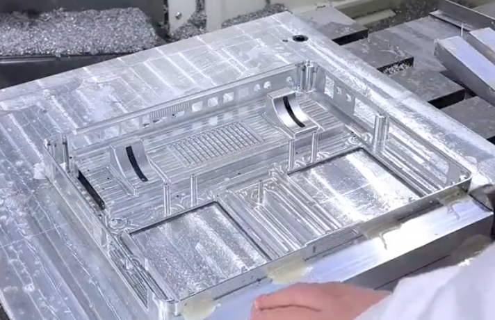
Use of Sacrificial Ribs and Tabs
Sacrificial ribs, webs, and tabs temporarily increase stiffness and support during machining. Recommendations:
- Design ribs that connect thin walls to more rigid regions and remove them in final operations.
- Ensure rib removal operations are accessible and do not introduce new distortion.
- Control rib width and height to balance support with additional machining time.
Tooling Selection for Thin-Wall Aluminum
Tool geometry, material, and coating have a direct impact on cutting forces, surface quality, and the risk of chatter when machining thin-wall aluminum parts.
Tool Material and Coatings
Carbide tools are standard for aluminum machining due to their stiffness and wear resistance at high cutting speeds. Considerations:
- Uncoated or polished carbide is effective for many aluminum alloys, reducing built-up edge.
- PVD coatings specifically formulated for aluminum (e.g., TiB₂ or other low-adhesion coatings) can reduce sticking and improve tool life, especially in high-speed milling.
- Avoid coatings designed for ferrous materials that may increase friction or chip welding on aluminum.
Geometry: Flutes, Helix, and Edge Preparation
Typical best practices include:
- Use 2–3 flute end mills for slotting and roughing to enhance chip evacuation at high feed per tooth.
- Use 3–5 flute end mills for finishing to increase tooth engagement while maintaining chip space.
- Select high helix angles (e.g., 35–55°) to promote smooth cutting and chip evacuation, but balance this with axial force that may pull the tool or workpiece.
- Use sharp cutting edges and small edge hone to minimize cutting forces and elastic deformation of thin walls.
Tool Diameter, Length, and Overhang
Tool stiffness is proportional to diameter and inversely related to the cube of overhang. For thin-wall machining:
- Use the largest practical tool diameter that fits the geometry.
- Minimize stick-out; adjust tool length just beyond the depth requirement.
- Use necked tools where necessary, with reinforced shank to maintain stiffness while providing reach.
| Operation | Tool Type | Flutes | Helix Angle | Key Consideration |
|---|---|---|---|---|
| High-volume roughing | Carbide end mill, variable pitch | 3 | 35–45° | Balance chip load and reduced radial engagement |
| Slotting/thin rib roughing | Carbide end mill, robust core | 2–3 | 35–45° | Maximize chip evacuation and stiffness |
| Wall finishing | Carbide finisher, sharp edge | 3–5 | 40–55° | Low cutting force for minimal deflection |
| Floor finishing | Flat end mill or face mill | 3–6 | 30–45° | Stable contact to achieve flatness |
| Thin pocket corners | Small diameter end mill | 2–3 | 35–45° | Maintain minimal overhang and reduce radial engagement |
Cutting Parameters and Force Control
Cutting parameters for thin-wall aluminum must be selected to minimize radial and axial forces, while maintaining stable chip formation. The goal is to reduce deflection and chatter, not simply to maximize metal removal rate.
Cutting Speed (Vc)
Aluminum permits very high cutting speeds. Typical ranges for carbide tools:
- General milling: approximately 300–900 m/min, depending on alloy, tool diameter, and machine capability.
- Finishing of thin walls: often towards the upper range to promote clean cutting and reduce BUE, provided cooling is adequate.
Higher cutting speed can reduce cutting forces but may increase thermal load; proper coolant use is important.
Feed per Tooth (fz) and Chip Load
Feed per tooth must be sufficient to avoid rubbing but not so high that cutting forces deflect thin walls. Typical guidelines for carbide tools in aluminum:
- Roughing: approximately 0.05–0.25 mm/tooth depending on tool diameter and rigidity.
- Finishing thin walls: approximately 0.02–0.10 mm/tooth, often favoring the lower part of this range.
Always validate fz based on tool manufacturer recommendations and actual machine-tool-part system stiffness.
Radial and Axial Depth of Cut
Reducing radial engagement while increasing axial engagement is a common strategy in thin-wall aluminum machining:
- Radial depth (ae) for finishing thin walls is often limited to 2–10% of tool diameter to restrict radial force components.
- Axial depth (ap) can be larger, sometimes up to the full wall height for well-supported sections, but may need to be split into multiple passes for very thin or flexible walls.
In practice, multiple light radial passes are used to bring walls to final thickness, with a consistent toolpath that minimizes entry and exit force variations.
Toolpath Strategies for Thin-Wall Aluminum
Toolpath strategy strongly influences cutting force direction, heat input, and vibration tendencies in thin-wall machining. Effective strategies are oriented towards consistent engagement and load control.
Climb Milling vs. Conventional Milling
Climb milling (down-milling) is generally preferred for aluminum due to better surface finish and lower cutting forces when the machine has minimal backlash. For thin walls:
- Use climb milling to promote stable cutting and consistent chip formation.
- Consider conventional milling only in specific cases where tool deflection pushes the wall against a rigid support.
Step-Over, Step-Down, and Multiple Passes
Thin-wall finishing benefits from multiple light passes:
- Use small step-over to reduce instantaneous radial load.
- Leave a small, uniform finishing allowance after roughing to maintain rigidity.
- Finish walls in several progressively lighter passes, especially for very thin or tall walls.
This approach reduces risk of wall vibration and helps maintain dimensional consistency from top to bottom.
High-Speed and Trochoidal Toolpaths
High-speed machining (HSM) and trochoidal toolpaths maintain constant engagement and reduce peak forces:
- Apply adaptive clearing or similar strategies in roughing to keep radial engagement low and speed high.
- Avoid sharp changes in direction that cause impulsive loading on thin walls.
- Use smooth entry/exit paths to minimize force peaks at the beginning and end of tool engagement.
Minimizing Deformation and Residual Stress Effects
Deformation management for thin-wall aluminum parts requires an integrated plan combining machining sequence, stock removal patterns, and fixture strategy.
Machining Sequence and Intermediate Steps
Best practices include:
- Rough all sides to a balanced condition before finishing any single thin-wall area.
- Alternate machining of opposite sides or symmetric regions to minimize unbalanced stress.
- Use semi-finishing passes to stabilize geometry before final finishing passes.
In some applications, leaving temporary supporting features, machining them away late in the process, and applying local re-finishing passes is effective.
Balanced Material Removal
Uneven material removal releases residual stresses unevenly and can bend thin walls. Techniques to reduce this:
- Plan material removal in layers, maintaining similar thicknesses on opposing sides where possible.
- Avoid deep isolated pockets in an otherwise solid region; instead, rough multiple pockets in stages.
- When machining large plates, distribute roughing operations so no area is fully finished while others remain uncut.
Chatter Control and Vibration Management
Chatter mitigation requires attention to both the machine-tool system and the part stiffness. Thin walls amplify vibration if the conditions fall within unstable regions.
Machine and Toolholder Considerations
To improve dynamic stability:
- Use high-stiffness toolholders (e.g., shrink-fit or hydraulic chucks) with minimal overhang.
- Avoid unnecessary extensions, reducers, or adapters that reduce system rigidity.
- Operate within speed ranges proven to be stable for a given tool–holder–machine combination.
Optimizing Cutting Conditions for Stability
When chatter appears:
- Adjust spindle speed to move away from the chatter frequency; sometimes moderate speed changes are sufficient.
- Reduce radial engagement to lower cutting forces and vibration amplitude.
- Consider using variable-pitch or variable-helix tools, which can break up resonance conditions.
Process monitoring using spindle load or vibration sensors can help detect and correct unstable conditions early.
Coolant, Lubrication, and Chip Evacuation
Effective cooling and chip removal are important for surface quality, dimensional control, and tool life in thin-wall aluminum machining.
Coolant Types and Application
Common options include flood coolant, minimum quantity lubrication (MQL), and air blast:
- Flood coolant is widely used and effective in removing heat and lubricating the cutting zone.
- MQL can be suitable for high-speed milling where thermal control and environmental considerations are important.
- High-pressure air or coolant jets help evacuate chips from deep pockets and thin slots.
For thin walls, ensuring that coolant or air does not introduce significant pressure on flexible surfaces is important to avoid vibration or deflection.
Chip Evacuation in Thin Features
Aluminum chips can pack into thin slots or undercut regions. To avoid chip-related damage:
- Use toolpaths that encourage chips to exit away from walls rather than trapping them between tool and workpiece.
- Avoid excessive plunge cutting into confined spaces; use ramp or helical entries when possible.
- Monitor for chip re-cutting, which degrades surface finish and accelerates tool wear.
Inspection, Measurement, and Process Verification
Thin-wall components require careful dimension and geometry verification due to the sensitivity of walls to handling and residual stress.
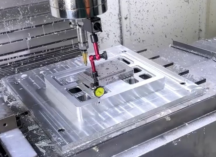
On-Machine and In-Process Measurement
In-process measurement can detect deviation early and guide corrective actions:
- Use spindle-mounted probes to verify critical dimensions and datum locations after roughing and semi-finishing.
- Measure wall thickness in accessible locations and adjust tool offsets as needed before final finishing passes.
- Integrate probing cycles into the CNC program for repeatable process validation.
Post-Process Inspection of Thin Walls
After unclamping, thin walls may move slightly. Inspection methods include:
- Coordinate measuring machines (CMM) with low probing force to avoid deforming thin sections.
- Non-contact methods such as optical measurement or laser scanning for very flexible surfaces.
- Wall thickness inspection using ultrasonic gauges or calibrated measuring instruments designed for thin features.
| Inspection Aspect | Method | Key Advantage | Consideration |
|---|---|---|---|
| Dimensional accuracy | CMM (contact) | High precision, full 3D capability | Low probing force required for thin walls |
| Surface geometry | Optical scanner | Non-contact, fast coverage | Requires surface preparation for reflective aluminum |
| Wall thickness | Ultrasonic thickness gauge | Works on one-sided access | Calibration and coupling medium needed |
| Flatness and waviness | Surface plate plus dial gauge | Simple and reliable | Limited to accessible regions |
Process Planning for Thin-Wall Aluminum Components
Successful thin-wall aluminum machining depends on integrated process planning that coordinates design, fixturing, tools, and CNC programming.
Design for Manufacturability Considerations
While design requirements often dictate thin walls, some parameters can still be optimized for machinability:
- Avoid unnecessary wall height or abrupt transitions in thickness where tolerances allow.
- Use fillets at internal corners to permit larger tool diameters and reduce stress concentration.
- Allow appropriate tolerances on non-critical surfaces to reduce the need for extremely light finishing passes.
Simulation and Toolpath Verification
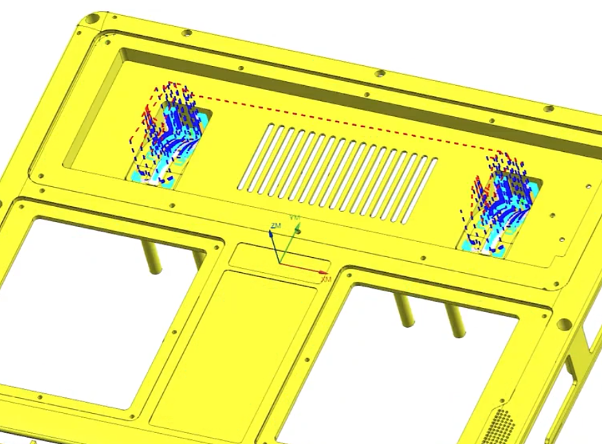
CAM simulation and verification are important to avoid unexpected forces and collisions:
- Use material removal simulations to visualize remaining stock and wall thickness progression.
- Check for excessive tool engagement in thin regions; adjust paths and parameters accordingly.
- Verify tool–fixture–part clearance for all 5-axis or multi-setup operations.
