
Surface finish is a critical characteristic in manufacturing that affects the performance, appearance, and cost of components. This guide explains key surface roughness parameters, major finishing processes, relevant standards, inspection methods, and typical cost relationships to support design, procurement, and process planning decisions.
Fundamentals of Surface Finish and Roughness
Surface finish describes the texture of a surface at a microscopic scale. It is usually characterized by a combination of roughness, waviness, and lay (direction of the predominant pattern). In most engineering specifications, the focus is on roughness because it strongly influences friction, wear, sealing, and fatigue behavior.
Surface texture components
- Roughness: Fine, closely spaced deviations from the ideal surface, typically created by manufacturing processes such as turning or grinding. Roughness is usually quantified with parameters like Ra and Rz.
- Waviness: Larger-spaced deviations due to machine vibrations, deflection, or thermal distortion. Waviness is measured over longer sampling lengths and can affect sealing and contact stiffness.
- Lay: Direction of the predominant surface pattern, determined by the tool path or process mechanics. Lay is important for tribological applications such as bearings and seals.
Common roughness parameters and typical ranges
Multiple roughness parameters exist, but a small set is widely used in mechanical drawings and specifications. The table below summarizes key parameters and typical value ranges for engineered surfaces.
| Parameter | Description | Typical range for engineering surfaces | Common applications |
|---|---|---|---|
| Ra (µm) | Arithmetic average of absolute profile deviations from the mean line over the evaluation length. | 0.025–6.3 µm (1–250 µin) | General specification for machined, ground, or polished surfaces. |
| Rz (µm) | Average peak-to-valley height, typically average of the five highest peaks and five deepest valleys within the evaluation length. | 0.1–25 µm | Bearing surfaces, sealing surfaces, where peak-to-valley height is critical. |
| Rt (µm) | Total height of the roughness profile, from the highest peak to the lowest valley within the evaluation length. | 0.5–80 µm | Surfaces subject to coatings, adhesive bonding, and fatigue-sensitive areas. |
| Rq (µm) | Root-mean-square (RMS) roughness; more sensitive to high peaks and deep valleys than Ra. | 0.03–8 µm | Optical components, precision surfaces, and legacy specifications. |
| Sa (µm) | Area-based analog of Ra, measured over a 3D surface instead of a line profile. | 0.01–5 µm | Freeform surfaces, additive manufacturing, complex geometry functional surfaces. |
Ra and Rz are the most commonly used parameters in mechanical drawings. Ra provides a simple averaged measure, while Rz and Rt are more sensitive to isolated defects such as scratches or pits.
Surface finish vs dimensional accuracy
Surface finish and dimensional tolerances are different but related aspects. A part can have tight dimensional tolerances but still have a relatively rough surface, or vice versa. Finishing operations often improve both, but finer finishes may not always be necessary to meet dimensional requirements. When specifying both, it is important to avoid conflict, such as a very tight size tolerance combined with an unnecessarily fine finish on noncritical faces, which can significantly increase cost.
Types of Surface Finishes by Manufacturing Process
Most surfaces are created or refined through mechanical, chemical, or electrochemical processes. Each process produces a characteristic texture, achievable roughness range, and cost profile. Selecting the appropriate process depends on material, geometry, functional requirements, and production volume.
Machined finishes (turning, milling, drilling)
Conventional machining is often the initial step that generates the base surface. Tool geometry, feed rate, cutting speed, depth of cut, and machine rigidity all influence the final texture.
Typical Ra ranges:
- Rough turning: about 3.2–12.5 µm Ra
- General finishing with carbide tools: about 0.8–3.2 µm Ra
- Fine turning with optimized conditions: about 0.4–0.8 µm Ra
Machined surfaces usually have directional lay aligned with the tool path. For sealing surfaces or sliding bearings, additional finishing such as grinding or honing is often required to achieve lower roughness and a more controlled profile.
Grinding and superfinishing
Grinding uses an abrasive wheel to produce precise geometry and improved surface finish. It is widely used on hardened steels and precision components.
Indicative roughness levels:
• Surface grinding: around 0.2–1.6 µm Ra, depending on wheel and parameters
• Cylindrical grinding: around 0.1–0.8 µm Ra
• Superfinishing (e.g., micro-honing or superfinishing stones): around 0.02–0.2 µm Ra
Grinding can produce cross-hatched or unidirectional lay patterns. It is commonly specified for bearing journals, shafts, valve components, dies, and mold inserts. Superfinishing further reduces asperity heights and improves contact performance, especially in high-speed or high-load tribological applications.
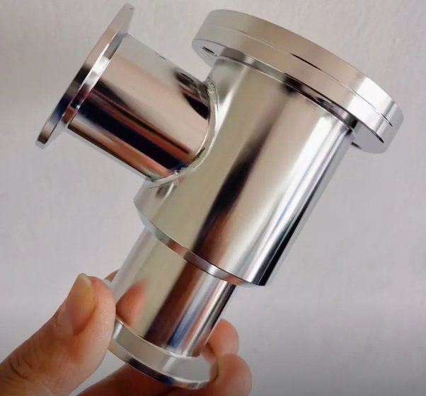
Polishing and lapping
Polishing uses fine abrasive media (wheels, belts, or compounds) to smooth surfaces, often improving appearance and reducing roughness beyond what grinding can achieve. Lapping uses loose abrasive between the workpiece and a flat lap plate for highly accurate, extremely smooth surfaces.
Typical roughness levels:
• Mechanical polishing: around 0.05–0.4 µm Ra (depending on sequence of grits)
• Precision lapping: around 0.01–0.1 µm Ra, with very high flatness
• Optical polishing: down to 0.005 µm Ra or lower on selected materials
Polishing directions and sequence influence the final lay and possible micro-scratches. For functional surfaces, the process must be controlled to avoid rounding critical edges or changing dimensions outside tolerance.
Honing and bore finishing
Honing is used for internal cylindrical surfaces such as engine cylinders, hydraulic cylinders, and precision bores. It removes small amounts of material with an abrasive stone that reciprocates and rotates to form a controlled cross-hatch pattern.
Typical roughness levels:
• Honed bores: about 0.1–0.8 µm Ra, depending on application
• Fine hydraulic or pneumatic cylinders: often 0.1–0.4 µm Ra
The cross-hatch angle and profile are important for oil retention in lubricated systems. An optimized plateau-honed surface has reduced peak heights and additional micro-valleys for lubricant storage, improving wear and friction behavior.
Shot blasting, sandblasting, and peening
Abrasive blasting propels particles at the surface to clean, texture, or strengthen it. Sandblasting and bead blasting typically increase roughness and create a matte appearance, while shot peening primarily induces beneficial residual compressive stresses.
Typical effects:
• Ra often in the range of 1.6–12.5 µm or higher, depending on media size and pressure
• Surface becomes nondirectional or randomly textured
• Oxides, scale, and contaminants are removed, improving coating adhesion
Shot peening may slightly increase roughness but is mainly used for fatigue life improvement by compressive stress introduction in highly stressed components such as springs, gears, and turbine blades.
Chemical treatments and pickling
Chemical pickling and etching remove surface oxides or a thin metal layer using acids or alkaline solutions. These processes clean the surface and may slightly modify roughness, depending on the initial condition and exposure time.
Effects on roughness:
• If the starting surface is smooth, pickling can increase micro-roughness due to selective attack on microstructural features.
• For heavily scaled or corroded surfaces, overall appearance and local roughness may improve after removal of loose layers.
Control of exposure time, concentration, and temperature is important to avoid excessive material loss or surface pitting.
Coatings and plating finishes
Coatings such as electroplating, electroless plating, anodizing, and paints can significantly alter the surface finish and are frequently specified for corrosion protection, wear resistance, or aesthetics.
General behaviors:
• Electroplating (e.g., nickel, chrome, zinc): tends to replicate the underlying roughness; very thin coatings do not eliminate machining marks.
• Electroless nickel: provides uniform thickness; can smooth micro-roughness slightly but usually still follows the base profile.
• Anodizing of aluminum: increases hardness and introduces micro-porosity; visual appearance can be smooth or matte depending on pre-treatment.
• Paint and powder coat: can cover minor imperfections but still reflect underlying waviness and major profile deviations.
For critical surfaces, the substrate finish is usually specified before coating, along with coating thickness and any post-treatment (e.g., polishing of hardened chrome plating).
Surface finishes in additive manufacturing
Additive manufacturing (AM) processes, including powder bed fusion and material extrusion, often produce relatively rough surfaces with step-like features. Typical as-built roughness can be in the range of 5–25 µm Ra on sidewalls, sometimes higher depending on material and process.
To meet functional requirements, AM parts frequently undergo secondary finishing such as machining, grinding, tumbling, blasting, or chemical smoothing. When specifying finishes for AM parts, it is common to distinguish between critical surfaces (e.g., mating faces) that will be post-machined to conventional roughness levels and noncritical surfaces left in as-built or minimally treated condition.
Surface Finish Standards and Symbols
Standardization of surface finish terminology and symbols enables clear communication between designers, manufacturers, and inspection personnel. Several international and national standards define texture parameters, measurement conditions, and drawing indications.
Key international standards
Several widely adopted standards govern surface texture measurement and specification:
• ISO 4287: defines profile roughness parameters such as Ra, Rz, Rq, and others.
• ISO 4288: describes rules and procedures for roughness measurement, including sampling lengths and evaluation lengths.
• ISO 1302: defines graphical symbols for indicating surface texture on technical drawings and how to specify requirements such as machining allowance, lay, and surface integrity.
• ASME B46.1: defines surface texture in North America, including profile and area parameters, measurement methods, and related definitions.
These standards specify how to choose cut-off wavelengths, filter types, and evaluation lengths, which is essential for obtaining comparable results between different instruments and laboratories.
Surface finish symbols on drawings
On engineering drawings, surface texture requirements are indicated using standardized symbols and annotations. The basic symbol resembles a check mark or a right angle with a short upper bar. Additional modifiers provide more information:
• Basic symbol: indicates a surface with specified texture requirement without indicating method of production.
• Symbol with a bar: can indicate that material removal is required (machining) or not permitted, depending on standard variant.
• Numerical value: typically placed near the symbol (e.g., Ra 1.6) to specify required roughness in micrometers or microinches.
• Additional text: may specify parameter type (e.g., Rz), machining allowance, or special conditions.
• Lay symbol: pairs of lines or graphical patterns may indicate lay direction, such as parallel, perpendicular, crossed, or multidirectional relative to the drawing surface.
When multiple surfaces share the same requirement, a general note may specify a default surface finish (e.g., “Unspecified surfaces: Ra 3.2 µm max”), reducing drawing clutter. Critical surfaces may then be individually annotated with finer or distinct requirements.
Roughness grades and comparison scales
In some contexts, roughness grades or N-numbers (e.g., N1–N12) are used to classify finishes. Each grade corresponds to a range of Ra values. For example, very fine lapped surfaces correspond to low N numbers, while rough cast surfaces correspond to high N numbers. Physical roughness comparison specimens made of steel or other materials allow operators to estimate surface finish tactilely or visually when precise measurement is not required.
Functional Requirements and Surface Finish Selection
Surface finish influences component performance across multiple domains, including wear, friction, fatigue, sealing, and appearance. Selecting an appropriate roughness level requires understanding functional needs and process capability, not simply aiming for the lowest possible Ra.
Wear and friction behavior
In sliding contacts, roughness affects the real area of contact, lubrication regime, and wear mechanisms. A surface that is too rough may cause abrasion, high friction, and rapid wear, whereas an extremely smooth surface can impede lubricant film formation in some cases.
Typical guidelines:
• Lightly loaded sliding with boundary lubrication: moderate roughness (e.g., 0.2–0.8 µm Ra) with a controlled profile and lubricant pockets can be beneficial.
• Rolling bearings and precision guides: require low roughness on both races and rolling elements, typically in the 0.05–0.2 µm Ra range, combined with rigorous cleanliness and hardness requirements.
• Dry sliding contact: roughness must be matched to material pairing to control friction and avoid galling or adhesion.
Sealing surfaces and leakage control
Sealing applications such as flanges, O-rings, mechanical seals, and hydraulic interfaces are highly sensitive to surface finish. Roughness must be low enough to prevent leakage paths but not so low that gaskets or seals fail to conform.
Typical ranges (indicative, subject to specific design and materials):
• Soft gaskets on flanges: often around 3.2–6.3 µm Ra to promote gasket “bite.”
• O-ring grooves: about 0.8–1.6 µm Ra in many applications.
• Precision metal-to-metal seals: may require 0.1–0.4 µm Ra or better, with controlled waviness.
In addition to Ra, parameters related to peak distribution and waviness may be critical. Surface defects such as scratches, chatter marks, or pits can cause leaks even if the average roughness is within tolerance.
Fatigue strength and surface integrity
Surface finish influences fatigue life because cracks often initiate at surface irregularities. Deep scratches, machining marks, and residual tensile stresses can significantly reduce fatigue strength. Processes like grinding, shot peening, and fine polishing can improve fatigue life when properly controlled.
Important considerations:
• Lower roughness reduces stress concentration at peaks.
• Residual compressive stresses at the surface (from peening or controlled finishing) enhance fatigue resistance.
• Burn marks, microcracks, or white layers from abusive grinding can be detrimental even if roughness appears acceptable.
Corrosion and coating adhesion
Surface finish also affects corrosion behavior and the performance of protective coatings.
Effects include:
• Very rough surfaces can trap corrosive media and accelerate localized attack.
• Slight roughening can improve mechanical interlocking and adhesion of paints, adhesives, and some coatings.
• Polished surfaces can delay initiation sites for pitting in certain stainless steels but may require activation or roughening for coating adhesion.
Pre-treatment sequences often include cleaning, blasting, or chemical conditioning to achieve a defined surface profile before coating, frequently specified in terms of profile height or equivalent roughness.

Measurement and Inspection of Surface Finish
Reliable assessment of surface finish is essential for quality control, process validation, and functional verification. Different measurement techniques offer trade-offs between accuracy, speed, and suitability for production environments.
Contact profilometers
Contact stylus profilometers are widely used due to their robustness and well-defined measurement principles. A diamond-tipped stylus is drawn across the surface under controlled force, and vertical motion is recorded to create a profile.
Key features:
• Measurement range and resolution depend on stylus radius and instrument design; common stylus radii are 2–10 µm.
• Parameters such as Ra, Rz, Rt, and Rq are computed from the measured profile.
• Cut-off wavelength and evaluation length must be chosen according to standards and expected roughness scale.
Contact profilometers require physical access to the surface and may be less suitable for very soft materials or delicate coatings that can be damaged by the stylus. However, they are well suited for many machined metal surfaces and are prevalent in workshop metrology.
Optical and non-contact methods
Non-contact methods avoid physical stylus contact and can measure complex or delicate surfaces. Typical technologies include confocal microscopy, white light interferometry, focus variation, and structured light scanning.
Advantages:
• 3D areal measurements (Sa, Sz, volume-related parameters) over larger areas, providing a more complete description of texture.
• High vertical resolution, often in the nanometer range for interferometric methods.
• Capability to measure high-aspect-ratio or microstructured surfaces without damage.
Limitations can include sensitivity to surface reflectivity, slope, contamination, and vibration. For production environments, simplified optical profilers or in-line systems are sometimes used, with parameters tuned to specific process control needs.
Sampling length, filtering, and repeatability
Accurate roughness measurement requires consistent selection of sampling length and filtering. Standards define typical cut-off wavelengths based on expected Ra values. If the sampling length is too short, waviness may be incorrectly included in roughness; if too long, fine details can be smoothed out.
To ensure repeatability and comparability:
• Use the same instrument settings (cut-off, filter type, evaluation length) for all measurements tied to a given specification.
• Calibrate instruments regularly using certified reference specimens.
• Ensure consistent measurement direction relative to lay (usually perpendicular to lay unless otherwise specified).
Visual and tactile assessment
In many production environments, quick screening is performed by comparing parts against surface roughness comparator blocks or using tactile judgment. While this is not a substitute for quantitative measurement, it can be effective for distinguishing obviously nonconforming surfaces or verifying noncritical areas where only a general finish quality is required.
Cost Factors and Economic Considerations
Surface finish requirements significantly influence manufacturing cost, cycle time, and process selection. Very fine finishes often demand additional operations, slower feeds and speeds, tighter process control, and more expensive tooling or equipment.
Calculate Your Surface finishing Cost
Relationship between finish level and cost
As a general rule, cost increases disproportionately as roughness decreases. Moving from a rough machined finish to a moderate finish may incur modest additional cost, while achieving extremely fine finishes can require multiple dedicated operations with tight control.
Typical patterns:
• Large reduction in Ra (e.g., from 12.5 µm to 3.2 µm) can sometimes be achieved by optimizing machining parameters without major process changes.
• Further reduction (e.g., to 0.8 µm) may require improved tooling, higher-precision machines, or grinding.
• Very low Ra values (≤0.1 µm) are usually achieved only with lapping, superfinishing, or fine polishing, significantly increasing time and cost.
Process capability vs specified roughness
Each process has a typical capability range, beyond which obtaining tighter finishes becomes increasingly difficult. The table below illustrates approximate capability bands and relative cost implications in conceptual terms.
| Process type | Typical achievable Ra (µm) | Relative cost level | Notes |
|---|---|---|---|
| Rough machining | 3.2–12.5 | Low | High material removal rates, minimal tool cost emphasis on throughput. |
| General finish machining | 0.8–3.2 | Low to medium | Suitable for most noncritical surfaces; moderate cycle time increase. |
| Precision grinding | 0.1–0.8 | Medium to high | Additional operation; tighter machine and setup requirements. |
| Superfinishing / lapping | 0.01–0.1 | High | Low removal rate, specialized equipment, increased inspection. |
| Decorative polishing | 0.05–0.4 | Medium to high | Labor-intensive for complex geometries; significant manual work possible. |
The actual cost impact depends on part geometry, material, production volume, and existing process steps. In many cases, integrating finer finish requirements with existing operations (e.g., combining dimensional grinding with finish grinding) can reduce incremental cost compared with adding separate steps.
Pain points when specifying surface finish
Several recurring issues arise when designers and buyers specify surface finishes:
• Over-specification on noncritical surfaces: applying a uniformly fine finish (e.g., Ra 0.8 µm) to all surfaces can unnecessarily increase machining and inspection costs without functional benefit.
• Inconsistent parameter use: mixing different parameters (Ra, Rz, RMS) without clear notation can lead to misinterpretation and rework.
• Lack of correlation with process capability: specifying a finish that is significantly finer than the natural capability of the chosen process may require process redesign or additional steps.
• Unclear coating-substrate relationship: specifying only the final finish without stating whether the requirement applies before or after coating may cause disputes about responsibility and rework.
Clear communication and early consultation between design, manufacturing, and suppliers help reduce these complications and avoid cost escalation.
Balancing performance and cost
To optimize both performance and cost, it is useful to classify surfaces by functional criticality:
• Critical surfaces: require well-defined roughness parameters and process controls due to their role in sealing, fatigue, precision motion, or safety. Additional operations and inspection are justified.
• Semi-critical surfaces: contribute to performance but tolerate a moderate range of finishes. Specifications can include broader limits or alternative acceptable processes.
• Noncritical surfaces: primarily structural or aesthetic; can use process-capability-based defaults with minimal additional finishing.
Aligning surface finish requirements with this classification allows targeted use of high-precision processes only where they provide measurable value.
Guidelines for Specifying Surface Finishes
Well-structured surface finish specifications reduce manufacturing risk and help achieve consistent component quality. The following guidelines assist in preparing effective drawings and technical documents.
Use clear parameters and units
Select parameter types (Ra, Rz, etc.) that are appropriate for the function and align with manufacturing and inspection capability. Use consistent units (micrometers or microinches) throughout the documentation. Avoid mixing parameters without justification, and explicitly state which parameter applies if shorthand notation could be misunderstood.
Define default and special requirements
It is often efficient to define a default surface finish for all unspecified surfaces and then highlight exceptions:
• Default: a moderate finish (e.g., Ra 3.2 µm) that matches typical process capability.
• Special: finer or specially controlled finishes for critical surfaces; these should be individually indicated with symbols and notes, including any lay or waviness requirements.
This approach limits unnecessary finishing on noncritical surfaces and reduces drawing complexity.
Coordinate finish with geometry and tolerance
Ensure that the specified finish is compatible with geometric tolerances and the selected manufacturing processes. For example, a very fine finish on a deep internal feature may be difficult to achieve without special tooling. If the surface must be lapped or honed, allow for process access and material allowance in the design and dimensioning scheme.
Clarify pre- and post-coating requirements
If a part receives plating, anodizing, or painting, specify whether roughness requirements apply to the base material, the coated surface, or both. Indicate any pre-treatment conditions, such as “Ra 1.6 µm max prior to plating” or “final Ra 0.4–0.8 µm after hard chrome and polish.” This prevents ambiguity about which party is responsible for achieving the final surface condition.
Align inspection methods with specifications
Specify or agree upon measurement methods and reference standards for critical surfaces, especially where fine finishes or complex geometries are involved. This may include:
• Instrument type (contact profilometer or specified optical method).
• Evaluation parameters (Ra, Rz) and cut-off wavelength where relevant.
• Measurement location and direction relative to lay.
• Acceptance criteria for occasional localized defects.
Consistent inspection methodology reduces disagreements during acceptance and ensures that functional performance targets are satisfied.
FAQ
What are the most common types of surface finishes?
The most common surface finishes include anodizing, powder coating, plating, polishing, brushing, sandblasting, painting, and passivation. Each type offers different benefits in terms of appearance, corrosion resistance, wear protection, and cost.
What does surface roughness (Ra) mean?
Surface roughness (Ra) is the average deviation of the surface profile from the mean line. It is commonly used to quantify how smooth or rough a surface is and is usually measured in micrometers (µm) or microinches (µin).
Which surface finish is best for corrosion resistance?
Anodizing (for aluminum), electroplating, passivation, and powder coating are commonly used to enhance corrosion resistance. The best option depends on the base material and the operating environment.
How do I choose the right surface finish for my application?
To choose the right surface finish, consider functional requirements, environmental exposure, aesthetic needs, industry standards, and budget. Consulting with a manufacturing expert can help ensure the best balance between performance and cost.
