
CNC machining is a core manufacturing method for robotic systems, providing accurate, rigid, and repeatable components for frames, actuators, joints, end-effectors, sensor housings, and custom tooling. This guide explains how CNC machining is applied in robotics, how to design parts correctly, how to select materials and finishes, and how to estimate total project cost.
Role of CNC Machining in Robotics Engineering
CNC machining enables production of robot parts with tight tolerances, stable geometry, and reliable assembly interfaces. It covers milling, turning, drilling, boring, and tapping operations for both prototypes and series production.
Typical robotic applications include:
- Structural frames, arms, and bases for industrial and collaborative robots
- End-effectors such as gripper jaws, tool plates, quick-change couplers, and weld fixtures
- Gearbox housings, motor mounts, bearing seats, and shaft components for motion systems
- Sensor brackets, camera housings, and protective covers
- Custom jigs, fixtures, and calibration rigs
Compared with additive manufacturing and sheet-metal fabrication, CNC machining delivers higher stiffness for a given envelope, better surface finish for sliding or sealing interfaces, and more precise bearing and gear locations, which are critical in robotic kinematics and control.
Robotics-Specific Design Guidelines for CNC Parts
Robotic components must balance weight, stiffness, manufacturability, and assembly accuracy. Design choices affect both performance and machining cost.
Geometry and Feature Planning
For robotic arms and frames, designers often require long reach and high stiffness. Typical practices include:
- Using closed-section beams, ribs, and gussets to increase stiffness without excessive mass
- Maintaining consistent wall thickness in milled pockets to avoid distortion
- Minimizing deep, narrow cavities that require long tools and multiple setups
For joints, gearboxes, and precision housings, important considerations are:
Providing accurate bores and faces for bearings and seals, controlling perpendicularity and concentricity between mating features, and ensuring sufficient material around threads, dowel pins, and keyways to avoid cracking under load. For sensor mounts and calibration targets, repeatable positioning and minimal thermal drift are critical, so design must accommodate dowel pins, reference surfaces, and controlled thickness around optical or measurement paths.
Design for Machinability
Design for machinability helps control both quality and cost. Common rules for robotic parts include:
Using tool-friendly fillets: internal corner radii at least 0.5 times the pocket depth and compatible with standard end mill diameters, avoiding sharp internal corners where possible. Limiting part height-to-width ratio to reduce chatter and deflection, especially for thin robot arms and brackets. Keeping features accessible from a small number of tool orientations so that machinists can use 3-axis or simple 4-axis setups instead of complex multi-axis operations when not necessary.
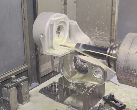
Where complex organic shapes or weight-optimized structures are required, 5-axis machining is often chosen, but the geometry should still be designed with reachable tool angles and stable clamping surfaces.
Tolerances and Fits for Robotic Components
Robotics applications often require tighter tolerances than general machinery, especially in kinematic chains and precision alignment parts. Typical guiding values (actual values must be chosen based on specific design requirements):
For general structural features and non-critical holes, tolerances around ±0.05 mm to ±0.10 mm are common. For bearing bores and shaft fits, tolerances often range from ±0.005 mm to ±0.02 mm. For dowel pin locations used for repeatable positioning, positional tolerance may be within 0.01 mm to 0.05 mm relative to reference datums. For parallelism and perpendicularity between mounting faces of major axes, typical geometric tolerances are 0.02 mm to 0.05 mm over the length of the interface.
Choosing unnecessarily tight tolerances increases machining and inspection time. A systematic tolerance stack-up analysis should be performed only on those features that directly influence position, orientation, or backlash of the robot.
Threading, Fastening, and Assembly Interfaces
Robotic assemblies are frequently disassembled for maintenance, upgrades, and tuning. Threaded holes and interfaces must be designed for both strength and serviceability. Guidelines include using standard metric threads (for example M4, M5, M6, M8, M10) with adequate engagement length, typically 1.5 times the nominal diameter in aluminum and 1.0 to 1.2 times the nominal diameter in steel, and using through-holes where possible to simplify chip evacuation and avoid blind tap breakage.
Interfaces between modules often use locating dowel pins combined with clearance bolt holes. Dowel pin fits are typically tight (for example h6 in bores) to achieve consistent repositioning. When mating aluminum and steel or stainless steel components, galvanic corrosion and different thermal expansion coefficients should be considered, especially in environments with temperature changes or moisture.
CNC Machining Processes Used in Robotics
Multiple CNC processes are combined to produce robotic parts efficiently, depending on geometry, quantity, and material.
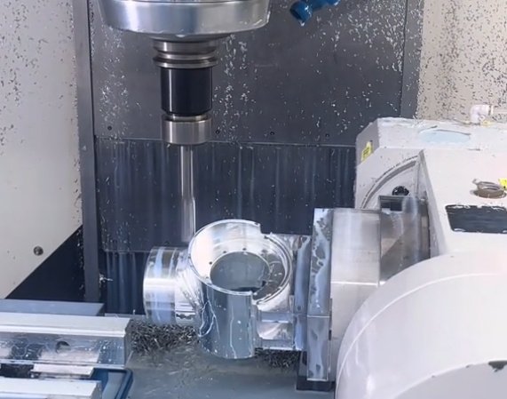
CNC Milling
CNC milling is used for robot arms, base plates, gearbox housings, gripper jaws, and many structural brackets. 3-axis milling covers prismatic parts with features accessible from a few directions, such as plates, blocks, ribs, and pockets. 4-axis milling adds a rotary axis, enabling machining of multiple sides in a single setup, useful for long arms, cylindrical housings, and components with radial hole patterns. 5-axis milling allows tool angles to be controlled in two rotational axes, enabling free-form surfaces, complex undercuts, and optimized lightweight structures in high-performance manipulators or autonomous systems.
CNC Turning
CNC turning is essential for rotational parts such as shafts, rollers, couplings, pulleys, and certain types of end-effector components. Typical operations include outer diameter turning and facing, boring of internal diameters for bearings and bushings, grooving for retaining rings and seals, and threading for nuts, shafts, and adapters. For high concentricity between shaft sections or between inner and outer diameters, parts may be turned between centers or machined in a single clamping operation.
Secondary Operations and Finishing Steps
After primary milling and turning, robotic parts frequently require secondary operations:
Drilling and tapping for fasteners and sensors, reaming for precise dowel and bearing fits, broaching for keyways, deburring for safe handling and reliable assembly, and surface treatments such as anodizing, plating, and painting. When robotic assemblies must move smoothly with low friction, additional operations such as grinding, lapping, or honing can be used on sliding or rotating surfaces, depending on the precision level and load conditions.
Material Selection for CNC-Machined Robotic Parts
Material choice affects mass, stiffness, durability, cost, and compatibility with actuators and sensors. The main classes are metals, engineering plastics, and occasionally composites with CNC-machined inserts.
| Material | Typical Use in Robotics | Key Properties for Design |
|---|---|---|
| Aluminum 6061-T6 | Frames, brackets, end-effector bodies | Good strength-to-weight, easy machining, suitable for anodizing |
| Aluminum 7075-T6 | High-load arms, compact actuators | Higher strength and stiffness than 6061, slightly more expensive, good fatigue properties |
| Steel (e.g., 1018, 1045) | Shafts, gears, structural joints | High strength, high stiffness, heavier, good wear resistance |
| Stainless Steel (e.g., 304, 316) | Food, medical, and corrosive environments | Corrosion resistance, good strength, lower machinability than standard steels |
| Tool Steel (e.g., D2, O1) | Wear surfaces, precision pins, guiding elements | High hardness after heat treatment, wear resistance, suitable for repeated load cycles |
| Titanium (e.g., Ti-6Al-4V) | Weight-critical, high-load parts | Very high strength-to-weight, corrosion resistance, more difficult and costly to machine |
| Delrin (POM) | Bushings, gears, low-friction components | Low friction, good dimensional stability, lightweight, easy to machine |
| Nylon (often with fillers) | Wear pads, cable guides, protective components | Tough, good impact resistance, moisture absorption must be considered |
| PEEK | High-temperature or chemically exposed parts | High temperature capability, chemical resistance, high cost |
Metals for Structural and Precision Parts
Aluminum alloys are widely used in robotic frames, arms, and tooling plates due to their high stiffness-to-weight ratio and favorable machinability. Aluminum 6061-T6 is common for general purpose structures, while 7075-T6 is chosen when higher strength and fatigue resistance are required in compact geometries.
Carbon steels and alloy steels are favored for shafts, gears, and other components subject to high stresses, impact, or wear. These materials can be heat-treated for strength and hardness, which is important in robot joints, drive trains, and load-bearing interfaces. Stainless steels are selected where corrosion resistance is important, such as in food-processing robots, outdoor robots, and medical applications.
Titanium alloys may be used for high-performance robots where weight reduction is critical while maintaining strength, for example in aerospace-related robotic systems or mobile platforms with strict mass budgets.
Plastics and Hybrid Components
Engineering plastics complement metal structures in certain robotic functions. Delrin is often used for low-friction guides, gear components under moderate loads, and precision spacers. Nylon and UHMW-PE are used for wear strips, cable chain guides, and noise reduction elements. PEEK and other high-performance polymers appear in environments with elevated temperature or chemical exposure, including some laboratory automation and process robotics.
Hybrid metal-plastic designs are common, such as aluminum frames with plastic bushings and covers, or steel shafts with plastic gears in low-noise applications. Using plastics in appropriate locations can reduce inertia and protect delicate sensors or wiring harnesses.
Surface Finishes and Treatments for Robotic Parts
Surface finish influences wear, friction, corrosion resistance, and cleanliness. The correct finish is chosen based on the mechanical function and environment of the robot.
Machined Surface Roughness
Typical as-milled surface roughness may range from Ra 1.6 µm to 3.2 µm depending on cutting parameters and tooling. For sliding surfaces, sealing surfaces, and bearing seats, better surface finishes such as Ra 0.4 µm to 1.6 µm are often applied through fine milling, grinding, or other finishing processes. Rougher surfaces may be acceptable for non-critical structural areas.
Protective and Functional Coatings
Common treatments for robotic components include anodizing for aluminum, which provides corrosion resistance, electrical insulation for some types, and an improved surface hardness. Clear or colored anodizing can also be used for visual identification of modules. Zinc plating and other galvanic coatings on steel prevent corrosion, especially on fasteners and exposed structural parts. Electroless nickel plating offers uniform coverage, increased hardness, and improved wear resistance and is used for precision components or parts in contact with lubricants where cleanliness is required.
For stainless steel, passivation removes free iron from the surface and improves corrosion resistance. In applications that require minimal particulate generation or contamination, such as cleanroom robotics, surfaces are often polished or treated to reduce particle shedding and ease cleaning.
Accuracy, Repeatability, and Quality Control
CNC machining can achieve high levels of accuracy, which must be maintained through suitable design and quality control methods to meet robotic performance requirements.
Dimensional Accuracy and Geometric Precision
Modern CNC machines can routinely achieve dimensional tolerances of ±0.01 mm or better on stable parts, assuming appropriate tooling, fixturing, and process control. However, achievable accuracy depends on part size, material, and thermal conditions. For long robot arms or base structures, temperature-induced expansion may contribute more to total error than the machine tools themselves, so reference temperatures and inspection conditions must be controlled.
Geometric tolerances such as flatness, parallelism, and perpendicularity are critical for axis alignment and linear guide seating. Geometrically accurate machined surfaces reduce the need for shimming and manual alignment during assembly, which directly affects repeatability and calibration stability of robotic systems.
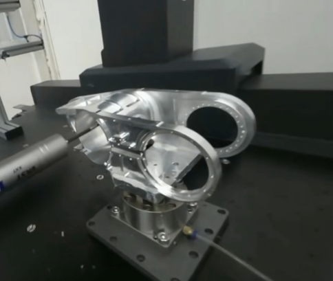
Inspection Methods for Robotic Components
Inspection strategies are chosen based on tolerance requirements and production volumes. Common methods include coordinate measuring machines for high-accuracy dimensional and geometric checking of critical components like joint housings, bearing bores, and metrology-related parts. Digital calipers, micrometers, bore gauges, and height gauges are used for routine dimensions and process checks on structural components.
Optical measurement systems and laser scanners may be used for complex free-form surfaces or large assemblies where contact measurement is inefficient. When robotic systems require high positional accuracy, the mounting surfaces and reference holes are often fully documented with measurement reports to support later calibration and field maintenance.
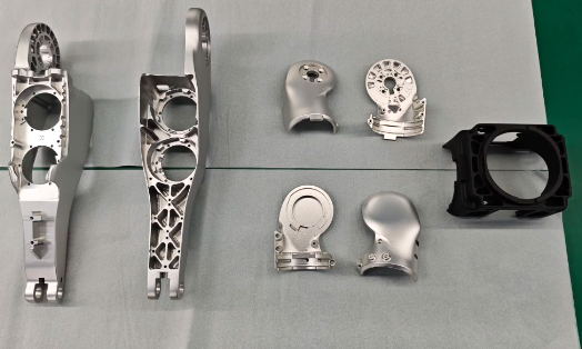
Common CNC-Machined Components in Robotics
Robotic systems consist of subsystems, many of which rely on CNC-machined parts for function and reliability.
Robot Bases and Frames
Robot bases, pedestals, and main frames provide the reference geometry for all axes. They typically use thick aluminum or steel plates, box sections, and precision-machined mounting faces for linear rails and rotary bearings. Slots or holes for cable routing and pneumatic lines are planned to avoid interference with motion and to simplify assembly.
Joints, Housings, and Actuator Mounts
Each joint in an articulated robot often includes a CNC-machined housing that supports bearings, seals, and gear trains, as well as features for motor mounting and feedback devices. Precise alignment between motor shafts, gear sets, and output arms is essential to minimize backlash and eccentricity. Machined reference surfaces inside the housing provide stable locations for bearings and seals, helping maintain internal clearances under load and temperature variation.
End-Effectors and Tooling
End-effectors are highly varied but typically contain a significant amount of CNC machining. Gripper jaws are often machined from aluminum or steel, with pockets or contours matched to the shape of the workpiece. Tool plates and quick-change adapters use precision bolt hole patterns and dowel pin arrangements to ensure consistent tool positioning. In welding, cutting, or inspection robots, dedicated fixtures and tool holders are CNC machined to keep process tools in precise relation to the robot flange.
Sensor and Camera Mounts
Sensor brackets and camera housings must maintain stable orientation, often under vibration and dynamic loading. These parts are usually machined from aluminum, with features for cable management, shielding, and alignment. For vision systems, the relative position of camera, lens, and sometimes illumination components is controlled by precise machined interfaces. Tolerances and repeatable mounting schemes reduce recalibration time when systems are serviced or reconfigured.
Cost Structure of CNC Machining for Robotics
Total cost of CNC-machined robotic parts depends on setup, cycle time, materials, volume, and quality requirements. Understanding the cost structure helps engineers optimize designs and budgets.
| Cost Element | Description | Design Influence |
|---|---|---|
| Setup and Programming | Time to prepare CAM programs, tool paths, fixturing, and machine setup | Simpler geometries and fewer setups reduce non-recurring engineering and setup costs |
| Machine Cycle Time | Actual machining time including cutting, tool changes, and part handling | Reduced material removal volume and fewer complex features decrease cycle time |
| Material Cost | Raw stock cost and yield from the chosen stock size | Compact designs and efficient stock sizes minimize waste and material expense |
| Tooling and Consumables | Cutting tools, inserts, coolants, and wear-related consumables | Material hardness, geometry complexity, and required surface finish affect tooling costs |
| Inspection and Quality Control | Measurement, documentation, and possible certification activities | Tight tolerances and extensive measurement requirements increase quality cost |
| Post-Processing | Surface treatments, heat treatment, deburring, and finishing | Choice of finishes, coatings, and treatments affects both direct costs and lead time |
Setup, Programming, and Non-Recurring Costs
For new robotic components, engineers must account for setup and programming time. This includes CAM programming, fixture design, initial trials, and first article inspection. For small prototype quantities, these non-recurring costs may represent a significant portion of the total, whereas in higher-volume production the cost per part decreases substantially as setup time is amortized.
Design choices that ease fixturing and reduce the number of required setups directly lower non-recurring cost. For example, designing parts that can be machined from two primary orientations instead of four or more simplifies fixtures and reduces operator time.
Volume, Complexity, and Unit Price
Unit price is influenced by both batch size and part complexity. A simple end-effector bracket may require only basic 3-axis milling with a short cycle time, producing a relatively low unit cost even in moderate volumes. In contrast, a complex multi-axis housing with extensive internal features, tight tolerances, and several finishing operations will have higher unit cost.
For robotics projects that evolve through multiple prototypes, engineers can reduce cost by reusing key interfaces and design patterns so that existing fixtures and programs can be leveraged across iterations. This approach can be effective in modular robotic platforms where only certain sub-components are changed between generations.
Material and Treatment Costs
Material selection has a direct influence on both material cost and machining time. Standard aluminum alloys are generally more economical than titanium, tool steels, or high-performance plastics. Thicker sections and high material removal ratios increase cycle time due to heavier cutting. Surface treatments and coatings add both direct processing cost and handling time. For example, hard anodizing or electroless nickel plating involve external processing steps with additional lead time and quality control procedures.
Practical Considerations and Common Issues in Robotic CNC Parts
When robotic components move at high speeds, carry loads, or operate continuously, small design or manufacturing issues can lead to misalignment, wear, or unexpected downtime.
Alignment and Stack-Up Effects
In multi-axis robots, small deviations in each component can accumulate along the kinematic chain. Even when individual parts meet their tolerances, the combined error may affect repeatability or reach accuracy. Designers should use datums and tolerances that reflect the actual assembly sequence, and wherever possible, use locating features such as dowel pins or precision shoulders instead of relying solely on bolt clearances.
Weight, Inertia, and Motor Sizing
Excessive mass in arms and end-effectors increases motor torque requirements, energy consumption, and structural loads. The machining design stage is an important opportunity to reduce mass by using pockets, ribs, and optimized cross-sections without compromising stiffness. An efficient design may allow the use of smaller motors and gearboxes, which in turn reduce total cost and improve dynamic performance.
Serviceability and Replacement Parts
Robotic systems often need scheduled maintenance or replacement of wear components. Designs that allow easy access to fasteners, clear disassembly paths, and interchangeable modules reduce downtime. From a machining perspective, using standard stock sizes, standard fastener patterns, and consistent interface geometries helps ensure that spares can be produced quickly and reliably, even if produced by different machine shops.
Workflow: From CAD Model to Finished Robotic Part
The path from concept to usable CNC-machined component for robotics can be defined in structured steps that support both quality and cost control.
Design and Engineering Validation
Engineers begin with CAD models and perform structural and kinematic analysis to confirm that the design meets stiffness, strength, and range-of-motion requirements. At this stage, features that are difficult to machine or inspect can be simplified, and tolerances can be adjusted to match the manufacturing capability of selected suppliers.
DFM Review, Quoting, and Supplier Selection
Once the design is stable, a design-for-manufacturing review addresses tool access, fixture points, and realistic tolerances. Drawings and models are sent to machine shops for quoting. Supplier selection should consider technical capability, experience with robotic parts, equipment (3-axis, 5-axis, turning centers, inspection tools), and lead times, not only price.
Prototyping, Testing, and Iteration
Prototype parts are produced and inspected, then installed into test robotic assemblies. Mechanical behavior, fit, and interaction with sensors and actuators are verified. Based on feedback, engineers may adjust dimensions, clearances, or materials. After design freeze, the same CNC programs and process plans may be adapted for higher-volume production with refined cycle time optimization.
