
Rapid prototyping transforms digital designs into physical parts in short lead times, enabling fast design validation, functional testing, and low-volume production. Understanding available materials, machining processes, tolerances, and cost drivers is essential to select the right approach for each development stage and budget.
Core Purpose of Rapid Prototypes
Rapid prototypes support product development by providing physical representations of a design before committing to full-scale manufacturing. They can range from basic visual models to fully functional assemblies used for performance tests or regulatory submissions.
Typical objectives include:
- Evaluating fit, form, and ergonomics of components and assemblies
- Testing functional performance under mechanical, thermal, or chemical loads
- Verifying manufacturability and assembly processes
- Supporting stakeholder communication, marketing, and early customer feedback
Choosing the appropriate material and machining or additive process determines the accuracy, durability, and total cost of a prototype. In many cases, several iterations are required, each with different technical requirements.
Material Categories for Rapid Prototyping
Material selection is a primary factor in performance and cost. Materials for rapid prototyping fall into several broad categories: plastics, metals, elastomers, and hybrid or composite materials. Each category offers specific mechanical properties, machining characteristics, and cost profiles.
Plastics for Rapid Prototypes
Plastics are widely used due to low material cost, ease of machining, and compatibility with most 3D printing and subtractive processes. They are suitable for housings, enclosures, clips, gears, and many structural or semi-structural components.
Common engineering plastics:
- ABS: Good impact resistance, easy to machine and 3D print; suitable for enclosures and structural prototypes.
- PC (Polycarbonate): High impact strength and heat resistance; used for clear or tough functional parts.
- PA (Nylon): High toughness and wear resistance; suitable for gears, bearings, and hinges.
- POM (Acetal/Delrin): Low friction, high stiffness; used for sliding components and precision parts.
- PEEK: High temperature, chemical resistance, and strength; used for demanding functional prototypes.
Key plastic properties relevant to rapid prototypes:
Mechanical:
- Tensile strength: approx. 30–60 MPa for standard engineering plastics, up to 90–100 MPa for high-performance plastics like PEEK.
- Flexural modulus: 1–3 GPa for many common grades, influencing stiffness.
Thermal:
- Heat deflection temperature (HDT): around 80–110 °C for ABS/PC, higher for high-performance plastics.
Other considerations include moisture absorption (important for nylons), UV stability, and chemical resistance.
Metals for Rapid Prototypes
Metal prototypes are used where mechanical strength, thermal stability, or electrical conductivity are required. They can be produced via CNC machining, sheet metal forming, metal 3D printing, or casting.
Typical metals:
- Aluminum alloys (e.g., 6061, 7075): Low density, good machinability, suitable for structural parts and housings.
- Stainless steels (e.g., 304, 316, 17-4PH): Corrosion resistant, higher strength, used for mechanical and medical prototypes.
- Carbon steels (e.g., 1018, 4140): Higher strength and hardness potential, used for wear components and tooling.
- Titanium alloys (e.g., Ti-6Al-4V): High strength-to-weight ratio, excellent corrosion resistance, used in aerospace and medical prototypes.
Typical property ranges:
- Tensile strength: 150–600 MPa for many aluminum and stainless steels; higher for hardened or high-strength alloys.
- Yield strength: 75–450 MPa depending on alloy and heat treatment.
- Thermal conductivity: high for aluminum (approx. 150–200 W/m·K), lower for stainless steels.
Metal choice directly affects machining time, tool wear, and achievable surface finish, all of which have cost implications.
Elastomers and Flexible Materials
Elastomeric prototypes are used for seals, gaskets, vibration dampers, wearables, overmolded grips, and flexible connectors.
Common materials:
- Silicone rubber: Wide temperature range, excellent flexibility, often used for medical and consumer products.
- TPU (Thermoplastic polyurethane): Flexible, abrasion-resistant; suitable for flexible housings and impact protection.
- EPDM and NBR: Used for seals and gaskets requiring specific chemical or weather resistance.
Relevant parameters include Shore hardness (e.g., Shore A 30–90), compression set, and operating temperature range. Production routes include casting in silicone molds, 3D printing of flexible resins or filaments, and CNC machining of softer thermoplastic elastomers when geometrically feasible.
Hybrid and Composite Materials
Hybrid materials combine two or more constituents to achieve specific properties, such as high stiffness and low weight, improved wear resistance, or tailored thermal characteristics.
Examples:
- Fiber-reinforced polymers (e.g., carbon fiber–reinforced nylon): High stiffness and strength with low density.
- Metal-polymer hybrids: Overmolded structures for improved ergonomics and vibration damping.
These materials may require specialized machining strategies or printing processes, and can impact both lead time and cost due to tooling, consumables, and finishing requirements.
Machining and Manufacturing Processes for Rapid Prototypes
Rapid prototypes can be produced by subtractive, additive, or formative processes. Selection depends on geometry complexity, tolerance requirements, mechanical performance, surface finish, and cost constraints.
Subtractive Machining Processes
Subtractive methods remove material from a solid block or sheet. CNC machining is the most common, followed by manual machining for simple parts and very low quantities.
Key processes:
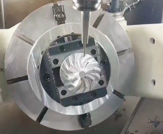
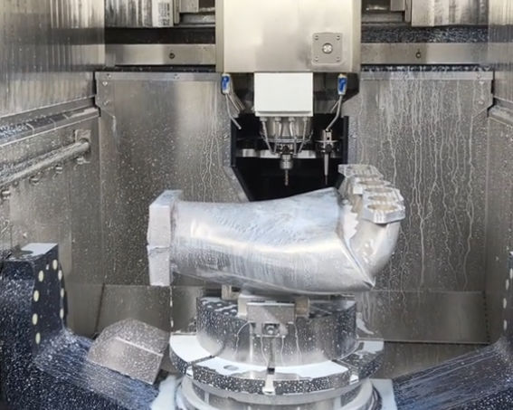
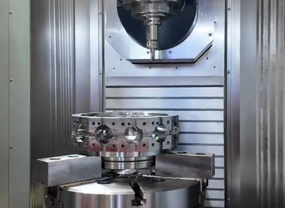
- CNC milling: Suitable for prismatic parts, pockets, slots, and freeform surfaces using multi-axis machines (3-axis, 4-axis, 5-axis).
- CNC turning: Efficient for rotationally symmetric parts, shafts, bushings, and threaded components.
- Wire EDM and sinker EDM: Used for fine details, hard materials, and sharp internal corners.
Typical capabilities for CNC-machined prototypes:
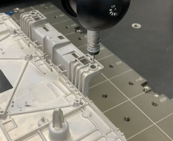
- Tolerances: ±0.01–0.05 mm for many features, tighter tolerances possible with appropriate setup.
- Surface roughness: Ra 0.8–3.2 μm directly from machining, improved by polishing or grinding.
- Lead time: Often 1–7 days depending on complexity and queue.
Subtractive methods are preferred when the prototype material must match production material, or when fine tolerances and stable mechanical performance are required.
Additive Manufacturing (3D Printing)
Additive processes build parts layer by layer from digital models. They are highly effective for complex geometries, internal channels, lattice structures, and low-volume production without dedicated tooling.
Representative processes:
- Fused Deposition Modeling (FDM/FFF): Thermoplastic filament extrusion; suitable for concept models and some functional parts.
- Stereolithography (SLA): Photopolymer resin curing; delivers fine details and smooth surfaces, often used for visual and fit prototypes.
- Selective Laser Sintering (SLS): Powder bed fusion of plastics; produces strong, nylon-based functional parts.
- Direct Metal Laser Sintering (DMLS) / Selective Laser Melting (SLM): Powder bed fusion for metals; used for complex metal components.
General performance characteristics:
- Feature resolution: often 0.05–0.15 mm for fine polymer processes, larger for FDM; metals typically 0.03–0.1 mm layer height.
- Tolerances: around ±0.1–0.3 mm depending on process, part size, and post-processing.
- Surface finish: process-dependent; many 3D printed parts require sanding, machining, or coating for final appearance.
3D printing is efficient for design validation, rapid iterations, and complex geometries that would be expensive by machining alone. However, material properties and dimensional accuracy may differ from final production methods, which must be considered in functional testing.
Formative and Hybrid Processes
Formative processes rely on molds or dies to shape material. For rapid prototyping, soft tooling and bridge tooling are often used to balance speed and part performance.
Representative approaches:
- Vacuum casting using silicone molds: Typically used to replicate polyurethane or other castable resins from a master pattern. Common for short runs of 5–50 pieces.
- Low-volume injection molding with aluminum tooling: Enables near-production parts in standard thermoplastics with reduced tooling cost and lead time.
- Sheet metal prototyping: Bending, laser cutting, punching, and welding for enclosures, brackets, and panels.
These methods are relevant when more than a handful of parts are needed or when the parts must closely simulate production materials, manufacturing behavior, and appearance while maintaining relatively short lead times.
Dimensional Accuracy, Tolerances, and Surface Finish
Tolerance Capabilities by Process
Dimensional performance is a critical selection criterion for machining processes and materials. Tolerances and surface finishes directly affect assembly fit, functional performance, and post-processing requirements.
The following table summarizes typical tolerance ranges achievable in rapid prototyping with commonly used processes, assuming proper design and process control. Actual values depend on part size, geometry, and material.
| Process | Material Types | Typical Tight Tolerance Range | Notes |
|---|---|---|---|
| CNC machining (milling/turning) | Metals, engineering plastics | ±0.01–0.05 mm | Best suited for precision interfaces, press fits, and alignment features. |
| SLA 3D printing | Photopolymer resins | ±0.05–0.15 mm | High detail; accuracy affected by part size and orientation. |
| SLS 3D printing | Nylon and similar powders | ±0.1–0.3 mm | Good for functional parts; surface is slightly grainy. |
| FDM 3D printing | Thermoplastic filaments | ±0.15–0.5 mm | Accuracy influenced by nozzle size, shrinkage, and warpage. |
| DMLS/SLM metal printing | Steel, aluminum, titanium | ±0.05–0.2 mm | Often followed by machining of critical surfaces. |
| Vacuum casting | Cast resins | ±0.1–0.3 mm | Depends on master accuracy and mold handling. |
For assemblies requiring consistent fit across multiple batches, it is common to combine 3D printing or casting for general geometry with CNC machining of critical interfaces.
Surface Roughness and Post-Processing
Surface finish affects appearance, friction behavior, sealing performance, and sometimes mechanical strength. Roughness values and finishing options vary by process.
Typical surface characteristics:
- CNC machining: Ra ≈ 0.8–3.2 μm, improved via grinding, polishing, or bead blasting.
- SLA: Smooth surfaces comparable to fine injection-molded parts after light finishing.
- SLS and FDM: Layered, sometimes visibly stepped surfaces; may require sanding, tumbling, or coating.
- Metal 3D printing: Rough surfaces due to powder and melt pool characteristics; often require machining or blasting.
Post-processing options:
- Mechanical: sanding, tumbling, shot peening, bead blasting.
- Chemical: vapor smoothing for some plastics.
- Coatings: painting, powder coating, anodizing, plating for metals.
Post-processing contributes to total cost and lead time and must be factored into planning for prototypes requiring cosmetic-grade surfaces or sealed interfaces.
Cost Structure of Rapid Prototyping
Prototype cost is influenced by material usage, machine time, labor for setup and finishing, and any tooling or specialized operations. Understanding the main cost drivers helps in selecting cost-effective configurations while meeting technical requirements.
Cost Components by Common Process
The following table provides a structured view of major cost components for typical rapid prototyping processes. The relative contributions will vary by supplier, region, and order volume.
| Process | Main Cost Components | Typical Cost Sensitivity | Notes |
|---|---|---|---|
| CNC machining | Material stock, machine time, programming, tooling, finishing | Highly sensitive to complexity and setup; moderate sensitivity to quantity | Simple geometries in common materials remain economical at low volumes. |
| FDM 3D printing | Material, machine time, support removal | Sensitive to build time and part volume; low tooling cost | Cost-effective for bulky but low-precision prototypes. |
| SLA/SLS 3D printing | Powder/resin, machine time, depowdering, post-curing | Sensitive to volume and orientation; low incremental cost for multiple parts in one build | Batching multiple parts improves cost per unit. |
| DMLS/SLM metal printing | Metal powder, machine time, support removal, heat treatment | Highly sensitive to build height and density | Generally higher cost; justified by complex metal geometries. |
| Vacuum casting | Master model, silicone molds, casting resin, labor | Upfront master and mold costs; per-part cost decreases with quantity | Best suited for batches of approximately 5–50 parts. |
| Low-volume injection molding | Tooling, molding cycles, resin, finishing | High initial tooling cost; low marginal cost per part | Becomes economical as quantities increase beyond prototype scale. |
Factors Influencing Prototype Cost
Key factors that affect total cost include:
- Geometry complexity: undercuts, thin walls, deep cavities, and tight internal features increase setup time and tooling or support requirements.
- Tolerance and quality constraints: tighter tolerances, higher surface quality, and additional inspections add machining and finishing time.
- Material choice: high-performance polymers, specialty alloys, and certified materials are costlier than commodity plastics and standard metals.
- Quantity: higher quantities may shift the optimal process from 3D printing to casting or low-volume molding.
- Lead time: accelerated delivery often requires prioritization, extended machine hours, or parallel processing, which add cost.
For budgeting, it is common to obtain iterative quotations as the design evolves, especially when changing processes or materials between early concept and pre-production prototypes.
Design and Material Selection for Cost-Effective Rapid Prototypes
Efficient prototyping requires alignment between design intent, material behavior, and the chosen process. Early optimization can reduce iterations, save cost, and shorten development cycles.
Aligning Prototype Requirements with Material Properties
Materials should be selected based on the specific purpose of the prototype rather than solely on the intended production material. For example:
- Ergonomic and appearance models may be produced in low-cost plastics with painting or texturing to simulate final materials.
- Functional prototypes for structural testing benefit from materials with similar modulus, strength, and thermal behavior to the production grade.
- Prototypes used in environmental or chemical testing must match or closely approximate the actual production material.
Important material parameters to consider include tensile strength, modulus, elongation at break, impact resistance, coefficient of thermal expansion, temperature resistance, and, for some applications, dielectric properties or thermal conductivity.
Design Guidelines for Machining-Based Prototypes
To ensure manufacturability and cost efficiency when using CNC machining or other subtractive processes, design should consider:
- Minimum wall thickness: adequate thickness (often ≥1–1.5 mm for metals and ≥1.5–2 mm for plastics) to avoid deflection or damage during machining.
- Internal corner radii: using radii compatible with standard tool diameters minimizes custom tooling and machining time.
- Hole and thread specifications: standard metric or imperial sizes simplify tooling and reduce setup changes.
- Fixturing and accessibility: avoid deep, narrow pockets and hidden surfaces that require special fixtures or multi-step setups when possible.
Implementing these guidelines early reduces the need for design modifications purely for manufacturability and helps keep prototype costs predictable.
Design Guidelines for Additive Prototypes
For 3D printed parts, design considerations differ from machining:
- Support structures: overhangs, bridges, and complex internal features may need support; reducing these features saves post-processing time.
- Anisotropy: mechanical properties can vary by build direction; critical load-bearing features should be oriented accordingly.
- Minimum feature size: features smaller than the process resolution may not print reliably; consult the process specification for minimum wall, hole, and gap sizes.
- Assembly integration: 3D printing allows monolithic assemblies with hinges or joints, reducing component count and assembly time but requiring careful clearance design.
Combining additive and subtractive approaches is common: 3D printing is used for complex shapes, followed by machining of precision interfaces, threads, or sealing surfaces.
Typical Use Cases and Process Selection Examples
Prototyping needs can be broadly categorized, and suitable process/material combinations can be determined by matching performance requirements and budget constraints.
Concept and Visual Models
Concept models are primarily used to communicate design intent, basic size, and appearance. Requirements are usually modest in terms of mechanical performance and accuracy but may involve visual realism.
Suitable approaches:
- FDM or SLA printing with cosmetic finishing for realistic visual demonstrators.
- CNC machining of plastics for smooth surfaces suitable for painting and texture simulation.
Materials are chosen for ease of finishing and cost, with moderate tolerance requirements. Costs are driven by size, surface quality, and finishing rather than mechanical performance.
Functional Prototypes and Testing Parts
Functional prototypes are subjected to mechanical loads, thermal cycling, or environmental exposure. They should approximate production material behavior to generate meaningful test results.
Typical combinations:
- CNC-machined aluminum or steel for structural mechanical components.
- SLS nylon parts for durable plastic assemblies with integral hinges or internal features.
- Metal 3D printing followed by machining for complex high-strength parts operating in demanding environments.
In this category, tolerances, fatigue performance, and material stability become critical. Costs are influenced by required strength, precision, and number of test samples.
Low-Volume and Bridge Production
When volumes extend beyond a few prototypes but do not yet justify full-scale production tooling, low-volume solutions are used to bridge the gap.
Suitable options:
- Vacuum casting for small batches of plastic parts with near-production appearance.
- Aluminum tooling for injection molding of tens to low thousands of parts.
- Sheet metal fabrication for enclosures, brackets, and frames in small series.
These methods enable market testing, pilot runs, and pre-production build events while maintaining controlled cost and lead time. The main cost contribution shifts from individual part complexity to tooling effort and repeatability.
Practical Cost Optimization Strategies
Cost efficiency in rapid prototyping is achieved by coordinated choices in design, process, and order planning. Several practical measures can significantly influence project budgets without compromising core objectives.
Process Selection and Mixed-Method Strategies
Not all parts in an assembly require the same level of accuracy, material, or process sophistication. A mixed-method strategy may include:
- Using 3D printed dummy components for non-critical parts and CNC machining for critical interfaces.
- Combining vacuum casting for cosmetic outer shells with machined metal inserts for load-bearing structures.
- Producing preliminary versions via printing for design refinement, followed by machined or molded versions for performance validation.
This approach keeps early iteration costs low while ensuring that final evaluation prototypes closely represent the production intent.
Standardization and Consolidation
Standardization of features and consolidation of orders can reduce prototyping costs.
Key measures:
- Using standard fasteners, hole sizes, and thread types to avoid special tooling.
- Designing parts that share material and process requirements, enabling batching in a single machining or printing job.
- Minimizing the number of distinct materials used in early prototypes to simplify procurement and setup.
These measures reduce setup time, material changeovers, and handling complexity, leading to more predictable pricing and shorter lead times.
Summary
Rapid prototyping relies on a combination of materials, machining methods, and additive processes to transform digital concepts into physical parts quickly and economically. Plastics, metals, elastomers, and composites each serve specific roles, from visual models to high-performance functional parts. Subtractive CNC machining offers high precision, while additive manufacturing provides freedom of geometry and minimal tooling. Formative approaches such as vacuum casting and low-volume molding bridge the gap between prototyping and production.
Cost is determined by material choice, geometric complexity, required tolerances and surface finish, quantity, and lead time. Thoughtful design for manufacturability, appropriate process selection, and strategic use of mixed approaches can reduce expenses and accelerate development while maintaining technical integrity.
FAQ
What is a rapid prototype?
A rapid prototype is a quickly produced physical model of a part or product used for design validation, functional testing, and visual evaluation before mass production.
What machining methods are used for rapid prototyping?
Rapid prototyping can be done using CNC machining, 3D printing, vacuum casting, and sheet metal fabrication. CNC machining is ideal for high-precision functional prototypes, while 3D printing is best for fast visual models.
Which is better for rapid prototyping: CNC machining or 3D printing?
CNC machining is better for high-precision, strong, and functional prototypes, while 3D printing is more cost-effective and faster for complex shapes and visual models. The best choice depends on your project goals.
How can I reduce the cost of rapid prototyping?
You can reduce rapid prototyping costs by simplifying part geometry, choosing cost-effective materials, loosening tolerances, reducing surface finish requirements, and ordering small quantities for early-stage testing.
