
Precision shafts are critical components for transmitting torque, positioning loads, and guiding linear or rotary motion in mechanical and mechatronic systems. Their dimensional accuracy, surface finish, straightness, and material properties directly influence system performance, repeatability, noise, and service life. This article systematically explains precision shaft applications, design parameters, material choices, machining considerations, and integration with mating components for industrial, automation, and equipment-building use cases.
Fundamental Roles of Precision Shafts
Precision shafts serve multiple functions in mechanical assemblies and automation equipment. Their design and specification depend on the dominant role in the system.
Rotary Power Transmission
In rotary systems, shafts transmit torque between power sources and driven components. Examples include:
- Motor to gearbox input shafts
- Gearbox output shafts to couplings, pulleys, or sprockets
- Spindle shafts in machine tools and grinders
- Drive shafts in pumps, compressors, and blowers
Key requirements in such applications typically include torsional stiffness, adequate fatigue strength, controlled runout, and suitable fit with bearings and transmission elements (gears, pulleys, couplings).
Linear Guidance and Support
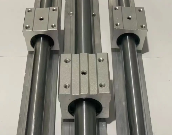
In linear motion systems, precision shafts are used as guide rails or support rods for bushings, linear bearings, or carriages. They provide a straight, smooth, and rigid path for translational movement. Typical uses include:
- Linear stages and actuators
- 3D printers and pick-and-place machines
- Packaging machines and conveyors
- Inspection equipment and optical positioning systems
For these applications, straightness, surface hardness, roundness, and low surface roughness are emphasized. Deflection under load must be controlled to maintain alignment and positioning accuracy.
Alignment, Location, and Support Functions
Precision shafts are also used as locating pins, alignment shafts, or support posts to ensure positional accuracy between components. They can constrain degrees of freedom and maintain consistent relationships between subassemblies. Typical roles include:
- Locating shafts between machine frames and plates
- Guide shafts for sliding or swiveling fixtures
- Support posts for tooling nests or jigs
Dimensional tolerances, perpendicularity, and fit with mating bores are important in these use cases to ensure repeatable assembly and easy service.
Types of Precision Shafts and Configurations
Precision shafts are available in multiple geometries and construction methods, each optimized for specific application requirements.
Solid vs. Hollow Shafts
Solid shafts are the most common form, providing high torsional stiffness and simple manufacturing. Hollow shafts are used when weight reduction, improved dynamic behavior, or internal routing is needed. Hollow designs can offer a favorable strength-to-weight ratio and are used in high-speed spindles, robotics, and applications requiring cable or fluid passage through the shaft center.
Ground, Turned, and Polished Shafts
Precision shafts differ by how their surface and dimensions are finished:
Ground shafts are processed using centerless or cylindrical grinding to achieve tight tolerances on diameter, roundness, and surface finish. These are commonly used as linear bearing shafts, precision spindle journals, and alignment shafts.
Turned and polished shafts are produced by turning followed by polishing or burnishing. They provide good but typically less precise surface finish and tolerances compared to ground shafts and are widely used for general power transmission and structural roles.
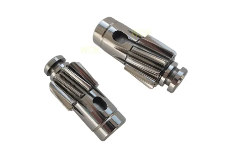
Keyed, Splined, and Threaded Shafts
To transmit torque and provide axial retention, shafts can incorporate different end or mid-section features:
Keyed shafts have keyways that mate with keys in hubs, pulleys, or gears, providing positive torque transmission. Splined shafts use multiple teeth for torque transfer and can allow axial sliding in certain spline forms. Threaded ends enable mechanical fastening of nuts, collars, and other components for axial positioning and preload.
Linear Shaft Variants
For linear motion, several shaft variants exist:
Shafts with or without supports: Some designs use fully supported shafts mounted on aluminum rails, while others are unsupported and rely on shaft stiffness alone. Shaft end machining can be provided to integrate couplings, encoders, or mounting hardware.
Corrosion-resistant shafts: Stainless steel or coated shafts are used in washdown, food, and pharmaceutical environments. Hardened and chromed shafts increase wear resistance for heavy-duty linear bearings.
Key Design and Selection Parameters
Accurate specification of precision shafts requires careful consideration of dimensional, mechanical, and geometric parameters.
Diameter, Length, and Slenderness
Shaft diameter and length determine bending stiffness, torsional stiffness, and critical speed. The length-to-diameter ratio (slenderness) is a useful indicator for deflection and vibration sensitivity. Long, slender shafts are more prone to bending and dynamic instability and may require supports, intermediate bearings, or diameter increases.
Tolerances and Fits
Shaft diameter tolerances must be compatible with mating components such as bearings, hubs, and bushings. Common tolerance systems use ISO fits, where shaft and bore tolerances are defined to achieve clearance, transition, or interference fits. For example, precision linear shafts may be supplied with h6 or h7 tolerance classes for compatible linear bearings.
Surface Finish and Roundness
Surface roughness affects friction, wear, noise, and sealing performance. Linear bearing shafts typically require low Ra values, while rotary applications may tolerate higher roughness depending on bearing type and lubrication. Roundness and cylindricity influence contact uniformity, runout, and bearing load distribution.
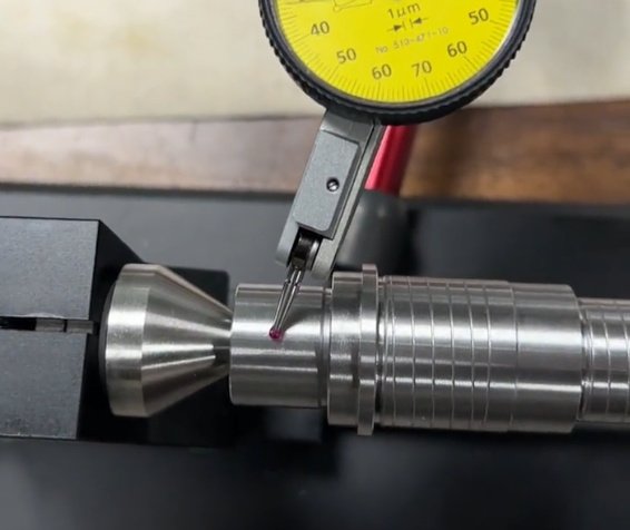
Straightness and Runout
Straightness is critical for linear motion shafts and long rotating shafts. Excessive straightness deviation results in uneven bearing loads, higher friction, and positioning errors. Runout, especially on journals and critical mounting surfaces, affects vibration, noise, and tool or workpiece accuracy in spindles.
Hardness and Case Depth
Surface hardness determines resistance to wear, indentation, and fretting. Induction-hardened or case-hardened shafts often provide a hard, wear-resistant surface with a tough core. Case depth must be adequate for the expected contact stresses and bearing load zones. Through-hardened shafts offer uniform hardness but can be more brittle and less forgiving under impact.
| Parameter | Typical Range for Precision Shafts | Common Application Context |
|---|---|---|
| Diameter tolerance | h5, h6, h7 (e.g., -0 / -0.008 mm for 10–18 mm h6) | Linear guides, bearing journals, alignment shafts |
| Straightness | ≤ 0.1–0.2 mm per 1000 mm (high-precision linear shafts can be tighter) | Linear motion shafts, long drive shafts |
| Surface roughness Ra | ≈ 0.2–0.8 µm for ground; 0.8–1.6 µm for turned and polished | Linear bearings, rotary bearings, seal interfaces |
| Hardness (surface) | ≈ 55–62 HRC for hardened shafts; 160–300 HB for non-hardened | Wear-critical linear bearings, spindles, drive shafts |
| Runout (radial) | Commonly ≤ 0.01–0.02 mm on critical journals | Spindles, precision rotary axes |
Materials for Precision Shafts
Material selection determines mechanical strength, machinability, corrosion resistance, and cost. The choice depends on operating environment, loads, required life, and interface with bearings or other components.
Carbon and Alloy Steels
Plain carbon steels and low-alloy steels are widely used for mechanical shafts due to good balance of strength, machinability, and cost. Medium-carbon steels are commonly used for shafts requiring heat treatment for higher strength and wear resistance. Alloy steels offer improved hardenability and toughness for heavy-duty or high-speed applications.
Stainless Steels
Stainless steel shafts are selected for environments with moisture, chemicals, or stringent cleanliness requirements, such as food processing, pharmaceutical equipment, and outdoor systems. Austenitic grades provide excellent corrosion resistance and good toughness but lower hardness unless cold worked. Martensitic and precipitation-hardening grades allow higher hardness and wear resistance while retaining corrosion resistance.
Aluminum and Lightweight Alloys
Aluminum shafts are used when low mass and reduced inertia are priorities, such as in robotics, light-duty actuators, and devices requiring rapid acceleration. While their stiffness and surface hardness are lower than steels, suitable anodizing and larger diameters can compensate for some limitations. Other lightweight options include titanium alloys for specialized high-strength, low-density needs.
Coatings and Surface Treatments
Surface treatments expand the performance range of base materials. Hard chrome plating increases wear resistance and reduces friction on steel shafts. Nickel plating improves corrosion resistance and offers a bright finish. Nitriding or nitrocarburizing introduces a hard surface layer with limited distortion, suitable for precision parts. Phosphate coatings, black oxide, and other treatments support lubrication and corrosion control depending on application conditions.
Precision Shaft Applications by Industry
Precision shafts appear in a broad range of industries and equipment types, each with characteristic design and performance requirements.
Machine Tools and Metalworking Equipment
In machine tools, shafts are used for spindle assemblies, feed screws, drive shafts, and guide systems. Spindle shafts must withstand high rotational speeds, cutting forces, and thermal effects while maintaining low runout and high rigidity. Feed shafts and drive shafts transmit power to lead screws, ballscrews, and gear trains, requiring controlled torsional stiffness and accurate interfaces with bearings and couplings.
Automation, Robotics, and Motion Control
Automation equipment uses precision shafts as linear guides, actuator rods, and joint axes. Robot joints rely on shafts for transmitting torque between motors and links, often arranged with harmonic drives, planetary gearboxes, or belt drives. Positioning systems rely on straight, smooth shafts with linear bearings or bushings for accurate motion.
Pumps, Compressors, and Fans
In rotating fluid machinery, shafts connect motors to impellers, rotors, and couplings. Shaft design must take into account bending loads from rotor weight and hydraulic forces, as well as torsional loads from starting and transient conditions. Proper selection of shaft material and surface finish for seal areas and bearing journals is important for fluid sealing and long bearing life.
Printing, Packaging, and Textile Machinery
Printing rollers, conveyor drive shafts, and guide rollers rely on consistent shaft geometry to maintain web tracking, tension, and print registration. These applications often involve multiple shafts in parallel, making straightness and diameter consistency critical. Surface treatments may be chosen to resist wear from paper, films, fabrics, or abrasive media.
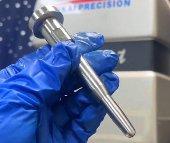
Medical Devices and Laboratory Equipment
In medical and laboratory systems, compact shafts support small actuators, pumps, and positioning stages. Requirements commonly include low particle generation, corrosion resistance, and compatibility with sterilization processes. Stainless shafts, miniature diameters, and finely ground finishes are frequently specified for these applications.
| Industry | Representative Shaft Functions | Key Requirements |
|---|---|---|
| Machine tools | Spindle shafts, feed shafts, guide shafts | Low runout, high stiffness, controlled thermal behavior |
| Automation and robotics | Linear guides, actuator rods, rotary axes | High positional accuracy, low friction, weight optimization |
| Pumps and compressors | Drive shafts, rotor shafts, coupling shafts | Fatigue strength, seal surface quality, corrosion resistance |
| Packaging and printing | Roller shafts, conveyor drive shafts | Straightness, diameter consistency, surface durability |
| Medical and lab equipment | Miniature actuator shafts, guide rods | Cleanliness, corrosion resistance, precise finish |
Integration with Bearings, Couplings, and Drive Elements
Shaft performance is closely linked to interface conditions with bearings, couplings, gears, pulleys, and other components.
Bearing Seats and Journals
Bearing seats must provide the correct fit, support concentricity, and maintain stability under load and temperature changes. For rolling bearings, shaft seat tolerances and shoulder geometry are critical to prevent bearing misalignment and uneven load distribution. For sliding bearings or bushings, surface finish, hardness, and lubrication conditions must be controlled to avoid scoring and excessive wear.
Couplings, Gears, and Pulleys
Shafts transmit torque to couplings, gears, and pulleys through keyways, splines, interference fits, or clamping hubs. The interface design must ensure adequate torque capacity, avoid stress concentrations, and allow assembly and removal. Balance and alignment of these components relative to the shaft axis influence vibration and service life.
Sealing and Lubrication Interfaces
Shaft seals, such as rotary lip seals or mechanical seals, require appropriate surface hardness and finish in the seal contact area. Rough or damaged surfaces increase leakage and shorten seal life. For lubricated systems, grooves, oil holes, or lubrication channels may be integrated into the shaft design to maintain sufficient lubricant supply to bearings and sliding interfaces.
Machining and Manufacturing Methods
Manufacturing routes for precision shafts combine various forming, machining, and finishing processes. The selected sequence must achieve required tolerances, minimize distortion, and maintain cost efficiency.
Turning, Grinding, and Polishing
Turning is typically used to rough- and semi-finish shaft diameters and features such as steps, shoulders, and threads. Grinding operations then refine critical diameter and shape tolerances. Centerless grinding is common for long shafts and cylindrical surfaces, while between-center grinding suits shafts with defined centers. Polishing or superfinishing can further improve surface roughness and bearing contact quality.
Heat Treatment and Straightening
Heat treatment processes such as quenching and tempering or induction hardening enhance strength and wear resistance. However, they can introduce distortion or warping. Post-heat-treatment straightening and corrective grinding are often required for high-precision shafts. For linear shafts, straightness control after hardening and grinding is especially important.
End Machining and Feature Integration
Practical shafts often require end machining for threads, wrench flats, retaining ring grooves, or custom interfaces. These operations must be planned to maintain alignment and dimensional accuracy. If keyways, splines, or cross holes are needed, their position relative to reference diameters and faces should be defined in the drawing and inspection process.
Assembly, Alignment, and Installation Considerations
Even accurately manufactured shafts can underperform if assembly and installation are not controlled. Attention to handling, alignment, and fit during installation ensures that dimensional precision translates into system performance.
Handling and Preparation
Precision shafts should be handled to avoid impact damage, nicks, or corrosion. Protective sleeves, oil coatings, or packaging are commonly used during storage and transport. Before assembly, surfaces should be cleaned of dust, debris, and preservative oils when necessary, while maintaining a thin lubricating layer where specified.
Alignment and Support Conditions
During installation, the alignment between shaft and bearings, housings, or guides must be verified. Misalignment can increase friction, heat, and load concentrations, shortening component life. For linear shafts, support mounting surfaces must be flat and properly spaced to avoid forcing the shaft into a bent condition. For rotating shafts, angular and radial alignment with coupling partners is essential to minimize vibration.
Fits, Preload, and Fastening
The chosen fits between shaft and mating elements influence assembly methods and operating behavior. Interference fits may require thermal expansion methods or pressing tools for assembly and disassembly. Clearance fits ease assembly but must still prevent excessive play or fretting. For systems using preloaded bearings or clamped hubs, axial positioning and tightening sequences should be controlled so that preload remains within specified limits.
Operational Performance and Maintenance
After installation, shaft performance depends on operating conditions, lubrication, and maintenance practices. Regular monitoring and preventive maintenance support long service life and stable performance.
Lubrication and Wear Control
Adequate lubrication minimizes friction, wear, and heat generation at shaft interfaces with bearings, seals, and sliding contacts. Lubricant type, viscosity, and lubrication intervals must be matched to speed, load, and environment. Contamination control through seals and filtration is equally important, as abrasive particles can damage shaft surfaces and accelerate wear.
Inspection and Condition Monitoring
Periodic inspection of vibration levels, noise, temperature, and visual shaft condition provides early indication of problems. Surface scoring, discoloration, fretting corrosion, or seal leakage can point to misalignment, overload, or insufficient lubrication. Where high precision is required, runout and straightness checks may be performed during scheduled maintenance.
Replacement and Interchangeability
When shafts are designed with standard diameters, tolerances, and interface features, replacement is simplified. Documentation of shaft specifications, including material, hardness, and surface finishing, supports consistent performance when spares are manufactured or sourced from alternate suppliers.
Typical Considerations and Issues in Precision Shaft Applications
Several common issues recur in the design and use of precision shafts.
Deflection and Vibration
Long or slender shafts can deflect under load and exhibit unwanted vibration or resonance. This can reduce accuracy in machine tools, cause belt tracking issues in conveyors, or increase noise and wear. Designers must check bending deflection, torsional twist, and critical speed relative to operating conditions and adjust diameter, support spacing, or material accordingly.
Fit-Related Assembly Difficulties
Incorrectly specified fits can lead to assembly problems or operational looseness. Excessive interference fit may require high assembly force or cause material yielding. Too much clearance can lead to play, noise, and fretting. Proper definition of tolerance classes, along with suitable installation tools, helps avoid these complications.
Surface Damage and Corrosion
Precision shafts with finely ground surfaces are vulnerable to handling damage and corrosion if not protected. Minor nicks can disrupt bearing travel, increase localized stress, or impair sealing. Appropriate packaging, storage, and protective coatings, as well as controlled cleaning procedures, help preserve surface integrity throughout the product life cycle.
Guidelines for Specifying Precision Shafts
An effective specification ensures that the shaft design aligns with functional and manufacturing requirements. The following aspects are commonly defined in engineering drawings and purchasing documents:
Geometry: diameter, length, steps, chamfers, shoulders, and reference features.
Material: grade, heat treatment condition, and any special requirements for cleanliness or traceability.
Tolerances: diameter tolerances and fit classes, straightness, concentricity, runout, and length tolerances as needed.
Surface finish: specified roughness values for functional surfaces such as bearing journals, seal areas, and sliding regions.
Hardness: surface hardness value and case depth where applicable, including verification method.
Special features: keyways, splines, threads, cross holes, flats, and end configurations for mounting and coupling.
Surface treatments: plating, nitriding, black oxide, or other specified coatings for corrosion or wear resistance.
