
Precision CNC milling is a subtractive manufacturing process that uses computer-controlled rotary cutting tools to remove material from a solid workpiece, creating accurate, repeatable geometries for custom and production parts. It supports metals, plastics, and advanced engineering materials, covering prototypes through high-volume orders with consistent quality.
What Is Precision CNC Milling
Precision CNC milling uses programmed toolpaths to move cutting tools relative to a fixed or moving workpiece, producing prismatic and complex 3D shapes with tight tolerances. It is a core process for components that require accurate dimensions, precise mating features, and controlled surface finishes.
The workflow typically includes CAD model creation, CAM programming, machine setup, cutting operations, in-process inspection, and final quality verification. Automated control of feed rates, spindle speeds, and tool positions enables consistent results from part to part.
CNC Milling Capabilities and Machine Types
CNC milling machines differ in axis configuration, size, and automation level. Choosing the appropriate system depends on part geometry, tolerance requirements, and production volume.
3-Axis Milling
3-axis milling moves the cutting tool along X, Y, and Z axes. It is suitable for most prismatic parts, pockets, slots, and basic 3D contours.
- Common for flat surfaces, simple cavities, and drilled holes
- Efficient for rectangular housings, plates, brackets, and fixtures
- Lower setup complexity and cost compared to multi-axis systems
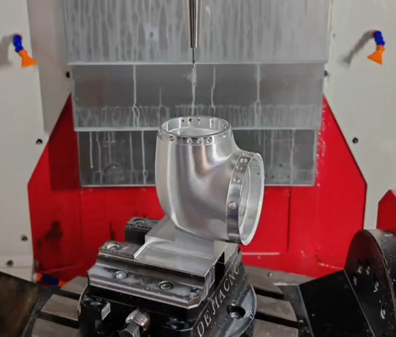
4-Axis Milling
4-axis milling adds a rotary axis (typically A or B) that allows rotation of the workpiece. This reduces setups for parts with features on multiple sides.
4-axis systems are effective for components such as flanges, manifolds, and parts requiring radial features or multiple side machining in a single setup.
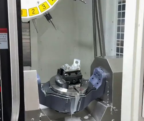
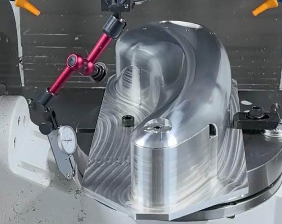
5-Axis Milling
5-axis milling includes two rotary axes in addition to the three linear axes. This allows the cutting tool to approach the part from almost any direction.
Advantages include:
- Machining complex 3D profiles, undercuts, and freeform surfaces
- Reducing number of setups and fixtures
- Improved accuracy between multi-sided features
5-axis milling is widely used for aerospace components, turbine blades, medical implants, and intricate tooling.
Horizontal vs. Vertical Milling Centers
Vertical machining centers (VMCs) orient the spindle vertically and are widely used for a broad range of parts. Horizontal machining centers (HMCs) orient the spindle horizontally and often include pallet changers and multi-face fixturing.
HMCs can improve chip evacuation and are commonly used for higher-volume production when multiple faces of a part must be machined in one cycle. VMCs are often preferred for prototypes, custom parts, and small to medium production runs due to more straightforward setups.
Materials Commonly Used for CNC Milled Parts
CNC milling supports a wide selection of metals and plastics. Material choice is driven by mechanical performance, cost, machinability, and environmental conditions.
| Material Group | Examples | Key Properties | Typical Applications |
|---|---|---|---|
| Aluminum Alloys | 6061-T6, 6082, 7075-T6, 2024 | Lightweight, good strength-to-weight, excellent machinability, corrosion resistance | Housings, brackets, jigs, enclosures, automotive and aerospace structural parts |
| Carbon & Alloy Steels | 1018, 1045, 4140, 4340 | High strength, toughness, heat treatable, good wear resistance | Shafts, gears, fixtures, machine components, structural elements |
| Stainless Steels | 303, 304, 316, 17-4 PH | Corrosion resistance, high strength, good temperature performance | Medical devices, food equipment, marine parts, precision hardware |
| Tool Steels | D2, O1, A2, H13 | High hardness, wear resistance, dimensional stability | Molds, dies, cutting tools, wear plates |
| Copper Alloys | Brass (C360), Bronze, Copper C110 | Excellent electrical and thermal conductivity, good machinability (brass) | Connectors, terminals, heat sinks, decorative parts |
| Titanium Alloys | Ti-6Al-4V | High strength-to-weight, corrosion resistance, biocompatibility | Aerospace hardware, medical implants, high-performance fasteners |
| Engineering Plastics | POM (Delrin), PEEK, PC, PA, ABS | Low weight, electrical insulation, chemical resistance, low friction | Insulators, bushings, manifolds, medical components, housings |
Key Dimensional Tolerances in CNC Milling
Dimensional tolerances specify permissible variation from nominal dimensions. Precision CNC milling can consistently achieve tight tolerances when supported by accurate machines, stable fixturing, and robust inspection procedures.
Typical general machining tolerances for many milled parts are around ±0.05 mm to ±0.10 mm. With appropriate process controls, precision milling can reach ±0.01 mm or tighter on critical features, depending on material, geometry, and part size.
| Feature Type | Standard Tolerance Range | Precision Tolerance Range | Notes |
|---|---|---|---|
| Linear dimensions | ±0.05–0.10 mm | ±0.005–0.02 mm | Dependent on length, material, and inspection method |
| Hole diameters (reamed/boring) | ±0.05 mm | ±0.005–0.015 mm | Tighter fits achievable with reaming, boring, or honing |
| Flatness | 0.05–0.10 mm per 100 mm | 0.01–0.02 mm per 100 mm | Influenced by part size, clamping, and stress relief |
| Perpendicularity | 0.05–0.10 mm per 100 mm | 0.01–0.02 mm per 100 mm | Critical for mating assemblies and bearing locations |
| Position tolerance (true position) | ±0.10–0.20 mm | ±0.01–0.05 mm | Used with GD&T for hole patterns and critical features |
Feasible tolerances depend on the combination of material, part size, feature location, and measurement capability. Explicit tolerance specifications should be aligned with functional requirements while remaining manufacturable.
Surface Finishes and Edge Conditions
CNC milling produces surfaces characterized by toolpath marks and material-specific textures. Surface finish is typically described using roughness parameters such as Ra (arithmetical mean roughness).
Typical as-milled surface roughness values range from approximately Ra 1.6 to 3.2 µm for finishing operations. More refined surfaces can be achieved through optimized cutting parameters or secondary processes.
Common surface treatments for CNC milled parts include:
- Anodizing (for aluminum) for corrosion resistance and appearance
- Plating (nickel, zinc, chrome) for wear or corrosion protection
- Passivation (stainless steel) for enhanced corrosion resistance
- Bead blasting for uniform matte surfaces
- Powder coating or painting for functional and cosmetic purposes
Edge conditions are also important. Functional edges may require chamfers or radii for assembly, safety, and stress reduction. Typical machined chamfers range from 0.2 mm to 1.0 mm, while fillets often range from 0.5 mm upward, depending on design and tooling.
From Prototypes to Production Runs
Precision CNC milling supports all production stages, from initial prototypes to long-term production.
Prototyping and One-Off Parts
For prototypes and custom parts, CNC milling enables rapid, accurate evaluation of fit, function, and assembly. Design changes can be implemented quickly at the CAD/CAM level, with minimal tooling lead time. This is suitable for engineering prototypes, pre-production samples, and spare parts.
Low-Volume and Bridge Production
Low-volume production covers typical order quantities ranging from tens to several hundreds of parts. CNC milling is well-suited for bridge production between prototype and full-scale manufacturing, especially when tooling for other processes (such as die casting or molding) is not yet justified.
High-Volume Production
With optimized fixturing, multi-pallet systems, and standardized tool libraries, CNC milling can serve high-volume production requirements. Automation elements such as pallet changers, bar feeders (for mill-turn setups), and part probing enable extended unattended machining and consistent output. Cost per piece is reduced by minimizing cycle time and setup changeovers.
Critical Design Considerations for CNC Milled Parts
Design practices strongly affect machining time, cost, and achievable tolerances. Applying machinability-oriented guidelines helps balance performance and manufacturability.
Wall Thickness and Pocket Depth
Excessively thin walls or deep pockets can lead to vibration, deflection, and dimensional instability. As a general guideline:
For metals, wall thickness below approximately 0.5–0.8 mm becomes difficult to machine in larger areas. For plastics, higher minimum thickness is usually required due to lower stiffness. Pocket depths beyond 3–4 times the tool diameter can significantly increase machining time and risk of tool deflection, especially for small end mills.
Corners, Radii, and Internal Geometry
End mills have a finite diameter, so internal corners cannot be perfectly sharp. Providing internal radii that match common tool sizes reduces tool changes and improves surface quality.
Internal corner radii are commonly set at 0.5–3.0 mm, depending on part scale. Larger radii improve tool life and reduce machining time. For critical sharp corners, secondary processes such as EDM may be required, which increase cost and lead time.
Tapped Holes and Threaded Features
Threaded holes are frequent in milled parts. Design should specify thread type (metric or unified), pitch, and depth. Practical guidelines include:
Effective thread engagement around 1–1.5 times the nominal diameter is often sufficient for strength, depending on material. Blind holes should include additional depth for chip accumulation and tap clearance. Specifying overly deep threads increases machining time without significant benefit.
Tolerances and GD&T
Excessively tight tolerances increase inspection time, scrap risk, and cost. Tolerances should be applied selectively to function-critical features such as bearing bores, sealing surfaces, and alignment interfaces.
Using geometric dimensioning and tolerancing (GD&T) allows explicit control of form, orientation, and position. Proper datum selection and consistent reference frames are important for reliable measurement and repeatable manufacturing.
Workholding, Fixturing, and Stability
Workholding strategy directly affects accuracy, surface finish, and cycle time. For many prismatic parts, standard vises, clamps, and modular fixtures are sufficient. More complex components may require dedicated fixtures to control alignment and minimize distortion.
Key considerations for fixturing include:
Ensuring adequate clamping force without deforming the part, especially for thin sections. Providing clear access for tools to reach all features in as few setups as possible. Designing locating surfaces that are consistent with drawing datums. Maintaining stable conditions when machining multiple identical parts in a single setup.
For high-volume production, dedicated fixtures and quick-change systems can significantly reduce setup time and improve repeatability.
Tooling, Cutting Parameters, and Process Control
Cutting tools and process parameters determine machining efficiency and part quality. End mills, face mills, drills, and specialized cutters are selected based on material, geometry, and required surface finish.
Key parameters include spindle speed, feed rate, axial and radial depth of cut, and tool engagement. Balanced selection of these parameters controls tool wear, chip evacuation, and dimensional accuracy. Coolant or lubrication type (flood, mist, dry machining) is selected according to material and tool requirements.
Process control may include in-process probing, tool length and diameter compensation, and adaptive feed controls. Structured toolpath strategies, such as high-speed machining for hard materials or trochoidal milling for deep pockets, help maintain stable cutting conditions.
Quality Assurance and Inspection
Quality assurance verifies that parts meet dimensional, geometric, and visual requirements. Inspection plans typically define sampling levels, measurement methods, and acceptance criteria.
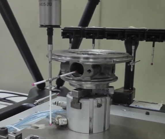
Common inspection tools and methods include:
- Calipers, micrometers, height gauges, and gauge blocks for basic dimensions
- Coordinate measuring machines (CMM) for complex geometries and GD&T features
- Surface roughness testers for Ra and related parameters
CMM inspection is common for critical components in aerospace, medical, and automotive applications where high confidence in measurement data is required. Statistical process control (SPC) can be applied in high-volume production to monitor key dimensions and maintain process capability.
Applications of Precision CNC Milled Parts
Precision CNC milling supports a wide range of industries, including:
Aerospace and defense: structural components, brackets, housings, actuator parts, and mounting hardware. Automotive and motorsport: engine parts, transmission components, suspension elements, and prototype parts. Medical and dental: surgical instruments, implant components, housings for diagnostic equipment, and fixtures. Industrial equipment: machine components, gear housings, manifolds, and tooling. Electronics: heat sinks, enclosures, connector housings, and precision mechanical parts for instrumentation.
Because CNC milling can handle both metals and engineering plastics, it is suitable for integrated assemblies that require both structural and insulating components.
Cost Factors and Practical Considerations
Several factors influence the cost and lead time of CNC milled parts, including:
Part complexity: intricate 3D surfaces, deep cavities, or numerous features increase programming and machining time. Material selection: hard-to-machine materials may require more expensive tooling and slower cutting parameters. Quantity: per-piece cost decreases as quantity increases, due to spreading setup time over more parts. Tolerances and surface finish: tighter tolerances and smoother finishes extend machining and inspection time. Secondary operations: heat treatment, surface finishing, and assembly add cost and lead time.
When specifying parts, aligning tolerances, material, and finish with functional requirements leads to more efficient manufacturing and better cost control.
Typical Issues for Engineering and Purchasing Teams
In practical use, several issues commonly arise:
Drawings that include unnecessarily tight tolerances on non-critical dimensions, leading to higher quotes and longer lead times. Features that are difficult or impossible to access with standard tools, causing extra setups or the need for specialty tooling. Incomplete documentation of material specifications, heat treatments, or surface finishes, causing ambiguity and delays. Limited communication between design and manufacturing teams, resulting in multiple design iterations after initial manufacturing review.
Addressing these points through clear drawings, early manufacturability reviews, and accurate specification of requirements improves outcomes for both custom and production parts.
