

Metal CNC machining is a subtractive manufacturing process that uses computer numerical control to remove material from metal workpieces and produce precise, repeatable components. It is widely used for prototypes, low-volume parts, and mass production where dimensional accuracy, stability and surface quality are critical.
Fundamentals of Metal CNC Machining
Metal CNC machining relies on programmed toolpaths to coordinate cutting tools and workpiece motion. Tool movements along multiple axes are defined by G-code, which is generated from CAD models via CAM software. The process is highly controlled, enabling consistent tolerance and surface finish across batches.
The machining workflow typically includes:
- Designing the part in CAD and defining datum features
- Generating CAM toolpaths with appropriate tools and cutting parameters
- Fixturing and zero-point alignment on the machine
- Roughing, semi-finishing, and finishing operations
- Inspection and dimensional verification
Metal CNC machining differs from plastics machining mainly in cutting forces, heat generation, tool wear, and rigidity requirements, all of which must be considered when choosing machines, tools, fixtures, and process parameters.
Common Metals Used in CNC Machining
The choice of metal affects machinability, achievable tolerance, surface finish, and cost. Mechanical properties, chip formation behavior, and thermal properties also influence tool life and cycle time.
| Material | Typical Grades | Machinability (relative) | Key Attributes | Typical Applications |
|---|---|---|---|---|
| Aluminum | 6061-T6, 6082, 7075, 2024 | Very good | Low density, good thermal conductivity, easily machined, good corrosion resistance (some grades) | Housings, fixtures, automotive components, aerospace parts, jigs |
| Carbon Steel | 1018, 1020, 1045, 1215 | Good to excellent (free-cutting grades) | High strength, low cost, can be hardened, may require corrosion protection | Shafts, gears, pins, brackets, structural parts |
| Alloy Steel | 4140, 4340, 8620 | Moderate | Higher strength and toughness, heat-treatable, often used where fatigue and wear resistance are needed | Powertrain components, tools, high-load machine parts |
| Stainless Steel | 303, 304, 316, 17-4PH | Fair to good | Corrosion resistance, hygienic, some grades hard to machine, work hardening | Medical devices, food equipment, marine components, fasteners |
| Copper | C110, C101 | Good but sticky | High electrical and thermal conductivity, tends to form burrs and built-up edge | Electrical connectors, busbars, heat sinks |
| Brass | C360, C464 | Excellent | Free machining, good dimensional stability, good corrosion resistance | Fittings, valves, instrumentation parts, decorative hardware |
| Bronze | C932, C954 | Good | Wear resistance, good sliding properties, often used for bushings | Bearings, bushings, guide components |
| Titanium | Grade 2, Grade 5 (Ti-6Al-4V) | Difficult | High strength-to-weight, corrosion resistance, low thermal conductivity | Aerospace parts, medical implants, high-performance fasteners |
| Nickel Alloys | Inconel 718, Monel 400 | Difficult | High-temperature strength, corrosion resistance, work hardening | Gas turbine components, chemical processing equipment |
Material selection must account for hardness, tensile strength, thermal conductivity, and machinability ratings, which influence tool selection, cutting speeds, and coolant requirements.
Key CNC Machining Methods for Metals
Metal machining uses a variety of CNC-controlled processes. Each method is suited to particular part geometries, tolerances, and production volumes.
CNC Milling
CNC milling uses rotating multi-point cutting tools to remove material while the workpiece is fixed or moved on multiple axes. Common machine configurations include 3-axis vertical and horizontal mills, as well as 4-axis and 5-axis machining centers for more complex geometries.
Typical milling operations include:
- Face milling for planar surfaces and overall stock removal
- End milling for pockets, slots, and side features
- Contour and 3D surface milling for complex freeform shapes
Milling is suitable for prismatic parts, enclosures, brackets, plates, and components where multiple faces require machining.
CNC Turning
CNC turning rotates the workpiece while stationary tools remove material to create cylindrical or conical shapes. Lathes typically operate on 2 axes (X and Z), with live tooling and sub-spindles enabling milling operations on the same setup.
Turning operations include facing, OD/ID turning, grooving, threading, and boring. It is ideal for shafts, bushings, fasteners, rings, and any rotationally symmetric parts.
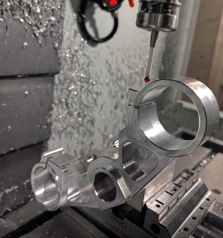
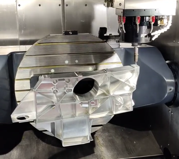
Multi-Axis and Mill-Turn Machining
Multi-axis machining (4-axis and 5-axis) enables tool orientation changes and machining on multiple sides in a single setup. Mill-turn centers combine turning with full milling capability, reducing setups and improving positional accuracy between features.
These platforms are preferred for complex metal parts requiring tight positional relationships between features on different faces.
Auxiliary Machining Processes
In addition to primary milling and turning, metal CNC machining often includes:
Drilling, reaming, and tapping: for precise holes, hole finishing, and threads. Reaming improves hole size and surface finish beyond what drilling alone can achieve.
Boring: enlarges existing holes to achieve tight tolerances and alignment.
Broaching (sometimes via dedicated machines): used for internal keyways or spline profiles.
These operations are commonly integrated into the same CNC setup to minimize repositioning and maintain datum control.
Dimensional Accuracy and Tolerances
Dimensional accuracy in metal CNC machining depends on machine capability, tool condition, fixturing, thermal stability, and process control. Tolerances describe the permissible deviation from nominal dimensions.
| Feature Type | Typical Tolerance Range (standard commercial work) | Notes |
|---|---|---|
| Linear dimensions (milled) | ±0.05 mm to ±0.10 mm | Tighter tolerances possible (±0.01–0.02 mm) with appropriate setup and process |
| Linear dimensions (turned) | ±0.01 mm to ±0.03 mm | Turning usually achieves higher accuracy on diameters |
| Bore diameters | ±0.01 mm to ±0.025 mm | Using boring bars or reamers; tighter fits may require honing or grinding |
| Flatness (faces) | 0.02 mm to 0.05 mm per 100 mm | Dependent on machine geometry and part size |
| Concentricity (turned features) | 0.01 mm to 0.03 mm | Improved with one-piece setups and high-precision chucks |
| Position tolerance (hole patterns) | ±0.05 mm to ±0.10 mm | Dependent on datum strategy and measurement method |
Higher precision (e.g., tolerances below ±0.005 mm) usually requires specialized high-precision machines, climate-controlled environments, controlled tool wear, and often secondary processes such as grinding or lapping.
Surface Finish in Metal Machining
Surface finish affects sealing performance, fatigue behavior, friction, and appearance. In metal CNC machining, surface roughness is commonly specified as Ra (arithmetical mean roughness) in micrometers (µm) or microinches.
Typical machined surface ranges:
- Roughing passes: Ra 3.2–6.3 µm (125–250 µin)
- Standard finishing passes: Ra 0.8–3.2 µm (32–125 µin)
- Fine finishing: Ra 0.2–0.8 µm (8–32 µin)
Tool nose radius, feed per revolution, cutting speed, and tool geometry significantly influence roughness. Turned surfaces often achieve finer finishes than milled surfaces for similar parameters due to continuous cutting.
When required, secondary finishing processes can be used:
Grinding: for surfaces requiring very low Ra (down to <0.1 µm) and tight size control.
Honing and lapping: to refine bores and critical sealing or bearing surfaces.
Polishing: for appearance and some functional requirements, especially on stainless steel and aluminum.
Process Parameters and Their Impact
Metal CNC machining performance is strongly influenced by cutting parameters. Key parameters include cutting speed, feed rate, depth of cut, and tool engagement angle.
Cutting Speed and Spindle Speed
Cutting speed is defined at the tool-workpiece interface, usually in meters per minute (m/min) or surface feet per minute (SFM). Spindle speed is derived from cutting speed and tool diameter. Typical cutting speed ranges (approximate) for carbide tools:
Aluminum alloys: roughly 200–800 m/min
Carbon steel: roughly 150–300 m/min
Stainless steel: roughly 80–200 m/min
Titanium: roughly 40–120 m/min
Nickel alloys: roughly 20–80 m/min
Actual values depend on tool material, coating, coolant, machine rigidity, and required tool life.
Feed Rate and Depth of Cut
Feed rate is typically specified as feed per tooth (mm/tooth) for milling and feed per revolution (mm/rev) for turning. Larger feeds increase material removal rate but can worsen surface finish and increase cutting forces.
Depth of cut (axial and radial for milling, radial for turning) defines how much material is removed per pass. Roughing uses larger depths to maximize productivity, whereas finishing uses smaller depths to minimize deflection and achieve tight tolerances.
Tool Materials and Coatings
Common tool materials for metal machining include:
Cemented carbide: widely used due to high hardness and wear resistance.
High-speed steel (HSS): used mainly in drills and taps, particularly in less rigid setups or for certain stainless steels.
Cermet, ceramic, CBN, PCD: used for specific applications such as hardened steels or non-ferrous alloys.
Coatings such as TiN, TiAlN, AlTiN and others enhance wear resistance, thermal stability, and reduce friction, enabling higher cutting speeds and longer tool life in many metals.
Coolant and Lubrication
Coolants remove heat and flush chips, while lubricants reduce friction and improve surface finish. Metal CNC machining often uses flood coolant, high-pressure coolant, or minimum quantity lubrication (MQL) depending on material and process.
Certain materials, such as titanium and nickel alloys, benefit strongly from high-pressure coolant to break chips and control heat, while some aluminum operations may run dry or with minimal lubrication to avoid contamination and corrosion issues.
Fixturing, Workholding, and Stability
Stable and repeatable fixturing is essential for dimensional accuracy and surface quality in metal machining. Workholding must resist cutting forces and prevent vibration or micro-movement that can cause chatter and dimensional deviations.
Typical workholding solutions include:
Vises: for prismatic parts, with soft jaws or custom jaws to adapt to geometry.
Chucks and collets: for turned parts and round stock.
Clamping systems and modular fixtures: for plates and complex components.
Zero-point clamping systems: to speed up changeovers while maintaining datum repeatability.
Fixturing design must consider clamping force distribution, part deformation, accessibility for cutting tools, and space for chip evacuation.
Programming, Toolpaths, and CAM Strategy
Toolpath strategy directly affects cycle time, tool wear, dimensional stability, and surface integrity. CAM software is used to generate optimized toolpaths based on the CAD model and chosen machining sequence.
Roughing, Semi-Finishing, and Finishing
Roughing toolpaths focus on high material removal rates with robust tools and conservative tolerance allowances. Semi-finishing is used where necessary to equalize stock for a final finishing pass. The finishing pass defines the final dimension and surface.
Leaving a controlled amount of stock (e.g., 0.2–0.5 mm on walls, 0.1–0.3 mm on floors) before finishing helps compensate for tool deflection during roughing and ensures uniform cutting conditions in the final pass.
Toolpath Types
For milling, common toolpaths include:
2D contouring and pocketing: for slots, pockets, and perimeters.
Adaptive or high-efficiency roughing: maintains constant tool engagement to reduce tool load and heat.
Parallel, scallop, and radial finishing: for 3D surfaces and freeform geometry.
For turning, typical paths include longitudinal turning, facing, profiling, grooving, and threading, with careful control of entry and exit moves to protect surface integrity.
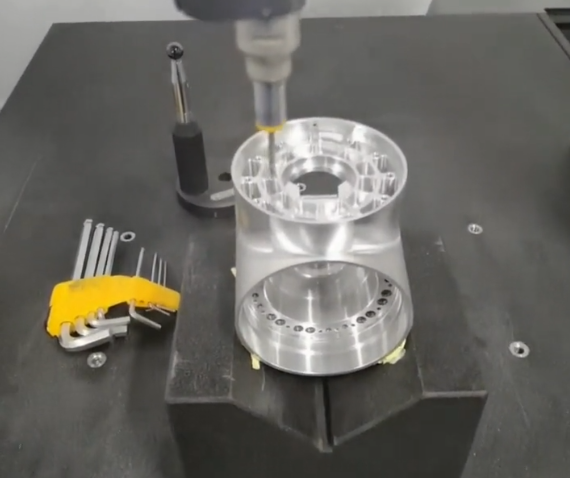
Metrology and Quality Control
Verification of metal CNC parts is critical to ensure that design requirements and functional specifications are met. Quality control includes dimensional inspection, surface measurement, and sometimes material property verification.
Inspection Methods
Common inspection tools and methods include:
Calipers and micrometers: for basic dimensions and diameters.
Height gauges and surface plates: for heights, depths, and flatness verification.
Gauge pins and bore gauges: for holes and bores.
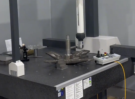
Coordinate Measuring Machines (CMM): for complex geometries, GD&T features, and automated inspection routines.
Optical and vision systems: for small parts, complex profiles, and non-contact measurements.
Surface roughness testers: to quantify Ra and other roughness parameters.
Process Control Considerations
To maintain consistent precision in metal CNC machining over multiple batches, operators often control:
Tool wear compensation: updating tool offsets based on measured deviation.
Thermal effects: managing coolant temperature, machine warm-up cycles, and shop climate.
Datum and reference strategies: clear definition of reference surfaces and datums in both CAD and inspection plans.
Traceability: recording inspection data and measurement conditions for quality documentation and process improvement.
Typical Issues in Metal CNC Machining
While metal CNC machining is highly capable, certain recurring issues must be managed for stable production and predictable costs.
Tool Wear and Tool Life
Harder metals, high cutting speeds, and interrupted cuts can accelerate tool wear. Excessive wear leads to dimensional drift, poor surface finish, and increased risk of tool breakage. Establishing tool life limits and using wear monitoring or scheduled tool changes helps maintain consistent quality.
Heat and Thermal Deformation
Heat generated during cutting can cause local expansion of the workpiece and the machine structure. This can result in features measuring differently immediately after machining compared to after cooling. Proper coolant use, balanced cutting parameters, and temperature-stable environments reduce these effects.
Chatter and Vibration
Insufficient rigidity in the tool, workpiece, or fixturing can lead to chatter, which appears as a wavy surface pattern and affects tolerances. Solutions include optimizing tool overhang, using more rigid holders, adjusting spindle speed to avoid resonance, and modifying depth of cut and feed.
Chip Evacuation
In some metals, such as aluminum and certain stainless steels, chips can be long and stringy, causing entanglement, re-cutting, and surface damage. Effective chip break geometries, correct feed and depth, and properly directed coolant help manage chip evacuation.
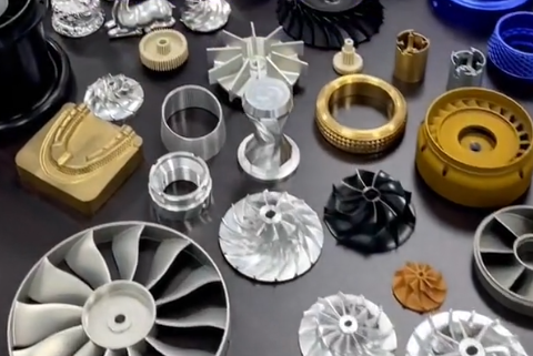
Applications of Metal CNC Machining
Metal CNC machining is used across many industries where mechanical performance, dimensional accuracy, and repeatability are required.
Representative applications include:
Aerospace: structural components, brackets, actuators, housings, landing gear components.
Automotive and motorsport: engine parts, transmission components, suspension parts, custom tooling.
Medical: implant components, surgical instruments, diagnostic equipment parts.
Industrial machinery: gears, shafts, couplings, machine bases, tooling plates.
Energy and power: turbine components, heat exchanger parts, valve bodies.
Electronics and instrumentation: enclosures, heatsinks, precision frames and carriers.
FAQ About Metal CNC Machining
What is metal CNC machining?
Metal CNC machining is a manufacturing process where computer-controlled machines cut, shape, or drill metal parts with high precision. It’s widely used in industries like aerospace, automotive, and electronics.
What types of metals can be used in CNC machining?
Common metals include aluminum, steel, stainless steel, brass, copper, and titanium. Each metal has unique properties that affect cutting speed, precision, and finishing.
What is the difference between metal CNC machining and traditional metalworking?
CNC machining is automated and controlled by software, allowing for higher precision and repeatability, whereas traditional metalworking relies on manual tools and skilled labor.
Which metals are easiest to machine with CNC?
Among metals, free-cutting aluminum alloys (such as 6061 and 6082) and free-machining brasses are generally the easiest to machine. They allow high cutting speeds, good surface finish, and relatively low tool wear. Free-machining carbon steels and certain stainless grades such as 303 also offer good machinability, while titanium, hardened steels, and nickel-based alloys are more demanding and require carefully chosen tools and parameters.
