
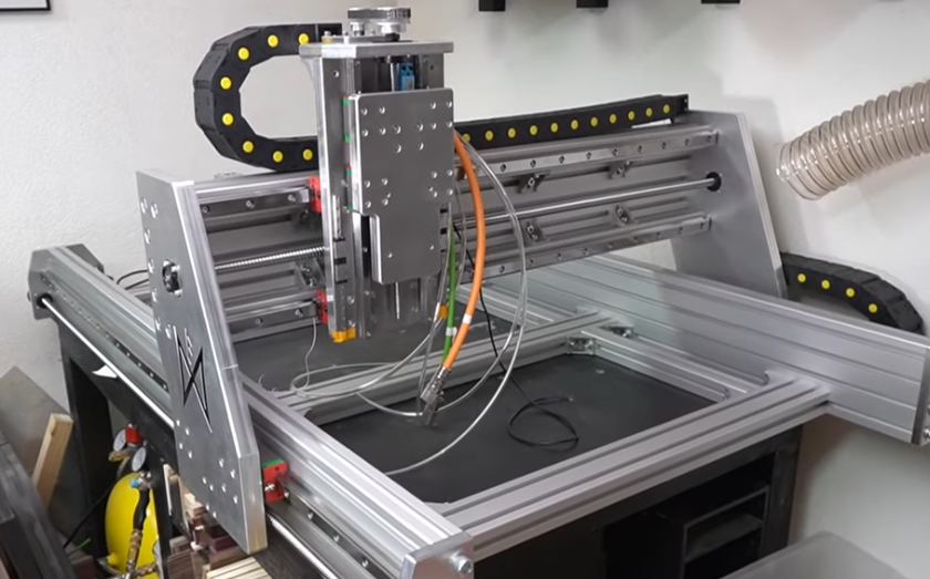
CNC (Computer Numerical Control) machines are complex systems that combine mechanical components, electronic hardware, and software to perform precise and repeatable machining operations. Understanding each main component and its function is essential for correct selection, operation, troubleshooting, and maintenance of CNC equipment.
Overall CNC Machine Architecture
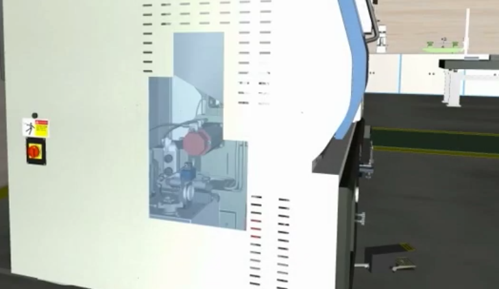
A CNC machine integrates three primary subsystems: the mechanical structure, the motion and spindle drives, and the computer-based control system. These subsystems are supported by tool handling, measurement and feedback devices, coolant and chip removal systems, and safety protections.
The mechanical structure provides rigidity and motion capability. Drives convert electrical energy into controlled movement of axes and spindle. The CNC controller interprets the part program (G-code), coordinates all axes and auxiliary functions, and supervises safety and diagnostics.
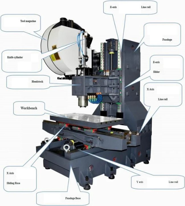
Base, Column, and Structural Frame
The base and column form the core mechanical frame of the CNC machine. Their main functions are to support all moving assemblies, absorb cutting forces, and maintain alignment over time.
Common structural elements include:
- Base (bed) – supports the table, saddle, and often houses chip conveyors and coolant tanks.
- Column – vertical support carrying the spindle head or cross beam.
- Cross rail / cross beam – on large gantry and bridge-type machines, supports the ram or spindle head.
- Headstock or spindle head – houses the spindle and drive components.
Frames are usually made from cast iron, welded steel, or mineral casting. The design focuses on high stiffness, vibration damping, and thermal stability to maintain CNC machining accuracy in heavy-duty or long-duration cutting.
Linear Axes, Slides, and Guideways
Linear axes allow controlled movement of the tool or workpiece in X, Y, and Z directions. Each axis consists of a slide system guided by precision ways.
Main elements include:
- Machine table or worktable – supports the workpiece and fixtures; typically moves in X and/or Y.
- Saddle – intermediate slide that supports the table or head and travels on guideways.
- Carriage or ram – carries the spindle or cutting head, often moving in Z or W axes.
Guideways provide accurate and repeatable paths for linear motion. Common types:
Box ways are large sliding surfaces with high load capacity and good damping, suited for heavy cutting. Linear rolling guideways use recirculating balls or rollers, offering lower friction and higher rapid traverse speeds, typically used in high-speed machining centers.
| Parameter | Typical Range | Functional Impact |
|---|---|---|
| Axis travel (X/Y/Z) | 200–2,000 mm (small to medium VMCs) | Defines maximum part size and fixture envelope |
| Rapid traverse speed | 20–60 m/min | Affects non-cutting time and productivity |
| Positioning accuracy | ±0.002–0.01 mm | Determines achievable dimensional tolerance |
| Repeatability | ±0.001–0.005 mm | Impacts consistency over multiple cycles |
Proper lubrication, slideway protection (telescopic covers, bellows), and correct preload settings are critical to maintaining axis accuracy and service life.
Ball Screws and Linear Drive Mechanisms
Ball screws convert rotary motion from the axis servo motors into linear motion of the slides. They have a threaded shaft and a nut filled with recirculating balls that greatly reduce friction compared to conventional screws.
Main functions and parameters:
Ball screw pitch determines the linear travel per revolution, affecting feed resolution and speed. Preload reduces backlash and increases stiffness. Leadscrew diameter and support bearings define load capacity and critical speed.
Alternatives to ball screws include linear motors in some high-speed machines, which directly drive the axis without mechanical contact, improving response and eliminating backlash, but requiring different design considerations in cooling and control.
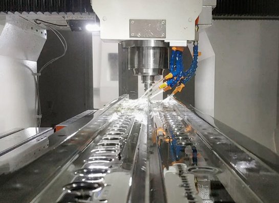
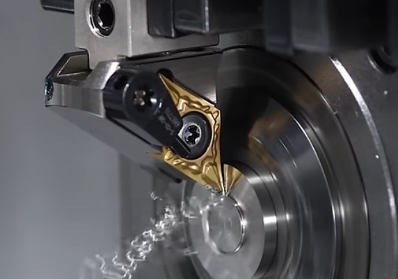
Spindle Assembly and Spindle Drive
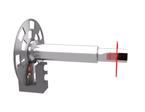
The spindle is the rotating component that holds and drives the cutting tool (or the workpiece in CNC lathes). Its assembly includes mechanical, electrical, and thermal management elements that strongly influence machining capability and surface finish.
Main spindle components:
- Spindle shaft – precision-ground shaft that provides tool interface and rotation.
- Spindle bearings – usually angular contact ball or roller bearings for high rigidity.
- Tool interface – taper or other connection standard such as BT, CAT, HSK, or ISO.
- Drawbar mechanism – clamps and releases the tool holder.
- Spindle motor and coupling – drive torque to the spindle.
The spindle drive can be belt-driven, gear-driven, or motorized (built-in) spindle. Motorized spindles integrate the motor inside the spindle body, allowing very high speeds with compact design and reduced inertia. Gear-driven spindles allow high torque at low speed, suitable for heavy milling and drilling of tough materials.
| Specification | Typical Value Range | Application Influence |
|---|---|---|
| Spindle speed range | 40–12,000 rpm (general-purpose machining centers) | Determines suitable tool diameters and materials |
| Spindle power | 7–40 kW | Affects allowable material removal rate |
| Maximum spindle torque | 50–300 Nm | Defines capability for heavy-duty cutting |
| Taper type | BT40, BT50, HSK63, etc. | Impacts rigidity, speed capability, and tool compatibility |
Spindle cooling (air, oil, or water) and thermal compensation functions in the CNC machine components are important for maintaining dimensional stability during long machining cycles.

Tool Holders, Tooling System, and ATC
The tool holding system connects the cutting tools to the spindle and allows automatic tool changes. Its design affects rigidity, balance at high speeds, and changeover time.
Main elements:
Tool holders and tool shanks (e.g., ER collet chucks, end mill holders, shell mill arbors) provide secure clamping of cutting tools. Pull studs or retention knobs attach to the holder and are gripped by the drawbar. The tool magazine (carousel, chain, or matrix type) stores multiple tools ready for automatic exchange.
The Automatic Tool Changer (ATC) mechanism transfers tools between spindle and magazine. Common types include arm-type ATCs that use a swing arm to exchange tools, and direct tool pick-up systems where the spindle moves to the tool position. Typical capacities range from 16 to over 120 tools, depending on machine size and complexity.
Accurate tool length and diameter management in the CNC control, along with tool life monitoring, are necessary to fully utilize the tooling system and prevent collisions or dimensional errors.
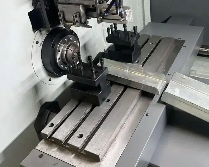
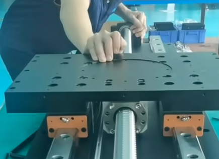
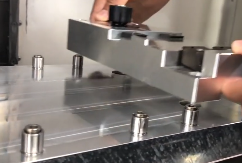
Workholding Devices and Fixtures
Workholding components secure the workpiece in a stable and repeatable position relative to the CNC machine axes. Effective workholding maximizes accessibility for tools, minimizes deformation, and ensures safety.
Common workholding devices include:
- Machine vises – for prismatic parts on machining centers.
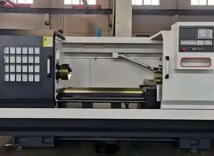
- Chucks – 3-jaw or 4-jaw chucks for lathes, and specialized chucks for round workpieces on mills.
- Fixtures and jigs – dedicated or modular systems to hold complex shapes, often designed for multi-part clamping.
- Pallets and zero-point clamping systems – for fast changeover and high repeatability in flexible manufacturing.
Workholding interacts closely with machine capacity; clamping force must be adequate to resist cutting forces while avoiding distortion. Fixture design must consider tool paths, coolant flow, chip evacuation, and accessibility for probing and measuring.
CNC Controller Hardware
The CNC controller is the central processing unit of the machine, responsible for interpreting programs, controlling motion, and managing all auxiliary functions.
Typical hardware modules:
Operator panel and display provide the human–machine interface (HMI) for program input, monitoring, and alarms. The main CPU unit executes real-time motion control algorithms and PLC logic. I/O modules connect sensors, switches, valves, and relays. Axis and spindle drive interfaces coordinate with servo amplifiers and spindle inverters.
Controller functionality includes G-code interpretation, coordinate transformations, interpolation of complex curves, tool offset application, and compensation for backlash and thermal error. Integrated PLC functions often handle coolant, doors, tool changers, and safety interlocks.
Servo Motors, Drives, and Motion Control
Servo motors and their drives (amplifiers) provide precise, closed-loop control of axis and spindle motion. They receive command signals from the CNC controller and adjust speed, position, and torque based on feedback devices.
Key components:
AC servo motors with high-resolution encoders are standard in modern machines, offering high dynamic response and accuracy. Servo drives convert command signals into appropriate voltage and current for the motors, perform current and speed loops, and provide diagnostics. Inverters or spindle drives control the spindle motor, enabling speed changes and orientation.
Motion control functions handle interpolation (coordinated movement of multiple axes), acceleration and deceleration profiles, jerk limitation, and contouring tolerance settings. These functions are essential for achieving smooth surfaces and maintaining tolerance in complex multi-axis machining.
Feedback Devices: Encoders, Scales, and Switches
Feedback devices measure the actual position, speed, and sometimes load of axes and spindle. They close the control loop and enable the controller to correct errors in real time.
Main feedback types:
- Rotary encoders – mounted on servo motors or screw ends; provide incremental or absolute position.
- Linear scales – mounted along the axis travel; directly measure table or slide position.
- Limit switches and reference switches – define travel limits and reference (home) positions.
High-resolution encoders and linear scales improve positioning accuracy and repeatability, especially in applications requiring tight tolerances and compensation for screw pitch errors or thermal expansion. Feedback parameters such as resolution (e.g., sub-micrometer), maximum counting frequency, and communication protocol (e.g., serial interfaces) are matched to the controller’s capabilities.
Coolant, Lubrication, and Chip Management Systems
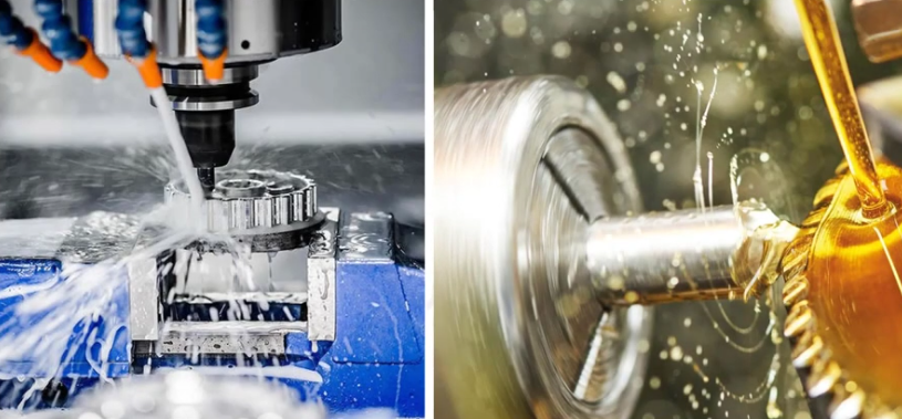
Coolant and lubrication systems support cutting performance and protect mechanical components, while chip management removes machining debris from the cutting area.
Coolant system functions:
Coolant pumps supply cutting fluid to the tool–workpiece interface to reduce temperature, improve chip evacuation, and extend tool life. Nozzles or through-spindle coolant channels deliver fluid directly to the cutting edge. Filtration and tank systems remove chips and contaminants from coolant, maintaining flow and preventing clogging.
Lubrication systems automatically distribute oil or grease to ball screws, guideways, and bearings. Centralized lubrication units use timed pumps and metering valves to ensure consistent lubricant delivery, preventing wear and reducing friction.
Chip management components include conveyors (belt, scraper, or screw type), chip augers, and chip bins or carts. Effective chip handling prevents accumulation around the tool and workpiece, reduces manual cleaning, and protects machine covers and seals from damage.
Electrical Cabinet and Power Distribution
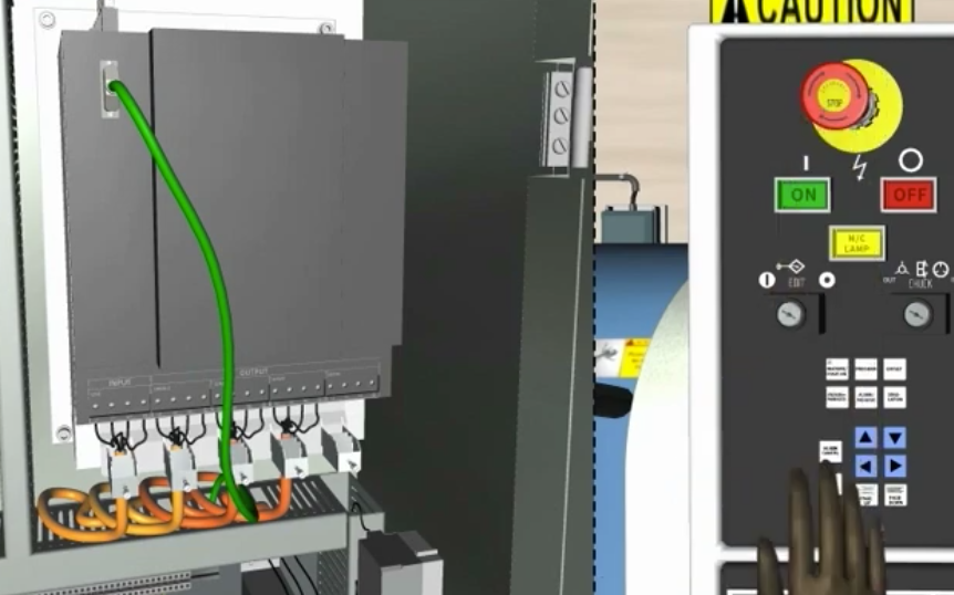
The electrical cabinet houses and protects all electrical and electronic components that supply and control power within the CNC machine.
Main contents and functions:
Power distribution units route incoming mains power to different machine subsystems through circuit breakers and contactors. Transformers and power supplies generate required voltages for control electronics, drives, and auxiliary devices. Servo drives, spindle inverters, and PLC modules are typically mounted within the cabinet with appropriate cooling and ventilation.
Cable management, grounding, and shielding are essential to reduce electromagnetic interference (EMI) that can affect encoder signals, communication buses, and sensor reliability. Proper labeling of terminals and wiring simplifies maintenance and troubleshooting.
Safety Devices and Guarding Systems
Safety components protect operators, maintenance staff, and the machine itself. CNC machines must comply with relevant safety standards and are designed with multiple layers of protection.
Key safety elements:
- Physical guards and enclosures – prevent access to moving parts and contain chips and coolant.
- Interlocked doors and covers – equipped with switches that stop machine motion when opened.
- Emergency stop (E-stop) buttons – immediately cut power to motion drives when pressed.
- Overtravel limits – limit switches or software limits prevent axes from exceeding safe travel ranges.
- Thermal and overload protections – monitor currents, temperatures, and faults in motors and drives.
These systems interface with the CNC and PLC, ensuring that unsafe conditions cause controlled stopping of the machine and generate clear alarms for the operator.
CNC Human–Machine Interface (HMI)
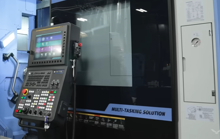
The human–machine interface provides access to all machine functions, enabling programming, setup, operation, and monitoring. A clear and logical HMI is important for efficient use of the CNC machine components.
Main HMI components:
Display screens show machine status, coordinates, program code, graphics, and diagnostics. Keyboards and keypads offer input for programming and commands. Soft keys and function keys provide context-dependent control actions. Handwheels and jog buttons allow manual axis movement during setup and measurement.
The HMI often includes modes such as automatic, MDI (manual data input), jog, and edit. It also provides interfaces for tool and work offset management, program management, alarm logs, and maintenance screens.
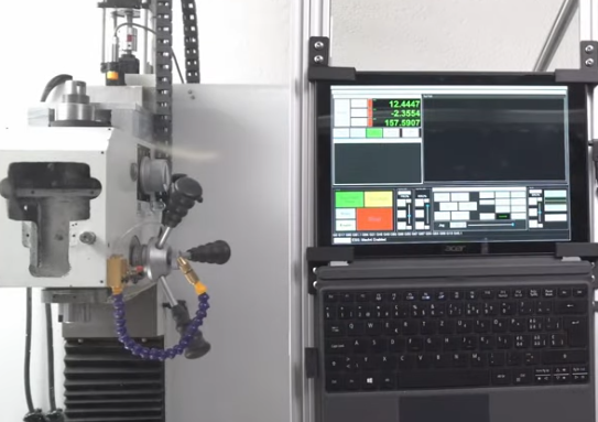
Measurement, Probing, and Calibration Devices
On-machine measurement devices and probing systems enhance accuracy and automation by checking workpiece dimensions and tool geometry directly inside the CNC machine.
Common devices include:
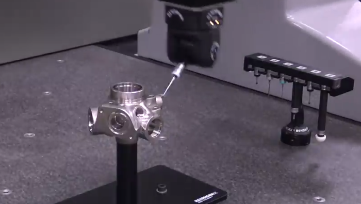
- Workpiece touch probes – measure part features, set work offsets, and verify part position.
- Tool length and diameter setters – automatically measure and update tool offsets.
- Laser tool measurement systems – non-contact measurement of rotating tools for precise length, diameter, and breakage detection.
These systems typically communicate with the CNC controller via macro programs and cycles, enabling automatic correction of offsets, detection of tool breakage, and reduction of manual inspection time.
Cable Carriers, Covers, and Protective Elements
Mechanical protection components ensure reliability and longevity by shielding sensitive parts from chips, coolant, and accidental damage.
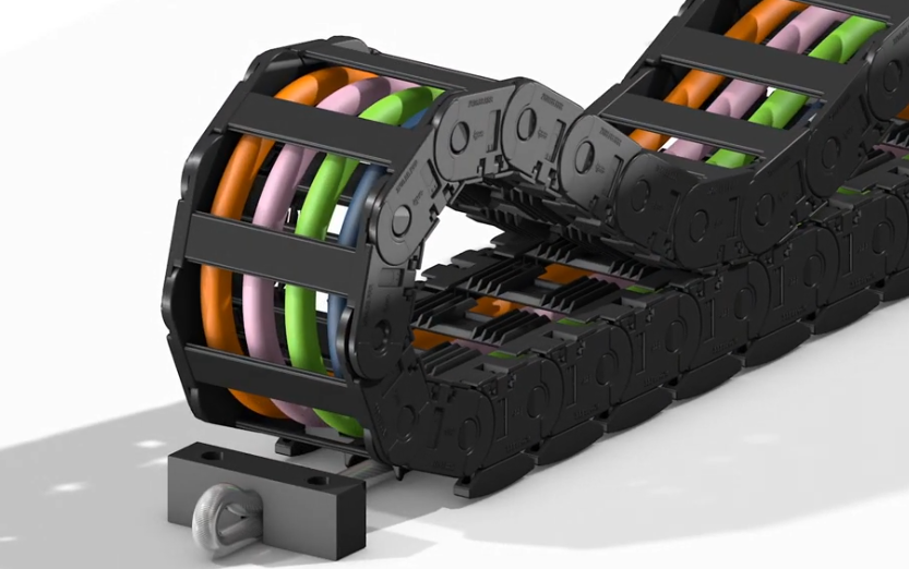
Accordion bellows and telescopic covers protect guideways and ball screws. Cable carriers route and protect power and signal cables for moving axes. Windows and viewing panels made from impact-resistant materials allow visual monitoring while maintaining safety.
Regular inspection and replacement of worn covers, seals, and cable carriers are essential to prevent coolant leakage, chip accumulation, and cable damage, which can lead to unplanned downtime.
Common Operational Considerations and Issues
While each CNC component has its dedicated function, practical operation and maintenance often reveal specific issues that affect overall performance and reliability.
Typical considerations include:
Alignment and geometry: Wear or accidental impacts can cause misalignment of guideways, spindle, and fixtures, resulting in taper errors, flatness issues, or poor surface finish. Periodic geometric inspection and correction help maintain accuracy.
Thermal effects: Spindle heat, drive heat, and ambient temperature changes can cause dimensional drift. Components such as spindle cooling systems, thermal compensation functions in the control, and stable shop environments reduce thermal error.
Contamination: Chips and coolant can damage seals, covers, and sliding surfaces if chip evacuation and protection are insufficient. Keeping the coolant system clean and ensuring all guards and covers function properly minimizes this risk.
Electrical noise and grounding: Encoder and communication signals can be disturbed by improper grounding or routing of cables near high-current lines. Correct cable separation, shielding, and grounding in the electrical cabinet and along cable paths preserve signal integrity.
FAQ about CNC Machine Components
What are the most critical CNC components for machining accuracy?
The most critical components affecting accuracy are the machine structure (base, column, and guideways), ball screws or linear drives, feedback devices such as encoders and linear scales, and the spindle assembly. Their stiffness, backlash, thermal behavior, and feedback resolution directly influence positioning accuracy, repeatability, and surface finish. Correct calibration, compensation settings, and maintenance of these components are essential for maintaining tight tolerances.
Which CNC machine components require the most regular maintenance?
Components that typically need the most regular maintenance are guideways and ball screws (cleaning and lubrication), coolant and chip management systems (coolant concentration, filter cleaning, and chip removal), spindle unit (monitoring bearings, vibration, and temperature), and protective covers and seals. Electrical components, such as cooling fans and filters in the electrical cabinet, also require periodic inspection to prevent overheating and dust accumulation.
