

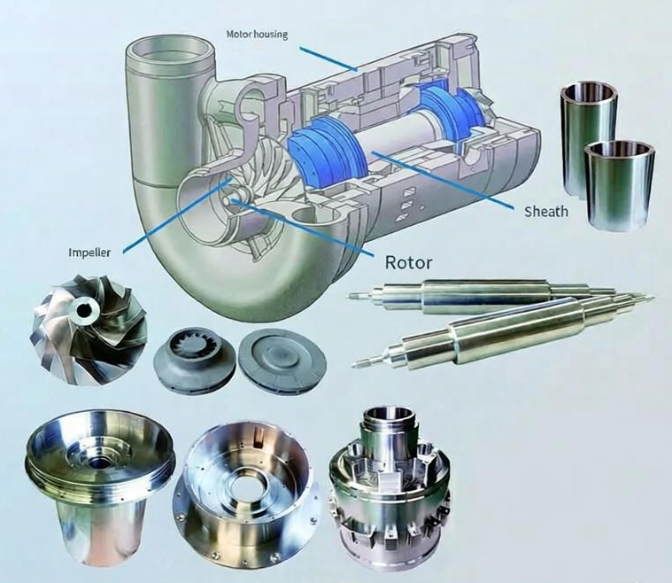
Impellers are critical rotating components used to transfer energy to fluids in pumps, compressors, blowers and turbines. Their performance depends heavily on the machining quality of blades, hubs and shrouds. This guide explains major impeller machining methods, common materials, dimensional requirements, typical cost drivers and practical ways to optimize manufacturability and cost.
Calculate Your Impeller Machining Cost
Impeller Machining Cost CalculatorNote: This is a rough estimate for CNC machining costs of a custom impeller (prototype/low volume). Actual costs vary significantly based on exact design complexity, tolerances, finishing, and shop location. Impellers often require 5-axis machining due to curved blades, leading to higher costs (typically $200–$2000+ per unit for prototypes). For accurate quotes, consult an impeller machining service supplier.
Impeller Types and Functional Requirements
Understanding impeller geometry and operating conditions is the foundation for selecting appropriate machining technologies and materials.
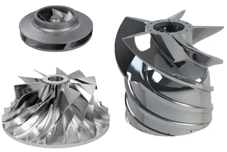
Common Impeller Types
- Centrifugal impellers: Radial or semi-radial blades, fluid enters axially and exits radially. Widely used in pumps and compressors.
- Axial-flow impellers: Propeller-like blades, fluid flows mainly along the rotational axis, used in fans and low-head pumps.
- Mixed-flow impellers: Intermediate between radial and axial, balancing head and flow rate.
- Open impellers: Blades on a hub without a front shroud, easier to machine but more sensitive to wear and clearance.
- Semi-open impellers: One shroud (usually rear), improved stiffness and efficiency with moderate machining complexity.
- Closed impellers: Front and back shrouds enclosing the blades, highest efficiency but most demanding to machine internally.
Key Functional Requirements
Regardless of type, impellers must satisfy several critical functional requirements:
- Hydraulic/aerodynamic performance: Blade geometry must match design profiles, angles and thickness to achieve required head, flow and efficiency.
- Mechanical integrity: Sufficient strength and fatigue resistance under centrifugal, thermal and fluid-induced loads.
- Dynamic balance: Mass distribution around the rotational axis must be tightly controlled to minimize vibration and bearing loads.
- Corrosion and erosion resistance: Especially for slurry, seawater, chemical and high-velocity gas applications.
- Dimensional stability: Maintenance of clearances with casing, wear rings and diffusers over operating temperature range.
These requirements directly influence material selection, machining sequence, tolerances and inspection procedures.
Impeller Machining Methods
Impeller machining is usually performed on near-net-shape castings, forgings or bar stock. The primary challenge lies in generating complex, twisted blade surfaces and tight internal clearances while maintaining dimensional accuracy and surface quality.
CNC Milling of Impellers
CNC milling is the most widely used method, especially for medium to high precision impellers. It can be applied to both blisks (integrally machined rotor and blades) and classic separate impellers.
3-Axis CNC Milling
3-axis milling is suitable for simpler geometries and open impellers.
- Typical applications: Small to medium open or semi-open impellers, axial fan impellers, simple radial blades.
- Operations: Face milling of shrouds, contour milling of simple blade profiles, drilling of hub and keyways.
- Limitations: Difficult to machine deep, twisted blade channels and closed impeller internal passages without extra setups or special fixtures.
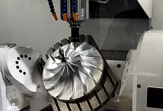
5-Axis CNC Milling
5-axis simultaneous milling is the standard for complex, high-performance impellers, particularly in compressors and turbochargers.
- Enhanced accessibility: Tool orientation can follow blade twist and reach deep channels with shorter tools.
- Reduced setups: Full blade passages and hub transitions can be machined in one or few setups, improving accuracy.
- Better surface quality: Continuous toolpath with optimized tool engagement reduces scallop height and tool marks.
- Precision: Suitable for tight tolerances (e.g., ±0.01–0.03 mm on critical profiles, depending on size and machine capability).
Typical operations include roughing of hub and shrouds, semi-finishing of blade passages and final finishing of pressure/suction surfaces.
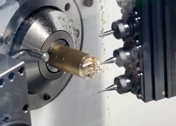
Multi-Axis Turning and Mill-Turn Machining
Many impellers have rotational symmetry in the hub and shroud regions. Multi-axis turning centers or mill-turn machines combine turning and milling in one setup.
- Turning operations: Rough and finish turning of hub diameters, shrouds, bores and flanges.
- Milling operations: Indexing or simultaneous 5-axis machining of blades, keyways and balance pads.
- Benefits: Reduced re-clamping, improved concentricity between hub and blades, shorter cycle times.
Electrical Discharge Machining (EDM)
EDM is used when mechanical cutting becomes difficult due to extremely hard materials or very tight internal geometries.
Wire EDM
Wire EDM is applicable primarily to thin, radial impellers or components with through-slots.
- Capabilities: Precise contouring of thin blades with small corner radii, minimal cutting force.
- Limitations: Slower than milling, requires conductive materials, unsuitable for thick 3D twisted blades.
Sinker EDM
Sinker EDM can form local features such as sharp root radii or relief pockets in hard materials.
It is often used as a supplementary process on high-hardness tool steels or special alloys after heat treatment.
Broaching, Slotting and Shaping
These methods are more common in older designs or when blade channels are relatively simple and radial.
- Broaching: Produces multiple blade slots in one linear stroke using a profiled broach tool.
- Shaping / slotting: Reciprocating cutting action to generate simple blade channels, often followed by grinding.
- Usages: Small pumps, low-cost impellers with repetitive radial slots.
Grinding and Superfinishing
Grinding is used to achieve tight tolerances and fine surface finish in specific regions.
- Applications: Seal surfaces, bearing fits, critical shroud faces, precise root fillets on high-speed impellers.
- Surface finish: Ra 0.2–0.8 µm is common for sealing and bearing contact surfaces.
- Superfinishing: For very high-speed turbomachinery requiring low roughness on blade leading edges and fillets.
Abrasive Flow Machining (AFM)
Abrasive flow machining pushes a viscoelastic abrasive medium through impeller passages.
- Purpose: Remove burrs, smooth flow channels, reduce roughness in areas difficult to access with conventional tools.
- Typical effect: Uniform deburring of blade trailing edges and internal corners, improvement of hydraulic efficiency.
Hybrid Machining Processes
In practice, impeller manufacturing often uses a combination of processes:
- Turning + 5-axis milling + AFM for high-performance closed centrifugal impellers.
- Forging + pre-turning + 5-axis milling for integral blisks.
- Casting + semi-finishing + grinding of critical seal surfaces.
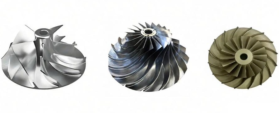
Impeller Materials and Machinability
Material choice is driven by operating environment, speed, fluid medium and cost constraints. Machinability varies widely and has direct impact on process selection, tool life and cost.
| Material Group | Typical Grades | Applications | Machinability Characteristics |
|---|---|---|---|
| Carbon & low-alloy steels | AISI 1045, 4140, 4340 | General industrial pumps, fans, low to medium pressure compressors | Good machinability, prone to rust, may require coating or plating |
| Stainless steels | 304, 316/316L, 410, 420, duplex grades | Chemical processing, food, seawater, corrosive fluids | Work hardening tends to occur, requires sharp tools and controlled cutting parameters |
| Nickel-based superalloys | Inconel 625, 718, Hastelloy C-276 | High temperature, high pressure gas compressors and turbines | Very poor machinability, low cutting speed, high tool wear, better with coated carbide or ceramics |
| Aluminum alloys | 6061-T6, 7075-T6, cast Al-Si alloys | Automotive turbochargers, low pressure blowers, lightweight fans | Excellent machinability, risk of built-up edge on tools, control of chip evacuation necessary |
| Titanium alloys | Ti-6Al-4V | Aerospace compressors and pumps requiring high specific strength | Low thermal conductivity, tendency to gall, moderate cutting speed and rigid tooling required |
| Bronze & copper alloys | CuSn, CuAl bronzes, nickel aluminum bronze | Marine propellers, seawater pumps | Good machinability, abrasive constituents in some bronzes may wear tools |
| Engineering plastics | PA, PEEK, PVDF | Corrosion-resistant and low-noise pumps for chemicals and water treatment | Easy cutting, need control of heat buildup and dimensional stability |
Influence of Material on Process Planning
Material selection affects:
- Cutting speed, feed and depth of cut.
- Tool material and coating (carbide, cermet, ceramic, PCD, CBN).
- Coolant type and flow rate (emulsion, high-pressure, MQL, cryogenic for some superalloys).
- Number of passes required to achieve final tolerance and finish.
For example, an aluminum impeller might be machined at cutting speeds over 400 m/min with high feed rates, while a nickel-based superalloy impeller might require cutting speeds under 60 m/min and multiple semi-finishing passes.
Heat Treatment and Its Impact
Many metallic impellers undergo heat treatment to optimize mechanical properties.
- Quenched and tempered steels: Machined after heat treatment to ensure dimensional stability, but with reduced machinability.
- Precipitation-hardened stainless steels and superalloys: Often rough-machined in the solution-annealed state and finish-machined after aging.
- Stress relieving: Applied between roughing and finishing to minimize distortion in thin blades.
Design Features Affecting Machining Complexity
Impeller geometry is a major cost driver. Designing for manufacturability can simplify machining while preserving hydraulic performance.
Blade Geometry
Blade shape, thickness and twist directly influence toolpath complexity and achievable tolerance.
- Blade count: Higher blade numbers increase machining time and toolpath lengths.
- Blade thickness: Very thin blades (e.g., <2–3 mm on medium-sized impellers) increase risk of vibration and deflection.
- Twist and curvature: More complex 3D shapes require more advanced CAM strategies and longer cycle times.
- Leading/trailing edge radius: Extremely sharp edges are difficult to machine and prone to damage during handling; a small radius often balances performance and manufacturability.
Hub and Shroud Geometry
Hub and shroud profiles affect both hydraulic performance and ease of clamping.
- Flat or simple conical shrouds are easier to turn and balance.
- Double-curved shrouds require extensive 5-axis milling.
- Thick shrouds improve stiffness during machining but increase weight and material cost.
Clearances and Passage Width
Narrow flow passages and deep channels present challenges:
- Limited tool diameter: Requires long, slender cutters and careful selection of step-over and step-down to avoid chatter.
- Chip evacuation: Especially in deep radial channels, insufficient chip removal raises temperature and tool wear.
- Inspection access: Tight passages complicate tactile measurement and may require optical or CT inspection.
Balance Features and Correction Areas
To enable dynamic balancing, many impeller designs incorporate local material pads or grooves.
- Balance pads on front or back shroud: Machined in advance and later removed partially for fine balancing.
- Grooves or pockets: Provide specific locations where material can be removed without affecting performance.
Typical Machining Process Flow for Impellers
While details vary by design and material, a typical workflow follows several main stages.
Pre-Machining Preparation
- Raw material preparation: Saw cutting bar or plate, cleaning castings or forgings, removing risers and gates.
- Initial inspection: Dimensional and visual checks to confirm material allowance and detect casting defects.
- Datum definition: Selection and marking of primary reference surfaces for all subsequent operations.
Rough Machining
Roughing removes the majority of excess material while leaving a defined allowance for finishing.
- Turning: Rough turning of hub, bore and shroud outer surfaces on lathes or mill-turn centers.
- Milling: 3-axis or 5-axis roughing of blade passages, hubs and shrouds using high-feed or trochoidal strategies.
- Typical allowances: 0.5–2.0 mm on blade surfaces and shrouds depending on impeller size and expected distortion.
Intermediate Heat Treatment (If Required)
For some steels and alloys, a stress relief or intermediate heat treatment may be used after roughing.
- Purpose: Reduce residual stresses induced by casting, forging and rough machining.
- Benefit: Lower risk of distortion during finishing, improved dimensional stability in service.
Semi-Finishing
Semi-finishing refines the geometry and equalizes stock allowance for final passes.
- Target: Uniform allowance on all functional surfaces, typically 0.2–0.6 mm.
- Approach: More conservative cutting parameters and optimized toolpaths following the near-final geometry.
Finishing
Finishing operations achieve the final dimensions, tolerances and surface finish requirements.
- Blade finishing: 5-axis scallop or swarf milling of pressure and suction surfaces, careful control of step-over.
- Shroud finishing: Face milling or turning to precise thickness and flatness, grinding when required.
- Bore and fit surfaces: Boring, reaming and grinding to specified tolerances.
Deburring and Flow Surface Smoothing
Residual burrs on blade edges and in internal corners can negatively affect hydraulic performance and may detach during operation.
- Manual deburring: Hand tools, rotary files and abrasive wheels for localized removal.
- AFM or abrasive blasting: For uniform treatment of entire passages and consistent surface texture.
- Typical surface roughness in flow passages: Ra 0.8–3.2 µm depending on application.
Balancing and Final Inspection
Final quality steps verify dimensional conformity and dynamic behavior.
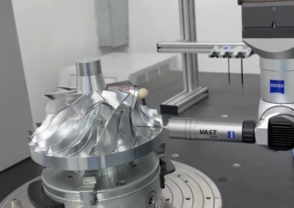
- Dimensional inspection: CMM, laser scanning or optical measurement of blade geometry, hub diameter, shroud thickness and bolt circle.
- Static balancing: Preliminary weight distribution adjustment before dynamic balancing.
- Dynamic balancing: Correction of residual unbalance at specified rotational speed and tolerance grade.
- Non-destructive testing (when required): Dye penetrant, magnetic particle or radiographic inspection to detect cracks or inclusions.
Tolerances and Surface Requirements in Impeller Machining
Impellers must satisfy multiple categories of tolerances, each affecting manufacturing complexity.
Geometric Tolerances
- Concentricity and runout: Hub bore to outer diameter or shroud reference, often 0.02–0.05 mm depending on size.
- Flatness of shrouds: Critical for sealing against casing or wear rings.
- Blade profile accuracy: Deviation from nominal 3D model, commonly in the range of ±0.03–0.2 mm.
- Clearance control: Tip clearance between impeller and casing components, typically a small fraction of the impeller diameter.
Dimensional Tolerances
Standard linear tolerances are applied to thicknesses, diameters and lengths.
- Hub bore diameters: Often H7 or tighter for press fits, looser tolerances for sliding fits.
- Keyways and splines: Tolerances defined by shaft standards; require accurate milling or broaching followed by inspection.
- Shroud thickness: Controlled to avoid mass imbalance and ensure structural stiffness.
Surface Roughness Requirements
Required surface roughness depends on functional role.
- Seal surfaces and bearing fits: Ra 0.2–0.8 µm achieved by turning and grinding.
- Flow surfaces: Ra 0.8–3.2 µm; smoother surfaces reduce friction but may increase cost.
- Non-functional surfaces: Ra 3.2–6.3 µm usually sufficient.
Cost Drivers in Impeller Machining
Machining cost is influenced by a combination of design, material and manufacturing factors. Understanding these drivers helps in setting realistic budgets and optimizing designs.
Material-Related Cost Drivers
- Raw material cost: High-performance alloys such as nickel-based superalloys and titanium are significantly more expensive than carbon steel or aluminum.
- Material removal volume: Thick hubs, wide shrouds and large stock allowances increase cutting time and tool wear.
- Machinability: Hard or work-hardening materials require slower cutting speeds, more expensive tooling and more frequent tool changes.
Geometry-Related Cost Drivers
- Complex 3D blades: High curvature and twist require long 5-axis toolpaths and careful CAM programming.
- Thin sections: Thin blades and shrouds may require multiple lighter passes and lower feeds to avoid deflection.
- Closed impeller passages: Internal machining increases tooling and setup complexity.
- Tolerance level: Tighter tolerances lead to smaller step-over, more passes and additional finishing operations such as grinding.
Process and Equipment Cost Drivers
- Machine type: 5-axis machining centers and high-end mill-turn machines have higher hourly rates than standard 3-axis mills or lathes.
- Tooling: Specialized cutters, form tools, high-pressure coolant systems and custom fixtures add to upfront cost.
- Programming and setup: Complex impellers demand significant CAM programming time and thorough setup verification.
- Inspection: Extensive CMM measurement, 3D scanning or NDT increases indirect quality costs.
Production Volume and Batch Size
- Small batches or one-off prototypes: Higher unit costs due to non-recurring engineering, programming and fixturing.
- Medium to large series: Setup and tooling costs are amortized; opportunities for process optimization and cycle time reduction.
Strategies to Control and Reduce Impeller Machining Costs
Cost control is often a balance between functional requirements and manufacturing efficiency. Systematic optimization can yield significant savings without sacrificing performance.
Design for Manufacturability (DFM)
- Avoid unnecessarily sharp internal corners; use realistic fillet radii compatible with standard tools.
- Use consistent blade thickness where hydraulically acceptable, to simplify toolpaths and maintain uniform stiffness.
- Provide suitable access for tools, including consideration of tool diameter and holder length.
- Standardize hub and connection interfaces where possible to reuse programs and fixtures.
Material Selection with Machinability in Mind
Selecting the most appropriate material, rather than the most conservative, can reduce machining time and tooling costs.
- Use corrosion-resistant steels or bronzes instead of superalloys where the operating environment permits.
- For high-volume applications, choose alloys with stable machinability and availability to avoid process fluctuations.
Process Optimization
- Combine operations on mill-turn or multi-tasking machines to reduce setups.
- Use high-efficiency roughing strategies (e.g., constant engagement milling) to reduce cycle time and tool wear.
- Implement standardized tool libraries and proven cutting parameters specific to each material.
- Apply in-process measurement to correct deviations early, avoiding scrap at the finishing stage.
Fixture and Clamping Design
- Support thin shrouds and blades adequately during machining to minimize vibration and deformation.
- Use repeatable locating surfaces and modular fixtures to reduce setup time.
- Consider clamping that mimics operational loading to improve dimensional consistency under running conditions.
Inspection Planning
- Define critical characteristics that directly affect performance and focus high-precision measurement there.
- Use optimized measurement routines and fixtures to reduce CMM cycle time.
- Combine inline and offline measurement where appropriate.
Typical Cost Structure and Reference Ranges
Actual costs vary widely by region, supplier, material and design complexity. However, understanding the relative contribution of cost elements helps guide decisions.
| Cost Element | Low-Complexity Impeller | High-Complexity Impeller | Notes |
|---|---|---|---|
| Raw material | 20–40% | 25–50% | Higher share for expensive alloys and large diameters |
| Machining time (machine + labor) | 30–50% | 35–55% | Main driver for complex 5-axis operations |
| Tooling and fixtures | 5–15% | 10–20% | Includes cutting tools, holders, special fixtures |
| Programming and engineering | 5–10% | 10–20% | Per-unit share decreases with higher batch size |
| Inspection and testing | 5–10% | 5–15% | Depends on level of CMM, NDT and balancing required |
| Overhead and margin | 10–20% | 10–20% | Administrative, facility and profit factors |
For small to medium impellers in standard materials, machining may range from relatively low cost per unit for simple open impellers to significantly higher cost for complex closed impellers in superalloys. Large-diameter or high-speed impellers with tight tolerances and extensive balancing requirements typically fall toward the higher end of cost ranges.
Impeller Machining Made Precise and Cost-Effective with XCM
At XCM, we specialize in high-precision impeller machining that balances performance, material choice, and cost efficiency. From aluminum and stainless steel to brass, copper, and engineering plastics, we help you select the right material for strength, durability, and weight requirements. Our expertise covers advanced machining methods including CNC milling, turning, and 5-axis operations, ensuring tight tolerances and flawless finishes for even the most complex impeller designs. By optimizing production processes and lead times, XCM reduces unit costs while maintaining top-tier quality. Partner with XCM to turn impeller machining into a competitive advantage for your products and accelerate your time to market.
FAQ: Impeller Machining
What is impeller machining?
Impeller machining is the process of precisely manufacturing or finishing impellers used in pumps, compressors, or fans. It includes turning, milling, grinding, and drilling to ensure the impeller meets design specifications and performance requirements.
What materials are commonly used for impellers?
Common impeller materials include stainless steel, aluminum alloys, titanium alloys, and nickel-based alloys. Material selection depends on operating conditions, corrosion resistance, and wear resistance requirements.
How is high precision ensured in impeller machining?
High precision is achieved through CNC machining, precise fixturing, tool compensation, inspection using coordinate measuring machines (CMM), and strict process control.
How is balancing achieved in impellers?
Impellers are dynamically balanced using specialized balancing machines to prevent vibrations during operation. Material is added or removed from the impeller hub or blades as needed.
How is impeller quality inspected after machining?
Quality is inspected using CMM measurement, surface roughness testers, visual inspection, and sometimes non-destructive testing (NDT) like ultrasonic or dye penetrant testing to detect cracks or defects.
