
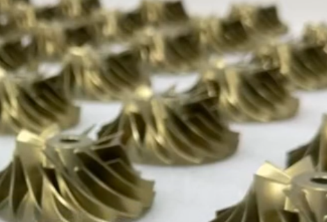
Impeller Fundamentals
An impeller is the core rotating element of many turbomachines such as pumps, fans, blowers, compressors and turbines. It transfers mechanical energy from the shaft to the working fluid, generating pressure rise and controlling flow rate. Understanding basic concepts is essential before addressing design, materials, and manufacturing.
What an Impeller Is
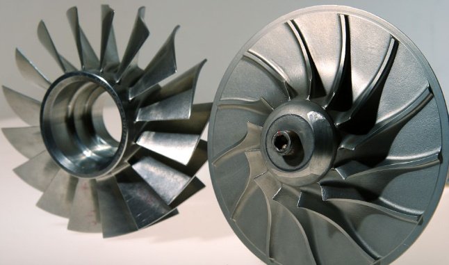
An impeller is a bladed rotor that rotates at a specified speed and imparts energy to a liquid or gas. Fluid flows through the blade passages and exits with higher energy, expressed as increased pressure, velocity or both. Impellers are typically classified by the direction of primary flow relative to the shaft axis:
- Centrifugal (radial) impellers: fluid enters near the axis and exits radially.
- Axial impellers: fluid flows mainly along the shaft axis.
- Mixed-flow impellers: fluid exits with both axial and radial components.
- Screw or helical impellers: fluid is transported by a helical channel, often with strong axial flow.
Each type has characteristic head–flow curves, efficiency ranges and structural features that drive different design and manufacturing requirements.
Main Functions and Application Areas
The primary functions of an impeller are:
- Energy transfer: convert shaft power into fluid energy.
- Pressurization: raise fluid pressure or head to a specified level.
- Flow control: deliver a required flow rate under given system resistance.
Typical application fields include:
Pump industry: water supply, HVAC, chemical process pumps, oil and gas, boiler feed pumps, slurry pumps.
Fans and blowers: ventilation fans, industrial blowers, cooling fans in power generation and electronics.
Compressors and turbochargers: air compressors, gas compressors, turbochargers, superchargers.
Turbo machinery: steam and gas turbines, expanders, power generation turbines.
Marine and aerospace: marine pump impellers, propulsion pump-jet impellers, aircraft engine compressors and turbines.
Differences from Conventional Rotors
Compared with ordinary rotors such as solid shafts or simple discs, impellers show the following distinctive characteristics:
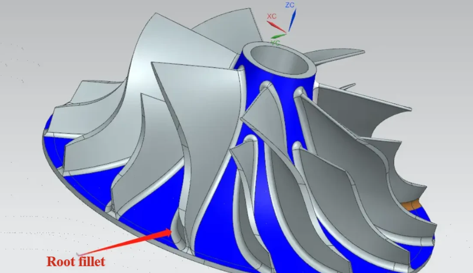
Complex geometry: twisted blades, 3D curved passages, variable thickness and fillets. The geometry strongly affects flow distribution and losses.
Fluid dynamic sensitivity: small deviations in blade angle, passage area or surface quality often cause measurable changes in head, efficiency and cavitation performance.
Higher precision requirements: tight tolerances on blade thickness, chord length, leading and trailing edge positions, and hub/eye diameters are needed to meet performance specifications.
Surface quality: surface roughness directly influences hydraulic and aerodynamic losses, noise and erosion behavior.
Balance and stability: rotating at high speed, impellers must meet strict static and dynamic balance tolerances to avoid vibration, bearing damage and fatigue.
Typical Products and Industries Suited to Impellers
Impeller-based solutions are suitable whenever continuous energy transfer to a fluid is required. Common examples include:
High-speed pump impellers: boiler feed pumps, high-pressure process pumps, multi-stage water injection pumps.
High-efficiency fan and blower impellers: backward-curved centrifugal fans, axial cooling fans, HVAC fans.
Gas turbine and turbocharger impellers: compressor wheels, turbine wheels, turboexpander impellers.
Special impellers: slurry pump impellers with wear-resistant features, non-clog sewage impellers, chemical pump impellers with corrosion-resistant geometry and materials.
Advantages and Limitations of Impeller-Based Solutions
Impeller technology offers several advantages:
High efficiency: optimized blade geometry can convert a large proportion of shaft power into useful fluid energy.
Customizability: geometry can be tailored to specific head, flow rate, speed, cavitation and noise requirements.
Compactness: high-speed operation enables high power density and compact equipment layouts.
However, there are inherent limitations and constraints:
Manufacturing complexity: 3D curved blades, thin walls and narrow passages increase machining and inspection difficulty.
Cost: high-precision casting, 5-axis machining, surface finishing and balancing raise production cost, especially for small batches.
Material and tolerance sensitivity: performance depends heavily on correct material selection, precise geometry and surface quality; deviations lead to performance drop or failure.
Impeller Materials and System Essentials
Material selection, design systems and understanding of structural composition are fundamental to reliable impeller performance. Manufacturing and measurement capabilities must be aligned with the chosen material and geometry.
Common Impeller Materials
Metallic materials are used when strength, temperature resistance and durability are critical, while non-metallic materials are used for corrosion resistance, weight reduction or cost control.
| Material Type | Typical Alloys | Main Features | Typical Uses |
|---|---|---|---|
| Stainless steel | CF8M, 316, 304, 17-4PH | Good corrosion resistance, acceptable strength, suitable for many fluids | Chemical pumps, process pumps, marine pumps |
| Aluminum alloy | AlSi, 6xxx, 7xxx | Low density, good machinability, good thermal conductivity | Fans, low to medium pressure compressors, lightweight systems |
| Copper alloy | Bronze, brass, nickel aluminum bronze | Good corrosion resistance in seawater, good wear resistance | Marine pumps, seawater applications, some slurry pumps |
| Cast iron | Gray iron, ductile iron | Good castability, high damping, economical | General water pumps, HVAC pumps, low-cost industrial pumps |
| Titanium alloy | Ti-6Al-4V and similar | High specific strength, excellent corrosion resistance, higher cost | Aerospace, high-end marine and chemical pumps, gas turbines |
| Engineering plastics | PPO, PPS, PVDF, PA, PEEK | Corrosion resistance, lightweight, suitable for moderate temperature and load | Low-speed pumps, small fans, chemical dosing pumps |
| Composite materials | Fiber-reinforced polymers | High stiffness-to-weight ratio, corrosion resistance, complex molding possible | Specialty fans, corrosive environments, lightweight rotating parts |
Design Systems and Software
Modern impeller design is strongly supported by CAD and CFD tools. They help create accurate 3D geometry, perform fluid dynamics analysis and verify structural integrity.
Typical software categories include:
CAD/3D modeling: SolidWorks, CATIA, NX, Creo. Used to create parametric impeller models, define blade profiles, hubs, shrouds and interfaces with shafts.
CFD tools: ANSYS CFX, ANSYS Fluent, SolidWorks Flow Simulation and other solvers are used to evaluate pressure distribution, velocity fields, recirculation zones, cavitation risk and overall efficiency.
Structural analysis: FEA tools (e.g., ANSYS Mechanical, Abaqus) evaluate stresses, deflection and fatigue life under combined centrifugal and hydraulic loads.
Impeller Structural Components
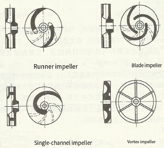
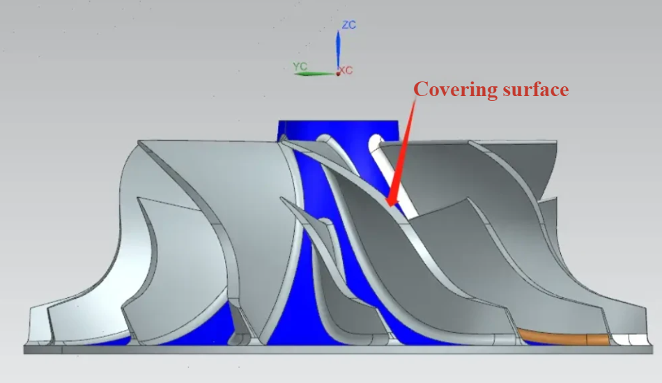
Although geometry varies widely, most impellers consist of the following elements:
Blades (vanes): form channels for fluid to flow. Their shape, angle and thickness distribution determine head, flow and efficiency.
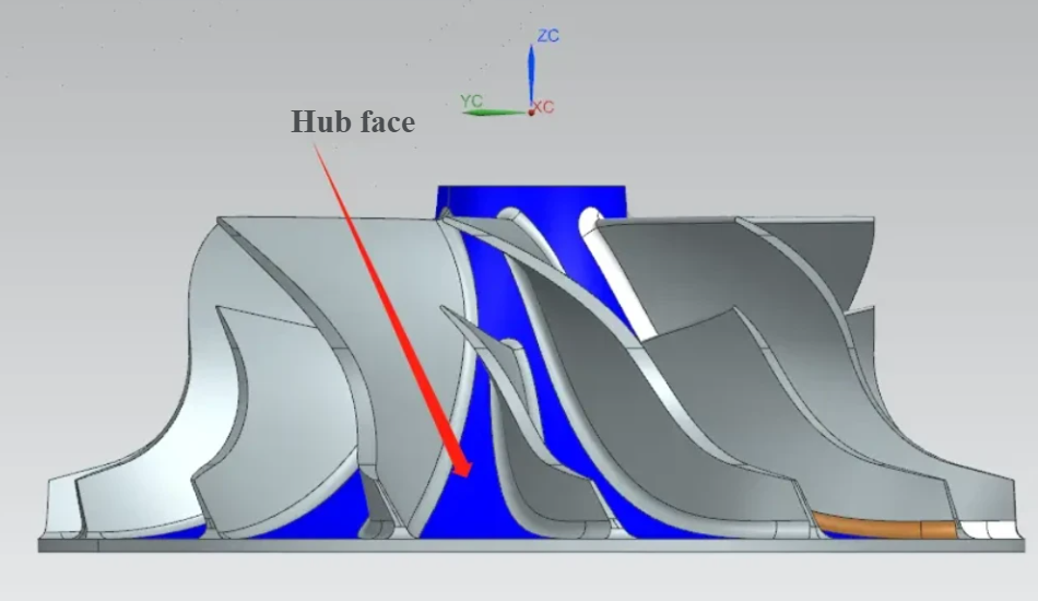
Hub: central body attached to the shaft; transmits torque and provides structural support to blades.
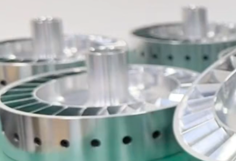
Shroud or cover plates: front and/or rear cover plates that close the blade passages, forming enclosed channels for centrifugal impellers. Open impellers may have no shroud at one side.
Rim or outer ring (for some designs): improves stiffness, reduces blade vibration and helps control leakage.
Basic Machining and Measurement Concepts
Accurate machining and measurement are required to achieve the designed flow passage geometry and balance requirements.
Processes often include:
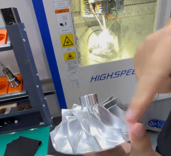
Precision casting: investment casting, lost-wax casting or sand casting to produce near-net shape blanks.
CNC machining: 3-axis or 5-axis milling and turning to achieve final geometry, including blade surfaces and critical diameters.
Surface treatment: grinding, polishing, honing or blasting to reach specified roughness and remove defects that affect flow or fatigue.
Measurement methods:
Conventional measuring tools: calipers, micrometers, gauges for critical diameters, thickness and runout.
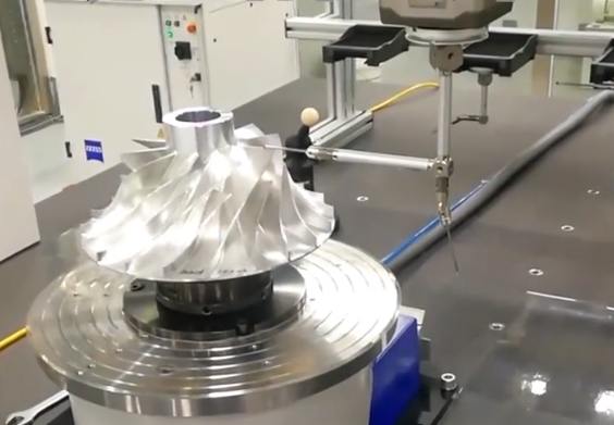
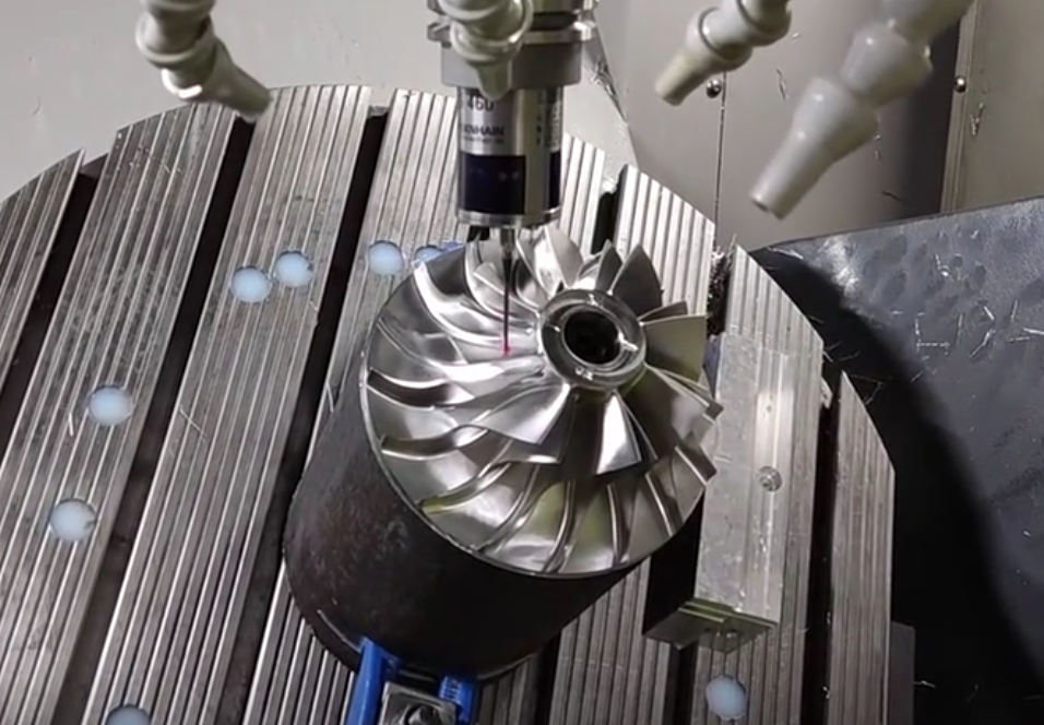
Coordinate Measuring Machine (CMM): provides accurate inspection of blade profiles, leading/trailing edge positions, hub concentricity and flatness of shrouds.
Key Performance and Stability Indicators
Impeller performance and operational stability are assessed by several geometric and dynamic parameters:
Balance: static and dynamic balancing quality must meet relevant standards to minimize vibration and bearing loads.
Blade angle accuracy: deviation from design inlet and outlet angles affects head, efficiency and cavitation behavior.
Concentricity: hub bore, outer diameter and reference surfaces must be concentric within specified tolerances.
Radial and axial stiffness: impellers must have sufficient stiffness to limit deformation and maintain clearance under operating load and speed.
Overview of Impeller Design and Manufacturing Flow
From initial performance requirements to delivered product, impeller design and manufacturing follow a structured process. Managing this flow reduces rework, improves consistency and shortens delivery times.
General Flow from Requirements to Finished Impeller
The typical sequence is:
Requirement definition: specify flow rate, head or pressure ratio, operating speed, fluid properties, allowable NPSH, efficiency targets and noise limits.
Preliminary design: select impeller type (centrifugal, axial, mixed-flow), choose specific speed range, estimate main dimensions such as diameter and width, and choose blade number and initial angles.
Numerical simulation: perform CFD analysis and, when necessary, structural analysis to validate and refine design parameters.
Manufacturing: generate manufacturing drawings and CAM programs, prepare tooling and produce impeller blanks and finished parts.
Inspection and testing: verify dimensions, balance and surface quality, then test hydraulic or aerodynamic performance.
Adjustment and release: if required, optimize geometry or process details, approve for production and deliver to customer.
Fluid Dynamic and Structural Design
Fluid dynamic design aims to meet specified head, flow and efficiency while controlling cavitation and noise. Structural design ensures sufficient strength, stiffness and life at operating conditions.
Key design steps include:
Determining main dimensions: calculate impeller inlet and outlet diameters, widths and hub diameters from hydraulic design formulas based on required flow and head.
Choosing blade number: balance between efficiency, cavitation performance and manufacturing feasibility. Too few blades can cause uneven flow and loss; too many can increase friction losses.
Setting blade angles: inlet and outlet angles are chosen to meet velocity triangle requirements and avoid separation or excessive incidence at design and off-design points.
Structural verification: evaluate stress from centrifugal forces, hydraulic pressure and temperature. Check safety margins against yield and fatigue limits.
Process Analysis and Manufacturing Planning
Before production, a process engineer evaluates the design from a manufacturability standpoint and defines a practical process route:
Blank production method: choose casting, forging or additive manufacturing depending on material, quantity, geometry complexity and cost constraints.
Machining strategy: define clamping schemes, reference surfaces, tool paths, roughing and finishing steps, and tools to handle thin walls and curved blades.
Surface treatment plan: specify polishing, coating or shot peening steps based on fatigue, corrosion and roughness requirements.
Impeller Manufacturing Steps
Typical steps from blank to finished impeller include:
Model preparation: prepare casting models or 3D printing data; generate CAM paths for machining operations.
Blank machining: rough machining of hub bore, basic diameters and reference surfaces for subsequent setups.
Finish machining: final machining of blades, shrouds, hub bore and key features, controlling final dimensions and surface roughness.
Testing and Performance Verification
After manufacturing, impeller quality is verified by mechanical and hydraulic tests:
Balance testing: static and dynamic balance tests correct mass distribution to meet balance grade requirements.
Hydraulic or aerodynamic performance testing: measure flow rate, head or pressure rise, efficiency, power consumption and operating range in a test loop or test rig.
Noise and vibration measurement: detect abnormal vibration levels, resonances or flow-induced noise that may indicate geometry or balance problems.
Quality Inspection and Shipment
Before shipment, the following checks are commonly performed:
Dimensional inspection: verify critical dimensions such as diameters, blade thickness, spacing, hub bore and keyway dimensions.
Dynamic balancing verification: confirm balancing results and record residual unbalance values.
Surface roughness and defect inspection: inspect for burrs, scratches, pores, cracks and coating defects; check required Ra values on blade surfaces and sealing regions.
Process and Material Selection
Material and process selection directly influence performance, reliability, cost and lead time. Matching material properties and manufacturing capabilities with the operating environment is essential.
Characteristics of Common Metallic Materials
Stainless steel: offers corrosion resistance for a wide variety of fluids and moderate to high strength. Widely used in chemical, food, water treatment and marine applications where hygiene or corrosion resistance is needed.
Aluminum alloys: provide excellent weight reduction and machinability. Suitable for fans, low-pressure compressors and applications where reduced rotating mass is desirable.
Copper alloys (bronze, nickel aluminum bronze): combine corrosion resistance in seawater with reasonable strength and erosion resistance. Common for marine pumps and applications with seawater or brine.
Cast iron: economical and suitable for general water and HVAC pumps where corrosion demands are moderate, and weight is not critical.
Use of Plastics and Composite Materials
Engineering plastics and composites are used primarily for low to moderate loads, corrosive fluids or when weight reduction is a priority.
Typical use cases:
Low-speed pumps and fans: plastic impellers reduce cost and eliminate rust issues in small water circulation pumps or household fans.
Chemical pumps: corrosion-resistant plastics or composites avoid the need for expensive metallic alloys for aggressive but low-pressure fluids.
Ventilation and exhaust systems: composite axial fans can be tailored for specific aerodynamic shapes and corrosion environments.
Material Machining Characteristics
Each material requires specific machining parameters and tool selections:
Wear resistance: hard or wear-resistant alloys may cause rapid tool wear and require suitable cutting tool materials and cooling.
Corrosion resistance: some stainless steels and nickel alloys tend to work-harden, demanding controlled cutting conditions.
Thermal expansion: differences in thermal expansion coefficients affect dimensional stability and must be considered in tolerance calculation for high-temperature operation.
Design for Manufacturability (DFM) for Impellers
DFM helps avoid unnecessary cost and reduce risk of defects. Important considerations include:
Uniform blade thickness: avoid abrupt thickness changes that are difficult to cast or machine and that cause stress concentrations.
Smooth blade curves: use continuous curvature without sudden kinks to improve flow and simplify machining tool paths.
Machinable hub shape: provide sufficient material and accessible surfaces for clamping and machining of the hub and bore.
Avoiding excessively thin walls: maintain minimum thickness compatible with casting and structural requirements.
Accuracy, Tolerances and Surface Quality Requirements
For impellers, geometrical accuracy and surface quality significantly affect hydraulic efficiency, noise and vibration:
Tolerances on diameters and blade angles: ensure operating point matches design predictions and reduce performance spread between units.
Blade thickness and spacing: control flow passage area and distribution, affecting head and efficiency.
Surface roughness: smoother surfaces on blade pressure and suction sides reduce friction losses, limit boundary layer separation and lower noise.
Fundamentals of Impeller Design and Simulation
Modern design relies heavily on CFD for predicting flow behavior within impellers. Combined with robust geometric parameterization, it enables systematic optimization of performance and operating range.
Basic CFD Concepts for Impellers
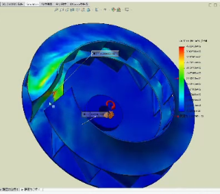
CFD analysis discretizes the flow domain into a mesh and solves the governing equations of fluid flow, typically Navier–Stokes equations with appropriate turbulence models.
Key CFD outputs used for impeller design include:
Pressure distribution: pressure rise from inlet to outlet, distribution on blade surfaces and in the volute or diffuser.
Velocity fields: local velocity magnitude and direction, secondary flows, separation zones and recirculation regions.
Loss estimation: head loss in blade passages, leakage paths and diffusers, used to estimate overall efficiency.
Common Analysis Tools
Design teams use specialized software to perform analysis and optimization:
ANSYS CFX: commonly used in turbomachinery for rotating machinery simulations with multiple frames of reference and detailed post-processing.
ANSYS Fluent: a general-purpose CFD solver with a wide range of turbulence and multiphase models, applicable to impellers in complex systems.
SolidWorks Flow Simulation: integrated with CAD, suitable for design iterations where quick insights are needed in early stages.
Coordinate Systems and Blade Parameters
Impeller geometry is usually defined in cylindrical or spherical coordinates and then expressed as 3D surfaces in the CAD environment. Important blade parameters include:
Blade camber and bending angles: describe how the blade curves from inlet to outlet and determine flow turning.
Leading and trailing edge thickness: must be sufficient for structural integrity yet thin enough to minimize losses and cavitation inception.
Helix or wrap angle: the circumferential extent of the blade, affecting flow guidance and diffusion.
Differences Among Axial, Centrifugal and Mixed-Flow Designs
Axial impellers: primarily accelerate fluid along the axis. They typically operate with lower pressure rise per stage but high flow rates and relatively low diameters compared to centrifugal designs.
Centrifugal impellers: convert tangential velocity into pressure as fluid moves radially outward. They provide higher pressure rise per stage and are common in many pump and compressor applications.
Mixed-flow impellers: combine axial and radial components. They are used when intermediate characteristics between pure axial and pure radial are desired, often providing compact designs with moderate to high pressure rise.
Simulation and Optimization Workflow
The typical simulation-driven workflow is:
Initial design: establish a baseline geometry using analytical or empirical methods.
Numerical simulation: run CFD to quantify performance across the operating range, including design and off-design points.
Design refinement: adjust blade angles, chord distribution, hub/shroud shapes and clearances to improve head, efficiency and cavitation margin.
Validation: confirm final design with additional simulations and, where necessary, prototype testing.
Impeller Assembly and Fixation Methods
Impeller performance depends not only on its intrinsic geometry but also on how it is mounted and aligned on the shaft and within the casing. Adequate assembly methods minimize runout, misalignment and vibration.
Assembly Principles
The following principles guide impeller assembly:
Axial positioning: the impeller must be located correctly relative to casing, diffusers or guide vanes to maintain designed clearances and flow passages.
Radial fixation: concentricity between impeller and shaft is critical to reduce imbalance and interference with stationary parts.
Blade balance: any mass eccentricity must be corrected by balancing procedures after assembly onto the hub or shaft.
Common Impeller Fixing Methods
The main fixation methods are:
Keyed connection: hub bore and shaft include keyway and key, transmitting torque and maintaining angular position.
Threaded connection: threaded hubs, nuts or locknuts secure impeller onto a threaded shaft end, often combined with locking devices.
Shrink or press fit: interference fit between hub bore and shaft ensures torque transmission without keys; requires precise control of tolerances.
Clamping sleeves or compression couplings: use tapered sleeves or clamping elements to transmit torque and enable easier disassembly.
Assembly of Multi-Stage and Compound Impellers
Multi-stage pumps and compressors use several impellers mounted in series on one shaft. When assembling multi-stage or compound impeller arrangements:
Axial spacing and clearances must be controlled to maintain designed inter-stage flow passages.
Cumulative concentricity and straightness of shaft and all impellers must be maintained to avoid excessive vibration.
Intermediate sleeves, spacers and keys must be machined and assembled to consistent tolerances.
Methods to Reduce Assembly Errors
To minimize misalignment and tolerance stack-up:
Precision fixtures: use dedicated fixtures and assembly jigs to control orientation and position during tightening.
Locating pins and reference surfaces: defined datum surfaces and dowel pins ensure repeatable positioning of shrouds, hubs and other components.
Controlled fits: specify and measure fit tolerances for bores, shafts and keys to avoid excessive play or interference.
Influence of Assembly on Performance and Efficiency
Poor assembly can cause increased vibration, noise and efficiency losses. Typical consequences include:
Increased radial and axial runout, leading to flow asymmetry and localized clearance variations.
Higher leakage through increased clearances, reducing effective head and efficiency.
Increased mechanical losses and heat generation in bearings and seals.
Impeller Manufacturing and Surface Treatment
Manufacturing technologies and surface treatments must be chosen to achieve specified geometry, surface quality, and mechanical properties while controlling cost.
Manufacturing Methods
Precision casting: investment casting and similar techniques allow complex shapes and fine details. Suitable for stainless steel, bronze and some high-performance alloys.
Forging: provides dense material structure and high strength, suitable for highly loaded impellers, often followed by extensive machining.
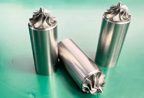
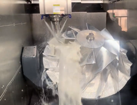
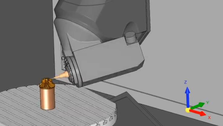
CNC machining: 3-axis and 5-axis machining is used to shape blades, hubs and shrouds accurately. For complex 3D blades, multi-axis machining is typically required.
3D printing / additive manufacturing: used for prototypes or complex geometries in specific metals and polymers. Allows internal channels and shapes that are difficult or impossible to cast.
Heat Treatment and Surface Treatment
Heat treatments adjust mechanical properties such as hardness, strength and toughness:
Quenching and tempering or solution and aging: used for steels and precipitation-hardened alloys to reach required strength.
Stress relieving: reduces residual stresses from casting or machining to reduce distortion during operation.
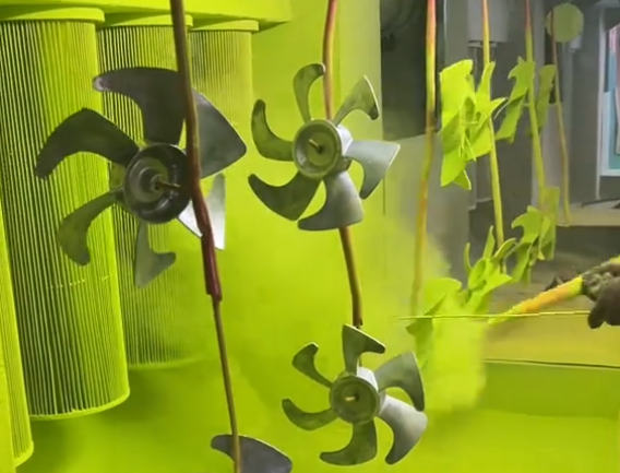
Surface treatments are applied to improve fatigue life, corrosion resistance or wear resistance:
Shot peening: introduces compressive residual stress on the surface, increasing fatigue strength.
Anodizing: often applied to aluminum impellers to enhance corrosion resistance and surface hardness.
Coatings and platings: may include hard coatings, corrosion-resistant layers or special functional coatings.
Cutting and Machining Parameters
Because impeller blades often have thin sections and complex curvature, machining parameters must be tuned to avoid distortion and surface defects:
Cutting force control: use appropriate feed, speed and tool geometry to avoid blade bending and chatter.
Temperature control: use cutting fluids, optimized chip thickness and tool materials to prevent heat buildup, work hardening or surface burns.
Step-over and depth of cut: in finishing passes, small step-over and shallow depth of cut help achieve the desired surface roughness and dimensional accuracy.
Material-Specific Manufacturing Considerations
Stainless steel: tends to work-harden; requires sharp tools, sufficient lubrication and controlled cutting speeds. Tool wear and heat generation must be monitored.
Aluminum alloys: easily machined but prone to burr formation. Requires appropriate cutting edges and deburring processes to prevent sharp edges or flow-disturbing burrs on blades.
Copper alloys: good machinability but may smear; cutting fluids and tool geometries must be selected to maintain clean edges and surfaces.
Balancing and Dynamic Balance Correction
High-speed impellers must undergo dynamic balancing to meet specified residual unbalance levels. The process typically includes:
Initial measurement: detect magnitude and phase of unbalance on a balancing machine at a given speed.
Correction: remove or add material at specified locations, often on balancing pads or designated correction areas on the hub or shrouds.
Verification: repeat measurements until residual unbalance is within tolerance.
Lubrication and Cooling During Manufacturing and Operation
During machining, appropriate lubrication and cooling reduce tool wear, heat-induced deformation and surface damage.
In operation, lubrication is typically related to bearings and seals, but for some high-speed or high-temperature impellers, cooling flows or specific surface treatments are used to reduce thermal loads and maintain dimensional stability.
Performance and Accuracy Control
Maintaining specified dimensions, surface quality and dynamic properties is essential to achieving consistent performance and long service life across batches.
Dimensional Accuracy and Geometric Tolerances
Key tolerances include:
Blade thickness: must be controlled along the blade height to maintain designed flow area and strength.
Blade spacing: influences channel width and flow distribution; excessive variation can cause unequal load on blades.
Hub and outer diameters: affect tip clearances and coupling with casing or diffuser parts.
Geometric tolerances: concentricity, circular runout, flatness and perpendicularity are specified to control alignment and balance.
Effects of Surface Roughness
Surface roughness is a significant factor in hydraulic and aerodynamic efficiency:
High roughness on blade surfaces increases friction and energy losses, reducing efficiency and potentially increasing noise and vibration.
Excessively smooth surfaces may be unnecessary and increase cost; roughness requirements must be balanced against performance needs.
Multiple Finishing Operations and Stock Allowance Control
Complex impellers often require multiple machining and finishing operations:
Stock allowance planning: sufficient allowance must be left for finishing, but excessive allowance increases machining time and risk of distortion.
Progressive finishing: rough machining, semi-finishing and finishing steps help control deformation and achieve final tolerances.
Control of Thermal Deformation and Vibration
Thermal effects and vibration can degrade shape accuracy and long-term stability:
Thermal deformation: must be considered during operation, especially for high-temperature or high-speed impellers. Material selection and geometry design help limit thermal growth.
Vibration control: avoiding resonance frequencies of blades and overall impeller assembly is critical. Structural analysis can identify natural frequencies and guide design modifications.
Defects and Repair
Common defects include burrs, porosity and cracks:
Burrs: arise from machining and can disturb flow or initiate cracks. They require controlled deburring methods that do not alter blade geometry.
Porosity: originates from casting and may reduce strength or cause leakage. Severity determines whether local repair or part rejection is required.
Cracks: critically affect structural integrity. Depending on size and location, repair may be possible by welding and re-machining, or the part may need to be scrapped.
Automation and Efficient Production
Automation of machining, inspection and balancing steps supports consistent quality and cost-effective production for both small and large batch sizes.
Multi-Stage Impellers and Combined Machining
Combining the machining of multiple impellers, or machining multi-stage structures as a single piece where feasible, can:
Reduce assembly errors by eliminating multiple interfaces.
Improve concentricity and alignment between stages.
Simplify balancing and reduce cumulative tolerances.
Precision Machining and Automated Assembly
Precision machining centers and automated assembly solutions help maintain geometric accuracy and batch consistency:
5-axis machining centers: allow accurate machining of complex blade shapes and hubs in fewer setups.
Automated assembly systems: can control torque, position and alignment during installation of impellers on shafts and within housings.
Dynamic Balancing and Online Inspection
Real-time or integrated inspection systems reduce scrap and rework by detecting deviations early:
Thickness and profile measurement: non-contact systems can measure blade thickness and profiles during or after machining.
Concentricity and spacing inspection: online gauging can verify hub bore position, outer diameter and blade spacing before final finishing.
Flexible Manufacturing and Batch Strategies
Production strategies depend on batch size and product diversity:
Small batches and multiple variants: benefit from modular design, standardized interfaces and easily adjustable machining programs.
Large batches of similar impellers: allow standardization of tools, fixtures and processes, enabling optimized cycle times and stable quality.
Efficient Production Management
Effective planning and control cover:
Process optimization: continuous improvement of feed rates, tool paths and fixture designs to reduce cycle time.
Material logistics: planning material procurement, storage and transport to avoid delays and maintain traceability.
Production scheduling: coordinating casting, machining, heat treatment and inspection steps to meet delivery deadlines.

Impeller Performance Testing and Control
Performance testing verifies that impellers meet design specifications under controlled conditions. Proper testing protocols and measurement methods are necessary for reliable evaluation.
Conventional Dimensional Inspection
Basic measuring tools used for impellers include:
Calipers and micrometers: measure diameters, thicknesses and lengths with targeted accuracy.
Thickness gauges: verify blade thickness at specified locations along the height and chord.
Thread gauges: inspect threaded connections on hubs or shafts for correct pitch and fit.
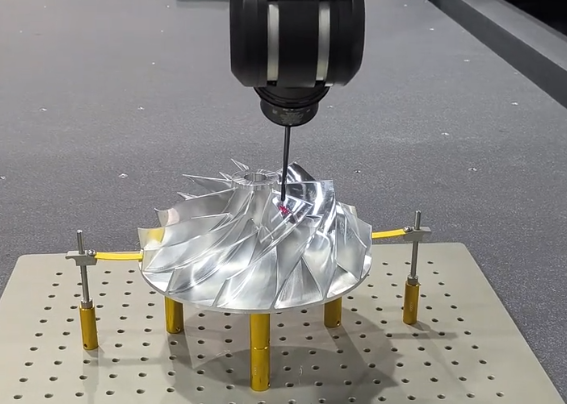
CMM and Contour Scanning
Coordinate Measuring Machines and scanning devices are used to inspect complex geometries:
Blade profiles: coordinates along blade surfaces are measured and compared to CAD models.
Thickness distribution: measurement across the blade height and chord verifies machining accuracy.
Concentricity and runout: CMM or dedicated gauges can confirm hub bore alignment and outer diameter concentricity.
First Article Inspection and Process Control
For new or modified designs, first article inspection ensures that manufacturing processes produce parts matching design requirements:
Dimensional layout: comprehensive measurement of all critical dimensions and tolerances.
Process capability analysis: assessment of variation to determine whether production can reliably meet tolerances.
Ongoing process control: sampling and monitoring of key dimensions to detect drift and intervene before out-of-tolerance parts are produced.
Fluid Performance Testing
Hydraulic or aerodynamic performance is typically tested on dedicated rigs:
Flow rate: measured with flow meters under controlled inlet and outlet conditions.
Head or pressure rise: determined from pressure differences upstream and downstream of the impeller.
Efficiency: calculated from measured torque or power input and fluid power output.
Noise and vibration: measured using microphones and vibration sensors to evaluate compliance with acoustic and mechanical specifications.
Nonconforming Product Analysis and Corrective Measures
When impellers fail to meet specifications, systematic analysis is necessary:
Porosity and cracking: requires casting analysis, evaluation of gating and riser designs, and possible adjustment of pouring and cooling processes.
Blade warping or distortion: may indicate insufficient fixturing, residual stresses or inappropriate heat treatment parameters.
Dimensional deviations: root causes may include tool wear, incorrect offsets, misaligned fixtures or inadequate process control.
Cost, Lead Time and Project Management
Successful impeller projects require control of cost, schedule and technical risk. Understanding cost components and how design decisions influence them supports better planning.
Cost Structure
The total cost of an impeller typically includes:
Material cost: depends on alloy, size, density, material utilization and scrap rate.
Machining cost: determined by cycle time, equipment type, tool cost and complexity of operations.
Inspection and testing cost: includes dimensional inspection, balancing and performance testing time and equipment usage.
Heat treatment and surface treatment cost: varies with type and duration of treatment and whether outsourcing is required.
Project Quotation and Evaluation
When preparing quotations and evaluating projects, the following factors are considered:
Material type and price level.
Geometry complexity, including blade shape, thickness and required tolerances.
Required batch size and expected repeat orders.
Performance and lifetime requirements, which may mandate more expensive materials, tighter tolerances or more extensive testing.
Processing Cycle and Delivery Planning
A typical schedule includes the following stages:
Tooling and mold preparation: design and fabrication of casting molds or special fixtures.
Blank production: casting or forging lead times, including cooling and preliminary inspection.
Machining and finishing: NC programming, roughing and finishing, deburring and surface treatment steps.
Inspection and delivery: dimensional inspection, balancing, packaging and shipping.
Methods to Reduce Rework
Reducing rework improves cost efficiency and lead time adherence:
Use of simulation: validate hydraulic and structural behavior before committing to tooling and production.
Accurate casting: near-net shape casting reduces the risk of insufficient material in critical areas and minimizes machining correction needs.
Controlled assembly and balancing: standardized procedures reduce the risk of misalignment and imbalance leading to rework.
Communication of Drawings and Performance Requirements
Clear communication with customers is essential for successful projects:
Functional requirements: flow rate, head, efficiency, allowable NPSH, noise limits and expected service life.
Drawings and 3D models: must define all critical dimensions, tolerances, surface finishes and reference datums.
Test and acceptance criteria: specify test conditions, permissible deviations and documentation requirements.
Safety Standards and Equipment Maintenance
Impeller manufacturing and testing involve rotating machinery, heavy lifting and high temperatures. Compliance with safety standards and planned maintenance ensures stable quality and safe operation.
Safety Procedures in Manufacturing
High-speed rotating equipment, heavy castings and hot heat treatment operations require strict safety rules:
Machine guarding and interlocks: protect operators from moving parts of CNC machines, grinders and balancing machines.
Lifting and handling: proper lifting accessories and procedures for moving heavy impeller blanks and assemblies.
Personal protective equipment: appropriate eye, ear, hand and heat protection for cutting, grinding and heat treatment areas.
Daily Inspection and Maintenance of Equipment
Daily checks maintain machine accuracy and reliability:
CNC machines and grinders: verify lubrication levels, check for abnormal noises or vibrations, and confirm critical positioning accuracy where applicable.
Balancing machines: inspect supports, sensors and safety guards, and perform periodic calibration.
Measuring equipment: verify that CMMs, gauges and micrometers are within calibration validity.
Preventive Maintenance and Fault Diagnosis
Planned maintenance avoids unplanned downtime and quality issues:
Regular inspection: check spindle runout, axis backlash and thermal behavior of machine tools.
Vibration and temperature monitoring: detect early signs of bearing wear, misalignment or structural issues in machines.
Corrective actions: schedule repairs, component replacements and alignments based on detected trends.
Environmental Protection and Waste Handling
Impeller production generates casting residues, cutting fluids, chips and grinding dust:
Handling of casting waste: solid waste must be disposed of or recycled according to regulations.
Cutting fluids: require proper collection, filtering and disposal or recycling.
Dust and particulate control: grinding and blasting operations need extraction and filtration to protect workers and the environment.
Extending Impeller Service Life and Maintaining Accuracy
In service, the following measures help maintain impeller integrity and performance:
Periodic dynamic balancing checks for high-speed units to compensate for wear or deposition on blades.
Surface inspection and cleaning to remove deposits or corrosion products that alter blade geometry.
Careful disassembly and assembly procedures to avoid introducing damage to blades, hub bores or keyways.
Common Issues and Case-Based Considerations
Despite careful design and production control, issues may still arise. Systematic analysis and feedback into design and process planning are required to achieve stable series production.
Diagnosis When Performance Does Not Meet Design
When measured head, flow or efficiency does not meet design values, potential causes include:
Flow passage design: insufficient or excessive diffusion, poor inlet or outlet geometry, or inadequate blade camber.
Blade thickness errors: increased thickness reduces flow area and changes velocity distribution.
Poor balancing or assembly: misalignment and vibration can alter effective clearances and cause additional losses.
Handling Cracks or Porosity
Cracks and porosity must be evaluated for structural impact:
Casting process adjustment: change of gating, risers, pouring temperature or alloy treatment may reduce porosity and shrinkage defects.
Repair: localized weld repair and re-machining may be possible for non-critical regions if allowed by applicable standards and customer specifications.
Scrap decision: critical cracks in high-stress regions usually require rejection of the part.
Improving Surface Finish When Out of Specification
When surface roughness does not meet requirements:
Adjust casting parameters or mold materials to reduce surface defects on as-cast surfaces.
Refine machining strategies, including cutting tools, feeds and speeds, to improve surface finish.
Implement appropriate polishing or finishing operations, especially in areas with high relative fluid velocity.
Analysis of Abnormal Vibration and Noise
Abnormal vibration and noise are often linked to:
Unbalance: inadequate dynamic balancing or mass changes due to wear or deposits.
Blade deformation: warping or cracking can cause uneven loading and flow disturbances.
Shaft and bearing issues: misalignment, bearing wear or improper installation can amplify vibration.
Case-Based Process from Design to Stable Production
A typical real-world progression from initial design to stable mass production involves:
Initial design and simulation: define impeller geometry for target head and flow; validate with CFD and structural analysis.
Prototype manufacturing and testing: produce initial prototypes, perform dimensional inspection, balancing and performance tests.
Issue analysis: identify discrepancies between measured and predicted performance, investigate quality or process-related causes.
Design and process updates: adjust geometry, tolerances, casting or machining processes based on test results.
Validation and ramp-up: verify improvements with additional units, then move to controlled series production with documented processes and inspection plans.
FAQ
What is an impeller?
An impeller is a rotating component of pumps, compressors, or turbines that transfers energy from the motor to the fluid, increasing its pressure and flow.
What are the main types of impellers?
The main types include open, semi-open, and closed impellers. Each type has different blade structures suited for specific fluid handling and performance requirements.
Why is impeller balancing important?
Proper balancing prevents vibrations, reduces wear, and extends the lifespan of both the impeller and the pump. Dynamic balancing is typically performed after machining.
What materials are impellers made from?
Common materials include stainless steel, aluminum alloys, bronze, titanium alloys, and high-performance plastics. Material choice depends on fluid type, temperature, corrosion, and wear resistance.
How do I choose the right impeller for my application?
Consider fluid type, temperature, flow rate, pressure, pump type, and material compatibility. Consulting with a pump or impeller expert ensures optimal selection.
