
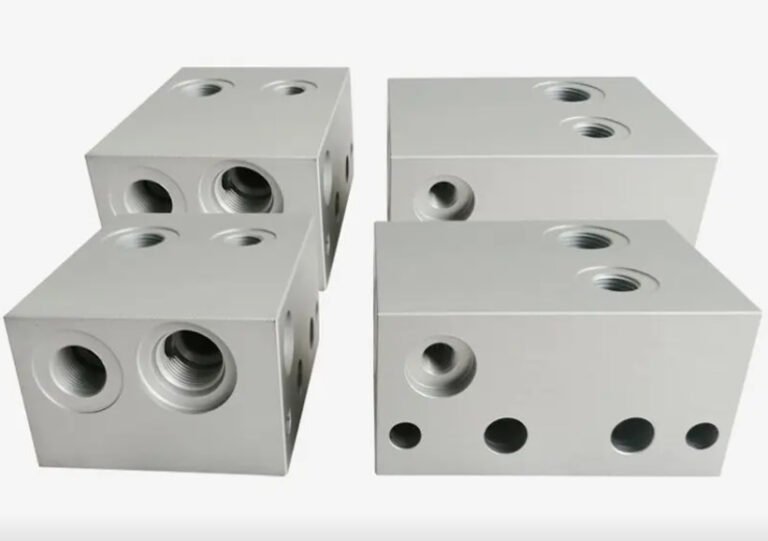
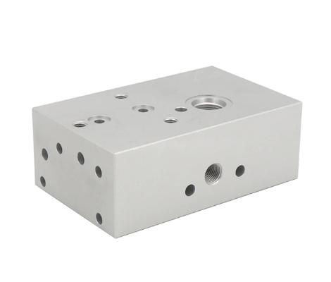
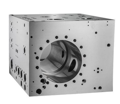
A hydraulic manifold block is the central distribution, control and connection element in many hydraulic systems. It integrates valves, channels and ports in a compact body, providing a reliable and efficient way to route pressurized fluid between pumps, actuators and auxiliary components. This guide explains the functions, internal design logic, material selection and machining processes involved in engineering and producing hydraulic manifold blocks for industrial, mobile and stationary applications.
Fundamental Functions of a Hydraulic Manifold Block
A hydraulic manifold block consolidates multiple hydraulic components and flow paths into a single compact assembly. Its core functions are based on how it manages pressure, flow and directional control in a hydraulic circuit.
Flow Distribution and Consolidation
One of the primary roles of a hydraulic manifold block is to distribute flow from a pump or supply line to multiple actuators or subsystems, and to collect return flow into common lines.
- Combines several valve functions into one block, reducing external hoses and fittings.
- Provides common pressure (P), tank (T) and work (A, B) galleries inside the block.
- Enables balanced distribution of flow to multiple cylinders or motors.
By integrating passages in a rigid block, pressure drops and potential leakage paths can be significantly reduced compared with distributed pipe or hose systems.
Integration of Control Functions
The manifold block acts as a mounting base and internal connection medium for multiple types of hydraulic valves and system elements, such as:
- Directional control valves
- Pressure control valves (relief, reducing, sequence, counterbalance)
- Flow control valves (throttle, flow control and check combinations)
- Check valves and shuttle valves
- Cartridge valves and logic elements
Through drilled or milled channels, the block connects these components into a functional circuit without the need for external piping. This improves the compactness and reduces assembly time of hydraulic power units and control stations.
Pressure Management and Safety
The manifold block is responsible for guiding and limiting working pressure to protect pumps, actuators and pipes. It often houses:
Pressure relief valves: limit maximum system pressure by diverting flow to tank when a setpoint is exceeded.
Pressure reducing valves: maintain lower pressure in specific branches.
Sequence valves: ensure actuators move in a defined order at specified pressures.
The internal passage size, flow cross-sections and pressure ratings of the block must match the maximum working pressure and flow rates defined by the system design.
Leak Reduction and Reliability Improvement
Replacing numerous hoses and fittings with a solid block reduces the number of potential leak points. Sealing is concentrated around valve interfaces and port connections. A correctly designed and machined manifold:
Minimizes internal dead volumes and sharp corners that may trap air or contaminants.
Provides stable support for valves, reducing mechanical stress under pressure cycling.
Improves reliability in harsh operating environments, including heavy mobile machinery, presses and marine applications.
Key Design Elements of Hydraulic Manifold Blocks
Designing a hydraulic manifold block requires systematic consideration of fluid dynamics, mechanical strength, manufacturability and service needs.
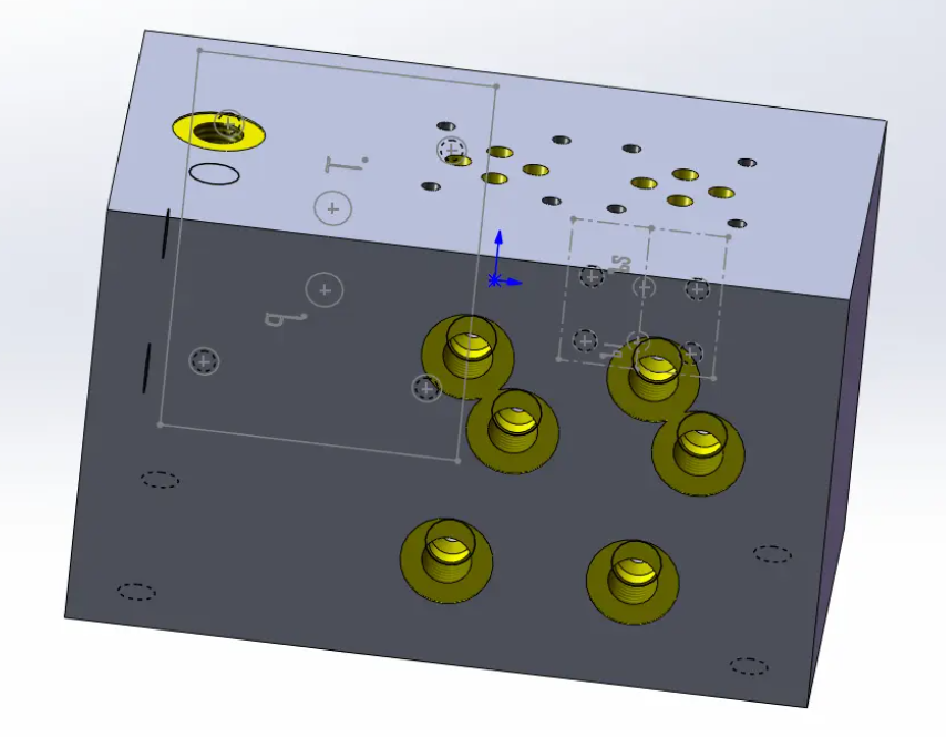
Internal Flow Channel Layout
Internal channels must meet specified flow capacity and pressure drop limits while being compatible with available machining processes. Important aspects include:
Channel diameters: typically selected based on allowable velocity and pressure drop. For mineral oil systems, a common velocity range is approximately 2–4 m/s in pressure lines and 1–2 m/s in suction lines, while return lines may use 2–3 m/s depending on design practice.
Bends and intersections: sharp 90° turns are avoided when possible; larger radii or chamfered intersections are preferred to reduce turbulence and energy losses.
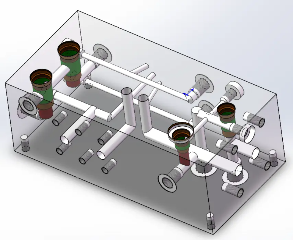
Cross-drilling strategy: channels are created by intersecting drilled holes, often closed with threaded plugs. This provides flexibility but also requires careful planning to avoid weak sections and interference.
Dead zones: stagnant pockets and blind areas are minimized to reduce contamination accumulation and to facilitate flushing.
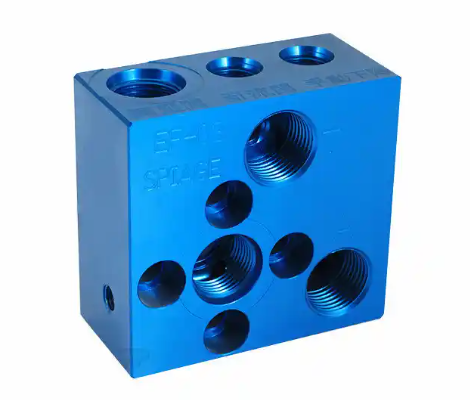
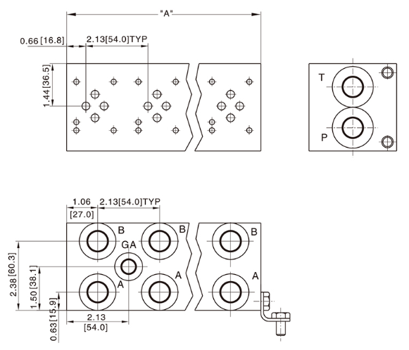
Porting, Valve Interfaces and Standards
Hydraulic manifold blocks generally follow recognized port and valve interface standards to ensure interchangeability and ease of integration. Common standards include:
Threaded ports: BSPP, NPT, metric and UNF threads depending on regional practice.
Flanged connections: ISO 6162 (SAE J518) code 61/62 flanges for higher flows and pressures.
Subplate and manifold patterns: CETOP/NG (ISO 4401) patterns for industrial valves; custom cavities for cartridge valves based on ISO 7789 or manufacturer-specific cavity systems.
When cartridge valves are used, the block must precisely accommodate cavity dimensions, pilot passages and cross-port connections defined in valve datasheets.
Structural Integrity and Stress Considerations
The manifold block must safely withstand static and cyclic pressures without cracking, excessive deformation or fatigue. Design considerations include:
Wall thickness: sufficient material between channels, between channels and outer surfaces, and around threaded ports. Typical minimum wall thickness ranges from 3 mm to 8 mm or more, depending on pressure and material strength.
Distance between intersecting channels: kept larger than the drill diameter to avoid weak spots and drill breakthroughs.
Mounting points: areas for installation on frames or power unit bases should not be excessively weakened by internal drillings.
Finite element analysis (FEA) or analytical stress calculations are often used for blocks operating at higher pressures (for example above 210 bar) or with large cross-sections.
Maintainability and Service Access
Hydraulic systems often require periodic inspection, valve replacement and flushing. Manifold design should therefore consider:
Valve accessibility: adequate space for tools, wrench clearance and possible future valve upgrades.
Test points: integrated test ports for pressure measurement and troubleshooting.
Flushing connections: connections that permit high-flow flushing to remove contamination before commissioning and after maintenance.
Typical Materials for Hydraulic Manifold Blocks
Material selection determines mechanical strength, machinability, corrosion resistance, weight and cost. Different application environments and pressure classes favor different materials.
| Material Type | Typical Use Range | Strength and Pressure Capability | Corrosion and Surface Characteristics |
|---|---|---|---|
| Carbon steel (e.g., C45, 1045) | General industrial and mobile manifolds | High strength, suitable for medium to high pressure (often up to 315 bar and above with proper design) | Requires protective coating or plating to avoid rust |
| Alloy steel | High-pressure, heavy-duty or safety-critical applications | Higher yield and fatigue strength compared to plain carbon steel | Often coated or plated; good for severe pressure cycling |
| Copper / Brass | Low-pressure hydraulic systems, lubrication systems, special corrosion-resistant applications | Lower strength than steel; suitable for low to medium pressure applications | Excellent corrosion resistance; no additional coating required; good resistance to moisture and many fluids |
| Ductile iron (spheroidal graphite iron) | Industrial manifolds and valve bodies | Good mechanical strength and vibration damping | Better corrosion resistance than plain carbon steel; often painted |
| Aluminum alloys (e.g., 6061-T6, 6082-T6) | Mobile equipment, weight-sensitive systems | Suitable for low to medium pressure ranges (commonly up to about 210 bar depending on design) | Good corrosion resistance; often anodized for further protection |
| Stainless steel (e.g., 316L) | Marine, offshore, food, chemical and corrosive environments | Good strength; can be used for high pressure with appropriate design | Excellent corrosion resistance; suitable for aggressive media |
Mechanical Properties and Pressure Rating
The material must provide adequate yield strength, tensile strength and fatigue resistance. Key parameters influencing maximum allowable pressure include:
Yield strength: defines the stress level at which permanent deformation occurs. A safety factor is applied when converting yield strength to allowable pressure.
Fracture toughness: important to resist crack growth arising from stress concentrations or defects.
Fatigue behavior: cyclic pressure loading can initiate fatigue cracks; material fatigue limits and surface conditions are relevant.
Design standards and company guidelines are used to convert these properties into maximum allowable working pressures and safety margins.
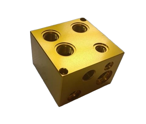
Corrosion Resistance and Surface Protection
Hydraulic fluid itself may protect metal surfaces to some extent, but external surfaces are often exposed to moisture, salt and contaminants. Protection methods include:
Painting and powder coating: commonly used on carbon steel and ductile iron manifolds for industrial environments.
Zinc, nickel or zinc-nickel plating: applied to carbon steel for improved corrosion resistance and aesthetic appearance.
Anodizing (for aluminum): forms a protective oxide layer, which can be thicker for harsh conditions.
Use of stainless steel: chosen where contamination risk, hygiene requirements or aggressive environments justify the higher cost.
Machinability and Cost Considerations
Machining cost constitutes a significant portion of manifold production cost. Material machinability directly influences cycle time, tool wear and surface finish quality.
Aluminum alloys: relatively easy to machine, allowing shorter cycle times and good surface quality with standard tooling.
Carbon and alloy steels: require more robust tooling and careful cutting parameter selection; heat treatment state (normalized, quenched and tempered) affects machinability.
Stainless steel: more difficult to machine due to work hardening; demands rigid setups and optimized cutting conditions.
The optimum choice often balances mechanical performance, corrosion protection requirements, available equipment and target production costs.
Machining Processes for Hydraulic Manifold Blocks
Hydraulic manifold block manufacturing requires a combination of machining processes to achieve internal channels, mounting surfaces, threads and precise valve cavities. Process planning is strongly influenced by block size, complexity and production volume.
Raw Material Preparation and Pre-Machining
Production typically begins with bar stock, plate or near-net forging/casting. Preparation steps can include:
Saw cutting or flame cutting to approximate block dimensions with allowance for machining.
Stress relieving heat treatment for steel or ductile iron blocks to minimize distortion during machining.
Rough milling of outer surfaces to establish datum faces and reference edges.
Drilling and Deep-Hole Machining
The majority of internal flow channels in a manifold are created by drilling operations.
Standard drilling: used for short and medium-length channels with typical diameters corresponding to flow requirements.
Gun drilling or deep-hole drilling: applied for long channels with larger length-to-diameter ratios. Centering, guidance and chip evacuation are critical.
Reaming: used after drilling to improve dimensional accuracy and surface finish where required.
Intersection drilling requires precise coordination of drilling paths to ensure proper connection without undesired breakthrough or weakening of walls.
Threading, Tapping and Port Finishing
Ports for pipes, hoses, test fittings and plugs are produced through:
Tapping: for internal threads such as BSPP, NPT, metric or UNF. Accuracy of pitch diameter and perpendicularity to sealing faces is important.
Thread milling: used when higher thread quality and flexibility are required, particularly in CNC machining centers.
Countersinking and spot facing: create smooth, flat seals for O-ring face seals, banjo fittings or flange connections.
Threaded plug holes for closing cross-drilled channels are machined with attention to thread engagement length and sealing method (for example O-ring, metal seal or sealant).
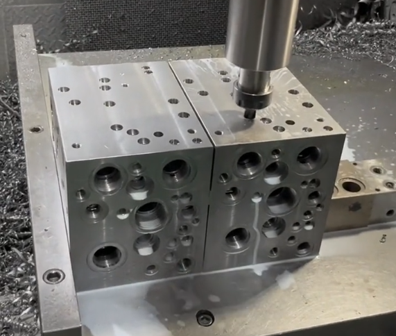
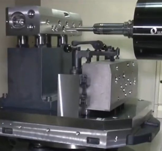
CNC Milling and Complex Geometry
CNC milling is used to produce external shapes, mounting features, pockets and complex surfaces. It is also applied to some internal geometries that cannot be created by drilling alone.
Flat mounting surfaces: provide accurate and rigid support for valves and subplates.
Recesses and pockets: house cartridge valves, relief valves or integrated sensor elements.
Precision grooves: hold O-rings or special seals around ports and valve cavities.
Multi-axis CNC machines can reduce setups by machining multiple sides of the block in a single clamping, enhancing accuracy and reducing cycle time.
Precision Machining of Valve Cavities
Cartridge valve manifolds require accurately machined cavities with tight tolerances. Typical features include:
Stepped diameters: multiple cylindrical sections with specific diameters and depths according to valve manufacturer specifications.
Sealing surfaces: defined by specified surface roughness (for example Ra 0.8–1.6 µm) to ensure reliable O-ring or metal-to-metal sealing.
Coaxiality and concentricity: critical for proper valve operation and to avoid leakage or uneven loading.
Finishing methods can include boring, reaming and honing, depending on required tolerance classes.
Deburring, Cleaning and Surface Finishing
Deburring and cleaning are vital steps for hydraulic manifolds, as burrs or contamination can damage valves and actuators.
Mechanical deburring: removal of burrs from drilled holes and intersecting channels using brushes, abrasive tools or specialized deburring equipment.
Thermal deburring: controlled combustion process used for complex internal passages where mechanical access is limited.
Ultrasonic or high-pressure washing: removes chips, cutting fluids and fine particles from internal channels.
After cleaning and inspection, external surfaces may be plated, anodized or painted according to the chosen corrosion protection method.
Dimensional Tolerances, Surface Finish and Sealing
Functional performance and leak-free operation depend on adherence to specified tolerances and surface finish standards.
Dimensional Tolerances and Geometric Accuracy
Typical tolerance requirements include:
Port and cavity diameters: tolerance classes selected based on valve manufacturer recommendations, often in the range of IT7–IT9 or better.
Flatness of mounting surfaces: must ensure proper sealing, typically within a few hundredths of a millimeter for smaller blocks.
Perpendicularity and parallelism: required between valve mounting faces, port axes and reference surfaces.
Geometric dimensioning and tolerancing (GD&T) is frequently used to specify positional tolerances for ports and cavities to ensure compatibility with standardized or custom valve patterns.
Surface Roughness and Contact Sealing
Surface roughness affects sealing performance, friction and wear.
O-ring sealing lands: usually require Ra around 0.8–1.6 µm for reliable sealing without excessive wear.
Metal-to-metal sealing faces: can require finer roughness depending on seal design; lapping or fine grinding may be used.
General external surfaces: often have a roughness appropriate for painting or coating without impacting functionality.
Sealing Methods and Interface Types
Various sealing solutions are used at manifold interfaces:
O-ring seals: widely adopted for valve cavities, subplate interfaces and some threaded plug applications.
Soft metal or composite seals: employed in high-temperature or special chemical environments.
Gasket seals: rarely used for high-pressure interfaces but may appear on low-pressure covers.
Thread sealing: PTFE tape, anaerobic sealants or special sealing threads may be applied where secondary sealing is required.
Design and Production Issues and Considerations
Hydraulic manifold blocks must meet demanding operational requirements while remaining practical to manufacture and maintain. Several common issues need careful attention during design and production.
Internal Leakage and Cross-Port Contamination
Inadequate sealing or dimensioning errors can cause unintended flow paths between channels or ports.
If port locations or passages deviate from design, valves may not fully isolate circuits, leading to actuator drift, loss of holding capability or instability.
Maintaining precise alignment of valve cavities and sealing surfaces is essential to avoid internal leakage.
Stress Concentrations and Crack Formation
Improperly located cross drillings, thin walls or sharp transitions can cause stress concentrations. Under cyclic pressure, these may lead to crack initiation and propagation.
Common critical regions include:
Intersections of large-diameter channels close to mounting holes.
Areas near high-pressure ports with insufficient surrounding material.
Regions subjected to external loads such as clamping or mounting bolts.
Design rules often define minimum distances between channels, minimum edge distances and smooth transitions to mitigate these risks.
Chips and Contamination Retention
Hydraulic manifolds have multiple intersecting passages that can trap chips and contaminants if cleaning is inadequate.
Residual chips can migrate during operation and damage valve seats, spools and seals.
To reduce contamination risk, design and process planning may include:
Orientation of channels to facilitate flushing.
Adequate flushing ports for cleaning after machining.
Verification procedures for cleanliness, such as gravimetric or particle counting methods.
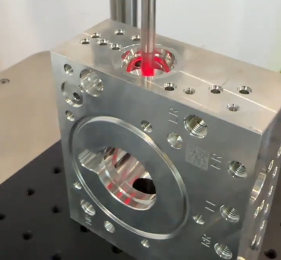
Assembly Errors and Misconnection
Complex manifolds with numerous similar ports and cavities can be prone to assembly errors.
Incorrect valve placement, wrong orientation or misconnection of external lines can cause unsafe operation or reduced performance.
Clear marking of ports, engraving of circuit identifiers and standardized orientation of valve patterns help reduce assembly mistakes.
Inspection, Testing and Quality Assurance
Effective inspection and testing ensure that hydraulic manifold blocks perform as intended and meet safety requirements.
Dimensional and Visual Inspection
Dimensional inspection includes measurement of external dimensions, port locations, cavity diameters, depths and surface flatness. Tools and methods include:
Coordinate measuring machines (CMM) for complex geometries and positional tolerances.
Plug gauges and thread gauges for verifying ports and threaded holes.
Surface roughness testers for critical sealing surfaces.
Visual inspection checks for surface defects, incomplete deburring and coating quality.
Pressure and Leakage Testing
Pressure testing confirms structural integrity and sealing performance.
Hydrostatic testing: manifold is filled with fluid and pressurized to specified test pressure (often above maximum working pressure) to check for cracks or deformation.
Leak testing: may involve air or hydraulic fluid at defined pressure; external leakage is observed at ports, plugs and around valve interfaces.
In some cases, functional testing of the complete manifold assembly with valves and actuators is conducted to validate circuit performance.
Documentation and Traceability
For safety-critical or regulated industries, documentation and traceability are important.
Key aspects include:
Material certificates documenting chemical composition and mechanical properties.
Inspection records with measurement results and test parameters.
Unique identification of each block for future reference, maintenance and failure analysis.
| Inspection / Test Item | Purpose | Typical Methods |
|---|---|---|
| Dimensional accuracy | Verify conformity to design and ensure valve and port compatibility | CMM, calipers, micrometers, gauges |
| Surface flatness and roughness | Ensure sealing reliability and proper mounting | Flatness measurement, roughness tester |
| Internal cleanliness | Prevent damage to valves and actuators from contamination | Visual checks, flushing, particle counting |
| Pressure and leakage performance | Confirm structural integrity and sealing | Hydrostatic test, leak test |
| Coating and corrosion protection | Ensure durability in specified environment | Visual inspection, thickness measurement |
Application Examples and Configuration Types
Hydraulic manifold blocks are used across diverse industries and system scales. Their configuration is determined by required functions, flow rates and installation constraints.
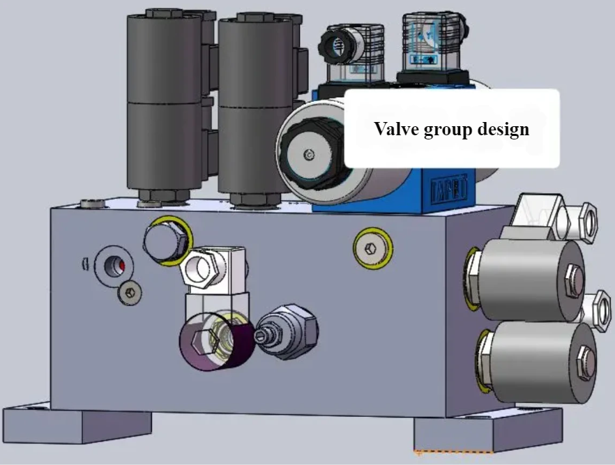
Industrial Hydraulic Power Units
In industrial power units for presses, machine tools, injection molding machines or test rigs, manifold blocks provide centralized control and distribution.
Typical features include:
Integration of multiple CETOP/ISO valve stacks.
Main pressure regulation and safety relief circuits.
Separate manifolds for pump groups, actuator groups or auxiliary functions.
Mobile Machinery and Compact Manifolds
In mobile equipment such as excavators, loaders, agricultural machinery and municipal vehicles, compact and lightweight manifolds are critical.
Common characteristics are:
Use of aluminum manifolds for weight reduction where operating pressures allow.
Integration of cartridge valves to obtain high function density.
Custom shapes to fit restricted installation spaces.
Special-Purpose and Custom Manifolds
Custom manifold blocks are engineered to support specialized functions such as:
Multi-axis motion control in handling and robotics systems.
Safety circuits for lifting, lowering and load holding.
Hydrostatic drive control with integrated logic for motors and braking systems.
These manifolds often combine multiple circuit functions into a single block, requiring careful design coordination between hydraulic engineers and manufacturing engineers.
Select Hydraulic Manifold Block Materials and Precision Machining
XCM offers expertly selected hydraulic manifold block materials combined with advanced precision machining to ensure superior performance, reliability, and durability. From high-strength steel and ductile iron to lightweight aluminum alloys, each material is chosen to meet demanding pressure, flow, and environmental requirements. With CNC machining, strict quality control, and tight tolerances, our hydraulic manifold blocks deliver excellent sealing, optimized flow paths, and long service life—making them ideal for high-performance hydraulic systems across industrial, mobile, and engineering applications.
FAQ About Hydraulic Manifold Blocks
What is a hydraulic manifold block?
A hydraulic manifold block is a solid metal block that contains drilled passages to route hydraulic fluid between valves, pumps, actuators, and other components in a hydraulic system.
What are the main benefits of using hydraulic manifold blocks?
Hydraulic manifold blocks reduce the need for external piping and hoses, minimize leakage points, save space, improve system reliability, and simplify installation and maintenance.
What materials are commonly used for hydraulic manifold blocks?
Common materials include aluminum, carbon steel, stainless steel, and ductile iron. The choice depends on pressure requirements, operating environment, and corrosion resistance needs.
How do I choose the right hydraulic manifold block for my system?
Key factors include operating pressure, flow rate, number of valves, system layout, environmental conditions, and compatibility with existing hydraulic components.
How is quality ensured for hydraulic manifold blocks?
Quality is ensured through precision CNC machining, pressure testing, leak testing, dimensional inspection, and strict quality control procedures.
