
Coordinate Measuring Machines (CMMs) are core instruments in dimensional metrology, enabling accurate 3D measurement of parts and assemblies. They translate the physical geometry of components into precise digital coordinates used for verification, analysis, and quality control.
Fundamental Principles of CMM Measurement
A Coordinate Measuring Machine determines the geometry of an object by acquiring a set of discrete points on its surface, then mathematically reconstructing features such as planes, cylinders, cones, spheres, and freeform surfaces.
Coordinate Systems and Reference Frames
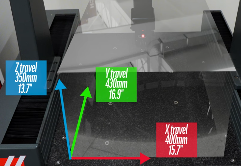
CMM measurement is based on Cartesian coordinate systems:
- Machine coordinate system: Fixed to the CMM structure, typically X (left–right), Y (front–back), and Z (up–down).
- Workpiece coordinate system: Defined relative to the part using datums (e.g., primary plane, secondary plane, tertiary axis).
- Feature coordinate system: Specific to features such as holes or slots, useful for local analysis and pattern measurements.
The transition between coordinate systems is achieved through transformations (translation and rotation) computed during part alignment. This allows the measured data to be interpreted in part design coordinates, usually defined by GD&T and CAD models.
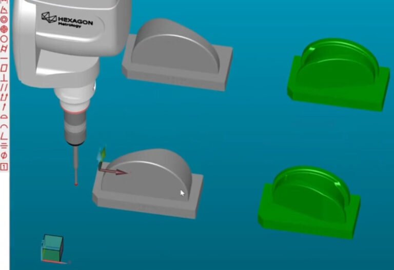
Point Acquisition and Geometric Reconstruction
The probe contacts or scans the part and records point coordinates (X, Y, Z). From these:
- Discrete point sets are fitted to ideal geometric elements using least-squares or other fitting algorithms.
- Derived parameters such as diameter, flatness, circularity, position, and profile are computed from fitted features.
- Measurement results are compared against nominal data from drawings or CAD models, with deviations and tolerances evaluated.
Higher point density generally improves feature definition, particularly for complex surfaces, but increases measurement time and data volume.
Probing Principles
Probing converts physical contact or optical interaction into precise coordinate data. Two basic modes are widely used:
Touch-trigger probing uses a stylus with a ruby or similar ball tip. Contact with the part deflects the stylus and generates an electrical signal to “trigger” point capture. This is common for discrete-point measurements.
Scanning probing maintains contact and continuously samples points while moving along a feature. This provides high-density data, suitable for form, profile, and freeform surface evaluation.
Main Types of Coordinate Measuring Machines
CMMs are categorized mainly by structural configuration and motion system. Each type serves specific part sizes, accuracy ranges, and production environments.
Bridge CMM
Bridge CMMs are the most common configuration. A rigid bridge spans the granite or ceramic table, with the probe head moving in three axes:
- X-axis: Typically the table movement or bridge crossbeam movement.
- Y-axis: Movement of the bridge along the table.
- Z-axis: Vertical movement of the ram carrying the probe.
Bridge CMMs offer a good balance of accuracy, stability, and cost, suitable for small to medium-sized components in industries such as automotive, aerospace, and precision machining.
Gantry CMM
Gantry CMMs scale up the bridge concept for large and heavy workpieces. The structure spans over the part, which can remain stationary on the floor or a large base:
- Suitable for large aerospace structures, vehicle bodies, and heavy casting inspection.
- Often installed in dedicated measuring halls with controlled environmental conditions.
Gantry designs allow measurement of large envelopes while maintaining relatively high accuracy through robust machine structures and advanced compensation.
Cantilever CMM
Cantilever CMMs have a single-sided support for the horizontal arm, allowing easier access for loading and unloading:
- Preferred for measuring smaller, relatively light parts requiring frequent manual access.
- Commonly used near production lines and for applications where the operator frequently interacts with the part during measurement.
The open structure improves accessibility but usually limits the measuring volume and can impact stiffness compared with bridge configurations.
Horizontal Arm CMM
Horizontal arm CMMs use one or two horizontal arms that move along a base. They are often used for:
- Automotive body-in-white inspection, panels, and large sheet metal assemblies.
- Direct access to vertical surfaces and interior regions of large structures.
These CMMs are usually installed in measurement cells integrated with production, focusing on accessibility and measurement of large, complex assemblies.
Portable and Articulated CMMs
Portable CMMs provide flexibility in measuring directly on the shop floor or on very large parts. The most common types include:
- Articulated arm CMMs: A multi-joint arm with encoders at each joint, allowing manual positioning of the probe in 3D space.
- Laser trackers: Use laser interferometry or absolute distance measurement to track a reflector target, determining its position in space.
These systems allow in-situ measurement of large components, alignment tasks, and fixture verification, often where moving parts to a fixed CMM is impractical.
Core Components and Hardware Architecture
A typical CMM consists of the machine structure, drive system, probing system, controller, and environmental supports. Proper integration and calibration of these components determine performance.
Machine Structure and Guideways
The structural frame, usually made of granite, ceramic, or cast aluminum, provides stiffness and thermal stability. Precision guideways and air bearings minimize mechanical friction and hysteresis:
- Air bearings: Supply a thin film of air between moving and fixed surfaces to achieve nearly frictionless movement.
- Linear guideways: Precisely machined surfaces or rails guiding the motion in X, Y, and Z.
- Granite base: Often used due to good thermal stability and vibration damping.
The overall geometry of the machine structure is calibrated and compensated so that the axes remain orthogonal and the scale factors remain accurate over the measuring volume.
Drive and Encoder Systems
CMM axes are driven by motorized systems such as DC or AC servomotors, often connected through precision gear or belt mechanisms. Feedback is provided by:
- Linear encoders: Measure the position along each axis, typically with resolutions down to sub-micron levels.
- Rotary encoders: Used in rotary tables, articulated arms, or probe heads to track angular positions.
Closed-loop control coordinates axis motion and ensures smooth, precise path following. The controller compensates for dynamic effects and ensures that the probe contacts the part at controlled speeds.
Probes, Probe Heads, and Styli
Probing hardware is a crucial contributor to CMM performance. Several types are used depending on the measurement task and required accuracy.
| Probe Type | Operating Principle | Typical Application |
|---|---|---|
| Touch-trigger probe | Mechanical contact triggers a signal at deflection threshold | Discrete point measurements of prismatic features, general inspection |
| Analog scanning probe | Continuous contact, analog deflection measurement | Form and profile evaluation, freeform surfaces |
| Optical or video probe | Non-contact imaging and edge detection | Small, delicate, or soft parts; micro-features |
| Laser scanning probe | Laser line or point, triangulation or time-of-flight | High-density surface capture for reverse engineering |
| Articulating probe head | Indexing or continuous rotation of probe orientation | Access to complex geometries without repositioning the part |
Styli selection (ball diameter, length, material, and stem stiffness) directly influences uncertainty and accessibility. Longer and thinner styli increase reach but introduce greater deflection and potential error.
Controllers and Measurement Software
The CMM controller synchronizes axis motion, probe triggering, and data acquisition. Measurement software provides:
- CAD model import and nominal feature definition.
- Measurement strategy planning and path generation.
- GD&T evaluation and reporting.
Software also handles alignment, fitting algorithms, uncertainty contributions, and export of data to quality systems or manufacturing execution systems.
Measurement Parameters and Performance Specifications
CMMs are specified and verified using standardized performance metrics to ensure they meet accuracy requirements for their intended use.
Key Accuracy and Uncertainty Parameters
The performance of a CMM is commonly characterized by:
- Length measurement error (E): Maximum allowable error when measuring calibrated gauge blocks or step gauges across the volume.
- Probing error (P): Error associated with single-point probing of spheres or artifact features.
- Form measurement error: Errors in measuring roundness, flatness, or straightness from calibrated artifacts.
- Repeatability: Variation in repeated measurements of the same feature under identical conditions.
Accuracy is often expressed in the form E = A + L/K, where A is a constant term in micrometers, L is the measured length in millimeters, and K is a factor specifying how error scales with length.
Standards and Verification Methods
CMM performance verification is performed according to standards such as ISO 10360 series or equivalent regional standards. Typical procedures include:
- Length tests across the working volume using calibrated artifacts.
- Probing tests using calibrated test spheres for probing repeatability and form.
- Diagonal and volumetric tests to evaluate machine geometry and compensation.
Routine verification ensures that the CMM continues to operate within specified limits under actual environmental conditions.
CMM Probing Modes and Measurement Strategies
Effective CMM use depends not only on machine performance but also on the probing strategies and measurement planning applied to parts.
Discrete Point Measurement
Discrete point, or point-to-point, measurement collects a limited number of points on each feature. It is used for:
- Simple features such as planes, cylinders, and cones.
- Verification of hole positions, diameters, and basic dimensions.
- Applications where measurement time is critical and lower data density is acceptable.
Careful selection of point distribution is necessary to represent the feature adequately, especially where form deviations may exist.
Scanning and High-Density Measurement
Scanning measurement collects thousands of points along a single path or across a surface. It is particularly valuable for:
- Evaluating form tolerances such as circularity, cylindricity, and profile of a line or surface.
- Confirming freeform surfaces against CAD models.
- Reducing uncertainty due to local form defects by averaging behavior over larger areas.
Scanning paths, speeds, and probe forces must be selected considering part material, geometry, and required accuracy.
On-Machine Alignment and Datum Strategies
Accurate measurement requires reliable establishment of part datums. Common practices include:
- Using three non-collinear points to define a primary datum plane.
- Using two points or a line to define a secondary datum direction.
- Using a single point, axis, or feature to establish the tertiary datum.
Alignments can be based on physical datums, functional surfaces, or best-fit alignment to minimize differences between measured and nominal CAD data.
Measurement Workflow on a CMM
A systematic measurement workflow enhances repeatability, comparability, and traceability of results, especially in production environments.
Part Preparation and Fixturing
Before measurement, the following steps are typical:
- Cleaning the part to remove oil, dust, and burrs that can affect contact.
- Stabilizing the part to the measurement room temperature, often around 20°C, for sufficient time.
- Fixturing the part securely, avoiding deformation and allowing access to features without obstruction.
Fixtures should be dimensionally stable, non-deforming, and compatible with the measuring task, sometimes using modular fixture systems for flexibility.
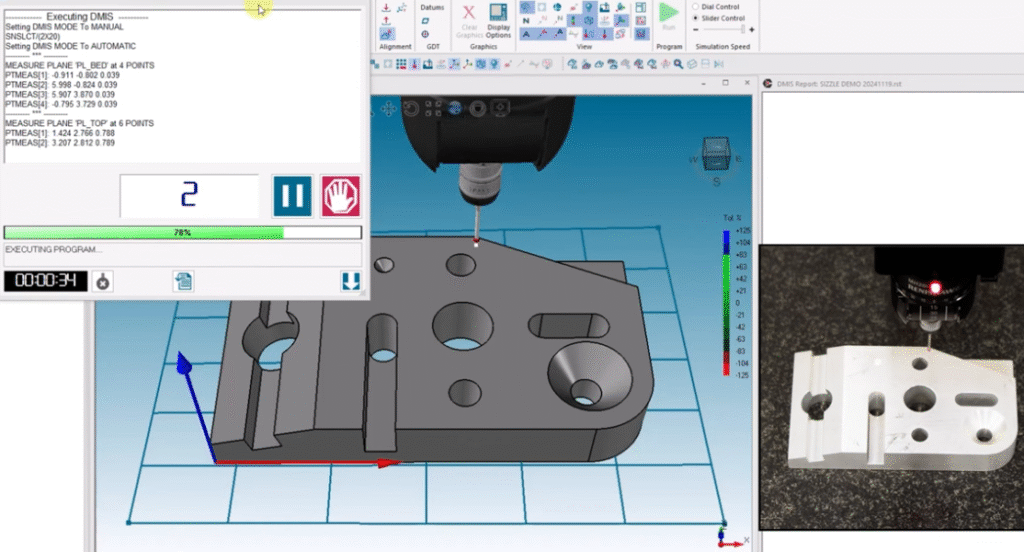
Program Setup and Execution
Measurement plans may be created offline from CAD or interactively at the CMM. Typical operations include:
- Defining the part coordinate system using datum features.
- Selecting features to be measured and specifying measurement paths.
- Assigning GD&T requirements and tolerances for evaluation.
Programs can be executed in automatic mode for repeated inspection of similar parts or in manual mode for one-off measurements and setup tasks.
Data Analysis and Reporting
Measurement software processes the acquired data to:
- Fit geometric features and determine deviations from nominal.
- Evaluate dimensions, limits, and GD&T characteristics such as position, profile, orientation, and form.
- Generate graphical and statistical reports summarizing results.
Reports can include color maps comparing measured surfaces with CAD models, tabular dimension lists, and SPC indicators for process control purposes.
Calibration, Compensation, and Environmental Control
CMM performance depends heavily on calibration procedures, thermal management, and environmental stability. These factors directly influence measurement reliability.
Machine Calibration and Error Mapping
Calibration establishes the relationship between encoder readings and true space coordinates. It typically involves:
- Axis calibration: Determining scale, straightness, and angular deviations along each axis.
- Volumetric error mapping: Creating compensation tables that account for geometric errors across the measurement volume.
- Probing system calibration: Establishing stylus ball radius, stylus length, and orientation by probing calibration spheres or artifacts.
Calibration data are stored in the controller or software and applied automatically to correct raw measurements during operation.
Thermal Effects and Compensation
Dimensional measurement is highly sensitive to temperature. Thermal effects include:
- Expansion or contraction of the machine structure and scales.
- Expansion of the workpiece based on its coefficient of thermal expansion.
- Non-uniform temperature gradients causing localized distortions.
Temperature sensors attached to the machine and sometimes to the part provide inputs for active compensation. Measurements can be normalized to a reference temperature, commonly 20°C, using known expansion coefficients.
Environmental Conditions and Vibration Control
To maintain specified performance, CMMs are usually installed in controlled environments with:
- Stable temperature and humidity within specified limits.
- Low air currents and minimal dust to protect air bearings and optical components.
- Vibration isolation through dedicated foundations, isolators, or structural design.
Control of environmental influences reduces measurement uncertainty and ensures consistent performance over time.
Industrial Applications of CMM Measurement
CMMs are applied across many industries wherever precise dimensional verification is required. Their flexibility and accuracy make them suitable for both development and production phases.
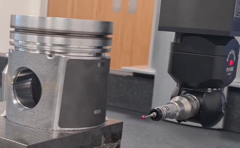
Automotive Industry
In automotive manufacturing, CMMs are used to measure:
- Engine components such as cylinder blocks, heads, crankshafts, and pistons.
- Transmission and drivetrain parts where tight tolerances are critical.
- Body-in-white structures and panels for assembly accuracy and gap/flush control.
Bridge and horizontal arm CMMs, as well as portable systems, are frequently used to integrate measurement with production lines for rapid feedback on dimensional quality.
Aerospace and Defense
Aerospace components often require complex geometry and strict tolerances. CMMs help verify:
- Rotating components such as turbine blades, disks, and blisks.
- Structural parts, wing components, and fuselage sections.
- Precision machined parts for hydraulic, fuel, and control systems.
Gantry CMMs and specialized fixtures are common for large-grade aerospace structures, complemented by scanning probes for freeform surfaces.
Precision Engineering and Tooling
CMMs are widely used in tool and die, mold manufacturing, and precision machining for:
- Verification of mold cavities and cores, die surfaces, and punch geometry.
- Measurement of precision gauges and reference artifacts used in production.
- Alignment and verification of complex fixtures and jigs.
High-accuracy bridge CMMs with scanning capabilities and high-resolution probing are often chosen for these applications.
Medical and Consumer Products
In medical device and consumer product manufacturing, CMMs support measurement of:
- Implants, orthopedic components, and surgical tools.
- Plastic and polymer components requiring geometric accuracy.
- Assemblies where fit, function, and ergonomics depend on precise dimensions.
Non-contact and optical probing is used where parts are delicate, small, or sensitive to contact forces.
Considerations and Practical Issues in CMM Use
While CMMs provide high capability, their effective use requires attention to practical issues, measurement planning, and resource constraints.
Measurement Uncertainty and Influencing Factors
Total measurement uncertainty is influenced by:
- Machine errors, including geometry, probing, and thermal effects.
- Part-related factors such as surface roughness, material properties, and temperature.
- Measurement strategy including probing patterns, speeds, and styli selection.
- Operator skills and consistency in part setup and program execution.
Uncertainty analyses and validation measurements help quantify the reliability of results and support decision-making in quality control.
Typical Pain Points in Production Environments
Some recurring issues when using CMMs in manufacturing include:
- Throughput limitations when many parts require full inspection with detailed CMM programs.
- Machine availability constraints when a single CMM serves multiple lines or processes.
- Training requirements for operators and programmers to correctly interpret GD&T and design efficient measurement plans.
- Sensitivity to environmental conditions in areas not fully conditioned or isolated from production influences.
Balancing measurement depth with production demands often requires optimization of inspection strategies and selective feature measurement.
Comparison with Other Dimensional Measurement Methods
CMMs are part of a broader set of dimensional measurement techniques. Understanding their characteristics relative to other methods supports appropriate technology selection.
| Method | Typical Use | Strengths | Considerations |
|---|---|---|---|
| CMM (bridge/gantry) | High-accuracy 3D measurement of small to large parts | Flexible, high accuracy, GD&T capable, CAD integration | Requires controlled environment, programming, and setup time |
| Articulated arm CMM | On-site measurement of large or fixed assemblies | Portable, flexible, suitable for large parts | Typically lower accuracy than fixed CMMs, operator-dependent |
| Optical vision system | Small components, 2D features, and micro-details | Non-contact, high resolution in 2D, fast for certain tasks | Limited for deep 3D features and heavy parts |
| Hand tools (calipers, micrometers) | Simple dimensions and quick checks | Low cost, easy to use, immediate results | Limited accuracy and complexity, operator influence |
| Dedicated gauges and fixtures | High-volume production checks | Fast, simple for operators, suitable for repetitive checks | Low flexibility, cost for design and fabrication, limited detail |
Selection of CMMs or alternative methods depends on tolerances, part complexity, batch sizes, and integration with process control systems.
