
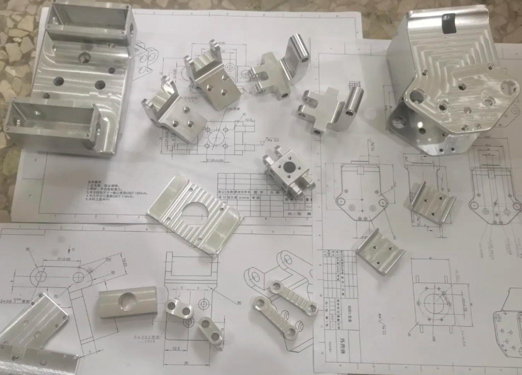
High-volume CNC machining often starts from a proven prototype process, then scales to thousands or millions of parts. Many teams discover that what worked for ten parts per week becomes unstable when machines run continuously, tools wear faster, and small variations accumulate. This guide explains how to design, validate, and run high-volume CNC production so that throughput and quality remain under control.
What High-Volume CNC Machining Actually Involves
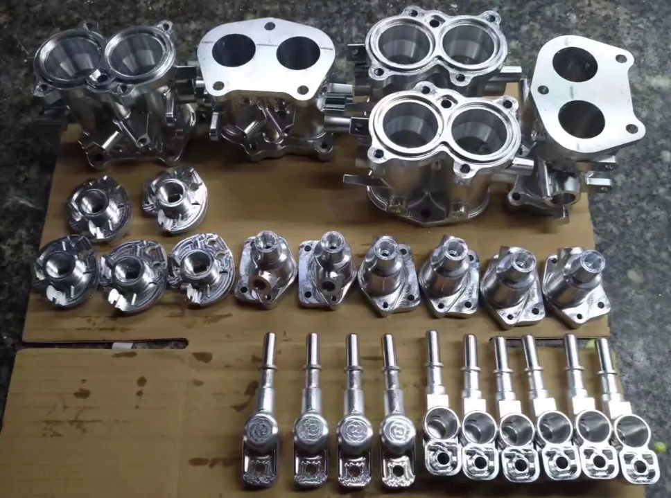
High-volume CNC machining is not just “more of the same” prototype work. It combines repeatable machining processes, stable equipment, standardized tooling, and robust inspection into a system that can sustain long production campaigns with predictable output.
Key characteristics include:
- Large batch sizes or continuous production
- Tight control of cycle time and equipment uptime
- Consistent dimensional and surface quality over long runs
- Formal documentation for processes, tooling, and inspection
The core objective is to maintain process capability and repeatability at scale, not just to produce a few good sample parts.
Production Requirements Versus Prototype Machining
Prototype machining focuses on flexibility and speed of change. High-volume machining focuses on stability, repeatability, and total cost per part.
| Aspect | Prototype Machining | High-Volume CNC Machining |
|---|---|---|
| Primary objective | Design validation and feasibility | Stable, repeatable output at target volume |
| Process changes | Frequent, informal, on-the-fly | Controlled, documented, validated before release |
| Tooling | General-purpose, small batches | Standardized, preset, with defined tool life rules |
| Fixtures | Simple, manually adjusted | Rigid, modular, optimized for quick loading |
| Inspection | Intensive per part, flexible criteria | Sampling plans, gauges, SPC, reaction plans |
| Documentation | Minimal, focused on CAM and setup notes | Formal process sheets, control plans, work instructions |
| Cost focus | Per-project, low NRE cost | Per-part cost, including tooling and downtime |
Using a prototype process unchanged for volume production often exposes limitations in fixturing, cycle time, and dimensional stability that were not apparent at low quantities.
Core Elements of a Stable High-Volume CNC Process
Stable production comes from aligning equipment capability, tooling strategy, fixturing, and inspection. Each element must be defined and controlled.
Machine Tool Capability and Configuration
Machine selection and configuration define the achievable envelope of precision, cycle time, and availability.
Typical technical considerations include:
- Spindle power and torque versus material removal rate
- Thermal stability and warm-up behavior
- Axis acceleration, deceleration, and positioning accuracy
- Tool magazine capacity and tool change time
- Coolant flow rate and pressure
For example, machining hardened steel with large axial depths and high feed rates may require a spindle power rating above 25 kW and sufficient torque at low to medium rpm. For aluminum with aggressive high-speed machining, priority may be high rpm (18,000–30,000 rpm range) and enough axis acceleration to leverage high feed rates.
Tooling Strategy
Tool selection and management are central to high-volume machining. Important parameters:
Tool type and grade must match material, expected cutting speed, and required surface quality. Carbide tools are common for steel and aluminum, while cermet or PCD tools may be used for finishing non-ferrous materials and composites.
Tool life must be defined as a measurable limit:
- Parts per edge
- Cutting length (m or ft) per edge
- Cutting time (minutes) per edge
Example: A finishing end mill may be limited to 60 minutes of cutting time or 800 machined parts, whichever occurs first, to keep surface finish and dimensional drift within specification.
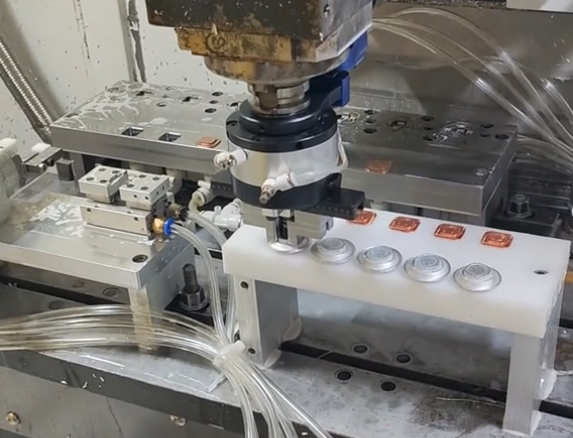
Fixturing and Workholding
Fixturing must provide repeatable location and sufficient clamping force without deforming the part. Important elements include:
Locating schemes such as three-point locating for planar surfaces, pins for holes, and dedicated datum features. Clamping methods can include mechanical clamps, hydraulic fixtures, or pneumatic clamping for shorter cycle times.
Measured fixture repeatability (for example, ±0.005 mm) should be well within the total tolerance budget, leaving room for tool wear and machine variation.
Cutting Parameters and Stability Window
Cutting parameters (spindle speed, feed per tooth, radial and axial depth of cut) define the process window. High-volume processes use validated recipes rather than ad hoc parameter choices.
For each tool and operation, the process window can be expressed as ranges such as:
Spindle speed: 8,000–10,000 rpm; Feed per tooth: 0.05–0.08 mm/tooth; Axial depth: 1.5–2.0×D; Radial depth: 0.3–0.5×D.
Process capability analysis (Cp, Cpk) is then performed under these settings. If Cpk is consistently above the required minimum (often 1.33 or 1.67), the parameters are released for production.
Dimensional Control and Process Capability
High-volume machining requires statistical evidence that the process can hold tolerances over long runs.
Tolerance Allocation and Stack-Up
Each dimension’s tolerance must be decomposed into contributions from machine accuracy, thermal drift, fixture repeatability, tool deflection, and tool wear. A simplified tolerance stack might assign:
- 30–40% of the tolerance to machine and fixture variation
- 20–30% to tool wear and deflection
- 10–20% to measurement uncertainty
- The remaining margin as process safety
For a 0.02 mm total tolerance, a common target is to keep process variation (6σ) within 0.013–0.015 mm, leaving a small reserve margin.
Process Capability Indices
Capability indices quantify how well the machining process fits within specified limits.
Cp measures the ratio between tolerance width and process spread (6σ). Cpk accounts for process centering relative to the nominal dimension. In high-volume CNC machining, common requirements are:
- Cp ≥ 1.33 for standard production
- Cpk ≥ 1.33, often 1.67 for critical safety or functional features
Capability studies typically use at least 50–125 consecutive parts. Critical dimensions are measured and charted, and actions are defined if capability indices fall below the target values.
Measurement Systems and Gauging
Measurement systems must be stable and repeatable. Typical components are:
- In-machine probing for reference features and offset updates
- Offline gauging with calipers, micrometers, height gauges, and bore gauges
- CMMs for complex profiles and geometric tolerances
Gauge capability is validated using Gauge R&R studies. A typical requirement is total Gauge R&R less than 10% of the total tolerance, with 10–20% sometimes acceptable depending on application and risk level.
Cycle Time, Throughput, and OEE
High-volume machining performance depends on controlled cycle time, high utilization, and minimal unplanned downtime.
Breaking Down CNC Cycle Time
Cycle time per part can be decomposed into:
- Cutting time: time spent removing material
- Non-cut time: tool changes, rapid moves, probing, coolant on/off
- Loading/unloading time: manual or automated
For example, a 90-second total cycle might include 60 seconds cutting, 15 seconds tool changes and rapid moves, and 15 seconds part handling. Optimization aims to increase cutting time share and minimize non-cut components without compromising stability.
Overall Equipment Effectiveness (OEE)
OEE is a commonly used composite metric:
OEE = Availability × Performance × Quality.
Typical targets in mature production environments are:
- Availability above 85–90%
- Performance (actual vs. theoretical cycle) above 90–95%
- Quality yield above 99–99.5%
Even with strong cycle time performance, low availability or high scrap can significantly reduce effective output.
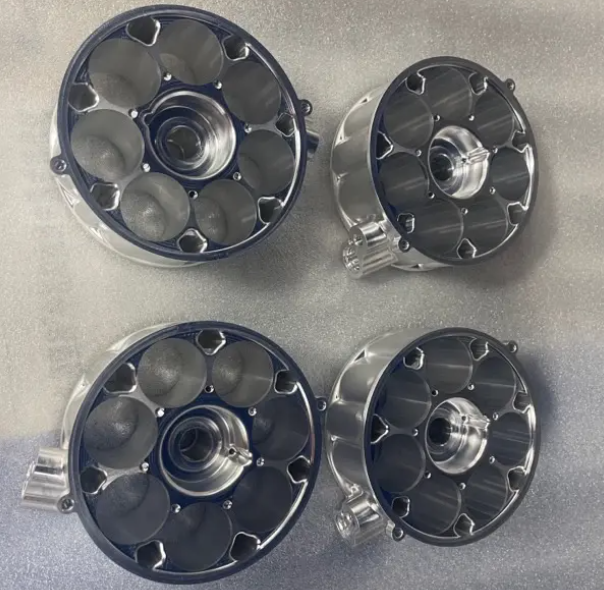
Material Behavior and Its Influence on High-Volume Machining
Different materials react differently under continuous machining. Stable processes account for material-specific behavior, including microstructure, hardness, and thermal properties.
Aluminum Alloys
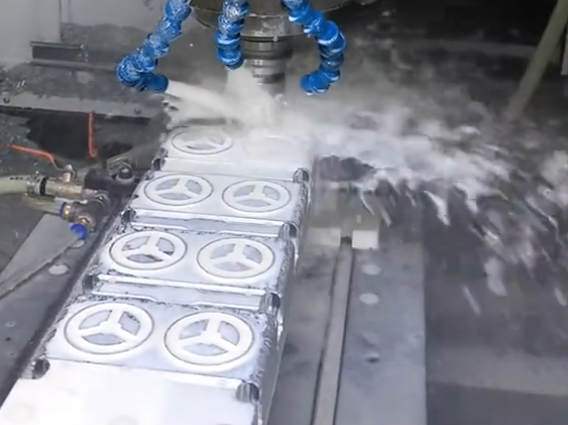
Aluminum alloys allow high cutting speeds and feed rates, with typical cutting speeds ranging from 300 to over 1,000 m/min depending on alloy and tooling. However, challenges include built-up edge formation, chip evacuation, and maintaining surface finish at high material removal rates.
Carbon and Alloy Steels
Steels generally require lower cutting speeds and generate higher cutting forces and heat. Process stability depends on appropriate coolant application, consistent tool wear monitoring, and managing thermal growth of both part and machine.
Stainless Steels and Superalloys
These materials are prone to work hardening and produce higher cutting temperatures. High-volume processes in these materials pay close attention to:
- Coolant delivery and pressure
- Optimized chip thickness
- Controlled tool engagement to avoid excessive heat
For superalloys, tool life can be relatively short, so tool change policies and standardization become critical to avoid unplanned downtime and dimensional drift.
Workholding, Datum Strategy, and Repeatability
Consistent location and orientation of the workpiece is fundamental to high-volume dimensional control.
Datum Selection
Primary, secondary, and tertiary datums must be defined in alignment with functional requirements and chosen to minimize sensitivity to small variations in raw material or casting geometry.
Datums should:
- Be accessible in the chosen setup
- Have enough area and stiffness to avoid deflection
- Be stable over the part’s temperature range
A consistent datum scheme is maintained across all operations to minimize re-location error.
Fixture Design and Validation
Fixtures are validated for:
- Repeatability: typically measured over multiple clamp/unclamp cycles
- Deformation: checking part geometry before and after clamping
- Clamping force range: ensuring adequate retention without distortion
Measurement of reference features across repeated loadings gives quantitative data on fixture repeatability, commonly targeting a variation well below the tightest critical tolerance.
Tool Life, Wear Control, and Tool Management
Tool wear is one of the main sources of dimensional drift in long production runs. High-volume machining requires systematic tool management.
Defining Tool Life in Measurable Terms
Tool life must be expressed as an objective metric rather than a subjective assessment. Common definitions include:
- Maximum flank wear land width (for example, 0.2 mm)
- Maximum increase in cutting forces or spindle load
- Maximum increase in surface roughness (Ra)
The corresponding number of parts, cutting time, or length of cut is recorded and used to set conservative tool change intervals.
Tool Offsets and Compensation
Offsets are adjusted based on measured deviations. In high-volume environments, compensation rules are documented, for example:
- If dimension X exceeds nominal by more than 0.005 mm, reduce tool length offset by 0.003 mm and recheck after 3 parts.
Such rules minimize guesswork and reduce risk of overcorrection, which can cause parts to shift between upper and lower tolerance limits.
Presetting and Tool Identification
Tool presetters measure tool length and diameter before tools are loaded into the machine. Pre-measured tools reduce setup time and avoid manual offset entry errors.
Tool identification can rely on barcodes, RFID tags, or structured pocket numbering in the tool magazine. The objective is to ensure the CNC program uses the correct tool with known geometry and life data.
Thermal Effects and Long-Run Stability
Extended CNC operation introduces thermal gradients in the machine, fixtures, and parts. These gradients can cause dimensional shifts, especially for tight tolerances and high material removal rates.
Machine Warm-Up and Temperature Control
Common practices include:
- Warm-up cycles for spindles and axes before production
- Coolant temperature control to a defined range
- Environmental control of shop temperature
Temperature compensation features in CNC control can be used where appropriate, but they require validation with real measurements.
Part Temperature and Measurement
Part dimensions measured immediately after machining may differ from those after cooling. High-volume processes specify:
- Waiting time or cooling method before measurement
- Measurement temperature range
- Environmental conditions around inspection equipment
Dimensional trends over shifts and days are monitored to detect temperature-related drift.
Programming Practices for High-Volume CNC Machining
CAM programming impacts cycle time, reliability, and maintainability of the process. Stable high-volume programs tend to favor clarity and predictability over aggressive but fragile optimization.
Toolpath Strategies
For roughing, constant engagement toolpaths can reduce load spikes on tools and spindles. For finishing, consistent stepovers and stepdowns improve surface quality.
Safe retracts, controlled entry and exit moves, and avoidance of abrupt direction changes reduce risk of vibration and surface defects.
Template and Library Use
Standardized tool libraries, feeds, and speeds for specific materials help enforce consistent process behavior across multiple parts and programs.
Template operations (for example, standard drilling sequences, pocketing strategies) reduce the chance of programming mistakes and make it easier to apply lessons learned across new components.
Error-Proofing in Programs
Programs can include checks such as:
- Probing cycles to confirm part presence and orientation
- Tool length and diameter checks before critical operations
- Automatic alarms when offsets exceed predefined safe ranges
These controls help detect deviations before they translate into scrap or rework.
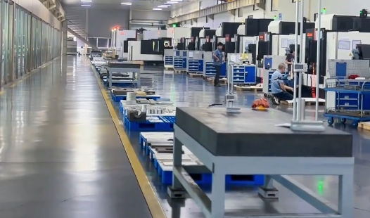
Inspection, SPC, and Quality Assurance in Production
High-volume CNC machining uses structured inspection plans and statistical process control to maintain quality over time.
Control Plans and Sampling
Control plans define:
- Which dimensions are critical, major, and minor
- Measurement methods and gauges used
- Sampling frequency (for example, every 10th part, every hour, per lot)
- Reaction plans when measurements approach limits
Critical features may be checked at higher frequency, sometimes on 100% of parts for safety-critical applications.
SPC Charts and Reaction Rules
X-bar and R charts or individual/moving range charts monitor dimension trends. Common reaction rules include:
- Adjusting offsets when the process mean shifts by a defined amount
- Stopping machines when points fall outside control limits
- Investigating causes of non-random patterns such as runs or cycles
These rules are documented and integrated into operator instructions, so that responses to variation are consistent and auditable.
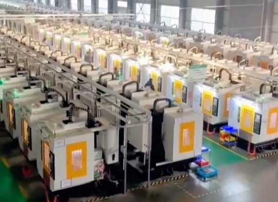
Automation, Palletization, and Lights-Out Operation
Automation increases throughput and reduces labor per part but adds requirements for system stability and monitoring.
Pallet Systems and Multi-Machine Cells
Pallet changers and pallet pools allow setups outside the machine, reducing spindle idle time. Pallet codes and standardized zero-point clamping systems help maintain repeatability across multiple machines.
In multi-machine cells, scheduling rules define how pallets move between machines. Tool and offset consistency across machines becomes important when parts are processed in more than one CNC during their routing.
Unattended and Lights-Out Machining
Unattended operation requires robust detection of abnormal conditions. Common elements include:
- Tool breakage detection using load monitoring or in-cycle probing
- Coolant level and pressure monitoring
- Chip conveyor and filter status monitoring
Tool life limits and offset ranges are set conservatively so that the process can run through the unattended period without exceeding limits.
Common Issues in High-Volume CNC Machining
Some problems appear more frequently when volumes are high and machines run near continuously. Recognizing them helps in designing preventive measures.
Dimensional Drift Over Time
Gradual drift can result from tool wear, thermal growth, fixture wear, or changes in raw material. Countermeasures include:
- Scheduled offset checks tied to part counts
- Defined tool life limits with planned changes
- Periodic fixture inspection and maintenance
SPC charts are useful for distinguishing random variation from systematic drift.
Unexpected Tool Breakage
Tool breakage causes immediate scrap, potential machine damage, and downtime. It is often associated with chips packing in deep cavities, incorrect coolant direction, or occasional hard spots in material.
Detection methods can include spindle power monitoring, vibration thresholds, or in-process probing. Parameters such as feed per tooth and ramp-in strategies are adjusted to keep load spikes within a safe range.
Variation Between Machines
When the same part is produced on multiple CNCs, differences in machine kinematics, error compensation, or thermal behavior may cause dimensional differences. To mitigate this, processes are validated on each machine, and machine-specific offsets or correction tables may be applied.
Documentation, Standardization, and Training
Documentation and consistent training are required to maintain process stability as personnel and production schedules change.
Standard Work Instructions
Instructions typically cover:
- Setup steps and fixture clamping sequence
- Tool list with corresponding offsets and pocket positions
- Offset adjustment rules and allowable ranges
- Inspection steps, gauges, and frequencies
These documents are controlled, updated after engineering changes, and accessible at the workstation.
Change Management
Any change to tooling, cutting parameters, fixtures, or inspection must be evaluated before implementation in production. A standard change process often requires:
- Risk assessment
- Trial run and capability check
- Update of documentation and training of operators
This prevents well-intentioned but unvalidated modifications from reducing process capability.
Key Performance Metrics for High-Volume CNC Machining
Establishing objective metrics enables consistent evaluation and improvement of production processes.
| Metric | Definition | Typical Use |
|---|---|---|
| Cycle time | Total time per part including cut, non-cut, and handling | Capacity planning, scheduling, performance tracking |
| OEE | Availability × Performance × Quality | Overall equipment productivity assessment |
| Cp, Cpk | Process capability indices for key dimensions | Validation of process stability and tolerance fit |
| Scrap rate | Scrap parts divided by total produced parts | Quality performance and cost analysis |
| Rework rate | Reworked parts divided by total produced parts | Detection of latent quality and process problems |
| Tool cost per part | Total tool cost divided by number of parts produced | Optimization of tooling strategy and parameter choice |
| Mean time between failures (MTBF) | Average time between machine or process interruptions | Maintenance planning and reliability engineering |
FAQ: High-Volume CNC Machining
What qualifies as high-volume CNC machining?
High-volume CNC machining typically refers to production runs where repeatability, process stability, and throughput matter more than setup flexibility. This often starts at tens of thousands of parts and scales into hundreds of thousands or millions, depending on part complexity and tolerance requirements.
When does CNC machining stop being cost-effective at high volumes?
CNC remains cost-effective as long as cycle time, tool life, and automation are optimized. However, for very simple geometries and extremely high volumes, dedicated tooling or alternative processes may offer lower unit costs.
What are the biggest challenges in high-volume CNC machining?
The most common challenges include tool wear variability, thermal drift, fixture consistency, and maintaining tight tolerances over long production runs. These issues tend to emerge only after extended runtime, not during pilot production.
How do I know if a CNC process is ready for high-volume production?
A process is ready for high-volume production when it has stable, documented cutting parameters, validated fixtures and tooling, and quantified process capability. Capability studies for critical dimensions should show Cp and Cpk values at or above the required targets, typically 1.33 or higher. A control plan, sampling strategy, and reaction rules should be defined, and a pilot run should confirm that cycle time, scrap rate, and tool life are consistent with production requirements.
What are common mistakes companies make in high-volume CNC machining?
Common mistakes include underestimating tool wear, relying too heavily on final inspection, and assuming pilot results will scale linearly. These errors often lead to unexpected cost and quality issues.
