
A grease manifold block is a central distribution component used in automatic and manual lubrication systems to deliver controlled amounts of grease from one or more inlets to multiple lubrication points. It consolidates piping, improves control of lubricant flow, and helps ensure that critical machine elements such as bearings, gears, slides, and chains receive adequate lubrication.
Definition and Basic Function of a Grease Manifold Block
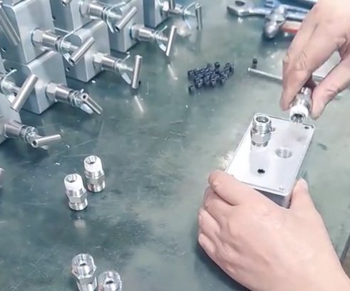
A grease manifold block is a machined metal body containing a network of internal channels that route grease from a pump or reservoir inlet to several outlet ports. Each outlet is typically connected via tubing or hoses to a lubrication point or to secondary distribution devices.
The primary functions are:
- Splitting a grease supply line into multiple outlets
- Balancing or controlling grease delivery to separate points or zones
- Providing convenient connection and isolation points for maintenance
Depending on design, a manifold can be a simple distribution block or an integrated valve assembly that meters and monitors grease flow to each outlet. Grease manifolds are widely used in centralized lubrication systems in industrial, mobile, marine, and process equipment.
Working Principle of Grease Manifold Blocks
Grease manifold blocks operate by guiding pressurized lubricant through internal passages and distributing it to outlet ports under the pressure produced by a grease pump or manual grease gun. The exact working principle depends on the type of manifold.
Simple Distribution Manifold Principle
In a basic distribution manifold:
- Grease enters the manifold through one or more inlet ports.
- Internal bores or cross-drillings connect the inlet passages to each outlet port.
- System pressure forces grease simultaneously toward all open outlets.
In such designs, the amount of grease delivered to each point depends on factors like line resistance, restriction fittings, and the duty cycle of the pump. There is no internal metering element inside the block; it acts as a structural and connection component.
Metering and Progressive Manifold Principle
More advanced grease manifold blocks incorporate metering pistons and check mechanisms. A common example is the progressive divider valve style, where the manifold consists of a stack of metering sections with internal spool pistons:
- Grease enters the inlet section and pressurizes the first piston chamber.
- The piston stroke displaces a defined volume of grease to an outlet port.
- Only after one piston completes its stroke does the next piston in sequence move.
- This progressive sequencing continues until all pistons complete their strokes.
The fixed displacement per piston stroke provides a predetermined grease volume per outlet or per cycle. By monitoring a cycle indicator or sensor, operators can confirm that lubrication is actually occurring. Progressive manifolds stop if any outlet is blocked, making troubleshooting more straightforward.
Multi-line and Zoning Manifold Principle
In multi-line manifolds, multiple independent outlets are supplied directly by a pump or through check valves and relief valves. Each outlet can be configured for:
- Direct feed to a lubrication point
- Supply to a secondary progressive divider valve
- Feed to a separate lubrication zone or circuit
By adjusting line diameters, restrictions, or separate metering devices, each outlet may serve components with different lubrication demands. Manifolds used for zoning often incorporate ball valves or shutoff plugs in each port to allow selective isolation.
Key Components and Construction Features
While designs vary by manufacturer and application, most grease manifold blocks include several common construction features.
Body and Internal Channels
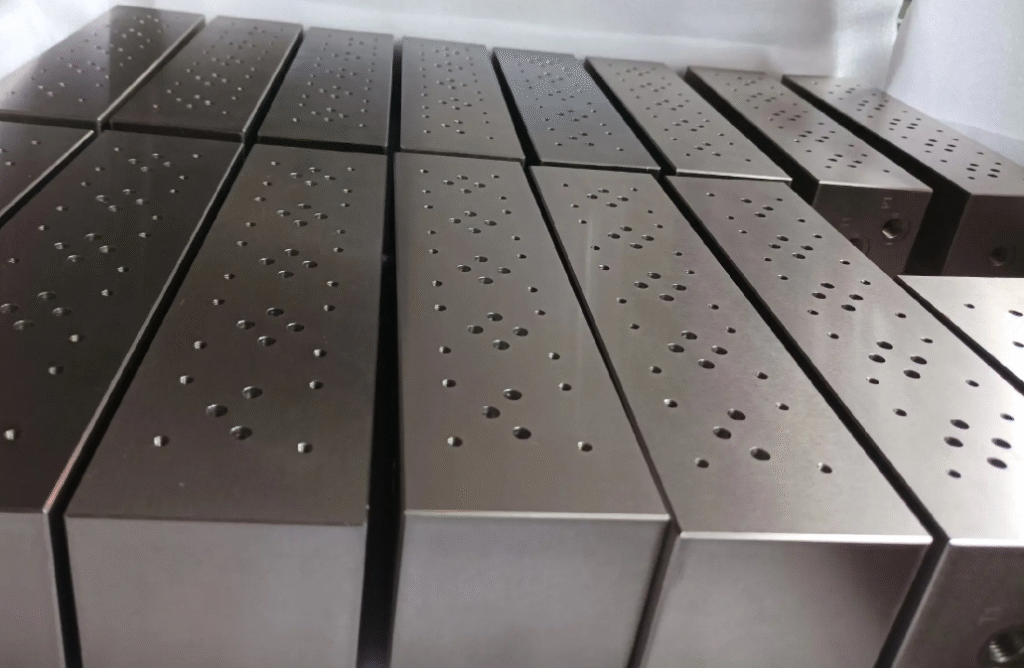
The manifold body is usually machined from a solid metal block. Internal channels are created by drilling and cross drilling, then plugging or sealing intersecting holes. The geometry of these passages is critical for ensuring equal or controlled flow across outlets and maintaining allowable pressure drops.
The body may include:
- Primary inlet bores
- Distribution galleries feeding outlet lines
- Cross channels for pressure balancing
- Plugged ports to allow different configuration options
Ports, Threads, and Sealing
Inlet and outlet ports are threaded to accept fittings or tube connectors. Common thread standards include NPT, BSPP, BSPT, and metric threads. Sealing at these ports may be achieved by tapered threads, bonded washers, O-ring face seals, or compression fittings.
Internal closure plugs are often used to close cross drillings. These may be screw plugs with thread sealant, press-fit plugs, or welded closures, depending on pressure rating and leakage risk.
Valves, Metering Elements, and Indicators
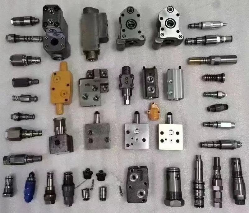
More complex manifold blocks can integrate:
- Check valves to prevent backflow between outlets
- Metering pistons or orifice inserts for metered dispensing
- Relief valves to protect against overpressure
- Shutoff valves for isolation of individual lines
- Cycle indicators or proximity sensors for progressive systems
These elements allow the manifold to perform multiple functions in a compact assembly, reducing external piping and separate components.
Types of Grease Manifold Blocks
Grease manifold blocks are available in several types based on function, complexity, and application.
Simple Distribution Blocks
Simple distribution manifolds, sometimes called junction blocks or terminal blocks, are plain bodies with one or more inlets and multiple outlets. They do not meter flow but serve to:
- Split a single grease line into a number of discrete lines
- Provide convenient grouping of lubrication lines
- Reduce the number of individual fittings at the pump outlet
These blocks are commonly used in small systems, manual lubrication setups, or as secondary distribution near clusters of lubrication points.
Progressive Divider Valve Manifold Blocks
Progressive divider valves are highly structured manifold assemblies where each section meters a fixed volume. Features typically include:
- Stackable metering sections with a common inlet
- Predetermined discharge volume per outlet per cycle
- Option to bridge or combine outlets to increase volume
- Cycle indicator pins or electrical sensors
These manifolds are widely used in centralized automated systems for machinery where equal or proportional distribution and positive monitoring are required.
Multi-line and Parallel Feed Manifolds
Multi-line manifolds are used where a pump supplies several outlets in parallel, each acting as an individual line to a lubrication point or to a secondary distributor. They can be used with multi-line pumps or with a single pump feeding a manifold with check valves and relief valves.
These systems are suitable for large machines where individual lubrication lines must cover long distances or where different components require independent timing or quantity adjustments.
Custom and Modular Manifold Blocks
Custom manifolds are designed for specific machines or systems. Characteristics may include:
- Machining to fit into limited envelope spaces
- Integration of multiple circuits or zones in one block
- Combination of grease distribution with hydraulic or pneumatic functions
- Dedicated mounting features and interface surfaces
Modular manifolds allow users to add or remove sections, change outlet quantities, or adapt to changing system layouts without replacing the entire block.
Materials and Surface Treatments
The selection of material and surface finish is important for durability, compatibility with lubricant, and environmental resistance.
| Material | Typical Applications | Advantages | Considerations |
|---|---|---|---|
| Carbon steel (uncoated) | Indoor machinery, low-corrosion environments | High strength, cost-effective | Requires clean conditions or protective coating |
| Zinc-plated carbon steel | General industrial, mobile equipment | Improved corrosion resistance | Plating thickness and quality affect long-term performance |
| Stainless steel (e.g., 304, 316) | Food, pharmaceutical, marine, corrosive environments | High corrosion resistance, cleanability | Higher cost, may require suitable fittings to avoid galvanic issues |
| Aluminum alloy | Weight-sensitive or mobile machinery | Low weight, good machinability | Limited maximum pressure vs. steel, needs anodizing or coating |
| Brass | Special applications, moderate corrosion risk | Good machinability, corrosion resistance | Higher material cost, not preferred at very high pressures |
Surface treatments can include zinc plating, nickel plating, anodizing (for aluminum), or passivation (for stainless steel). In applications with sanitary requirements, smooth surfaces and minimal dead zones are important to prevent contamination.
Typical Technical Parameters and Ratings
Grease manifold blocks are specified by several technical parameters that must match the lubrication system design.
Pressure Rating
Working pressure and maximum permissible pressure are key parameters. Grease systems may operate at pressures ranging from 50 bar to over 400 bar depending on pump type and line length. Manifold blocks must be rated above the maximum system pressure, taking into account pressure peaks during cold starts or blockages.
For example, typical nominal ratings may include:
- Working pressure: 100–315 bar for many industrial manifolds
- Maximum pressure: up to 400–500 bar for heavy-duty progressive manifolds
Exact values depend on material, wall thickness, and internal design.
Number of Outlets and Flow Capacity
Manifolds are available with different numbers of outlets, such as 2, 4, 6, 8, 10, or more. Progressive manifolds may allow combining outlets to achieve higher discharge volume per lubrication point.
Flow capacity is determined by internal channel dimensions and outlet arrangements. Manufacturers typically provide:
- Minimum and maximum outlet volume per cycle (e.g., 0.01–2.0 cm³ per cycle)
- Maximum total flow per minute at a given pressure
- Recommended lubricant viscosity range
Operating Temperature and Lubricant Compatibility
Grease manifold blocks must operate reliably across the full temperature range where the machine is used. Typical operating temperature ranges depend on seals and materials but are often around:
- –20 °C to +80 °C for standard systems
- Extended ranges available with special seals and materials
The block material and internal components must be compatible with the selected grease, including its base oil type, thickener, and additives. Most metallic manifolds are suitable for standard mineral and synthetic greases, but seal materials must be considered where elastomeric components are present.
Port Sizes, Thread Types, and Dimensions
Port sizes typically range from small threads for outlet lines (e.g., M8x1, M10x1, 1/8" NPT) to larger inlets (e.g., 1/4" NPT, G 3/8). Manifold dimensions are chosen based on mounting constraints and the required number of outlets.
| Parameter | Typical Values | Notes |
|---|---|---|
| Inlet port thread | G 1/4, G 3/8, 1/4" NPT, 3/8" NPT | Depends on pump outlet size and regional standards |
| Outlet port thread | M8x1, M10x1, G 1/8, 1/8" NPT | Selected to match tubing and fittings |
| Number of outlets | 2–24+ (progressive stacks can be extended) | Adjustable through modular sections in some designs |
| Mounting hole spacing | Varies by model, often standardized for product family | Important for replacement and retrofitting |
| Outlet volume (progressive type) | Approx. 0.01–2.0 cm³ per outlet per cycle | Dependent on metering section size |
Applications and Use Cases
Grease manifold blocks are used wherever multiple lubrication points must be supplied reliably and efficiently.
Industrial Machinery
In industrial environments, manifolds are installed on:
- Conveyors and material handling systems
- Presses, stamping and forming equipment
- Machine tools, including spindle and slideway lubrication
- Paper machinery, steel mills, and process lines
They help centralize lubrication, reduce manual greasing tasks, and control lubricant consumption in large plants.
Mobile Equipment and Off-highway Machinery
Excavators, loaders, cranes, agricultural machines, and mining equipment often use centralized grease systems with manifold blocks to service pins, bushings, bearings, and joints. The manifold may be located on the frame or near joint clusters to shorten line lengths and protect components from dirt and physical damage.
Energy, Marine, and Process Industries
Wind turbines, hydroelectric equipment, shipboard machinery, and various process industry applications make use of grease manifolds for lubrication of slew bearings, gear meshes, and critical rotating or sliding elements. In these applications, reliability and corrosion resistance are especially important.
System Design Considerations for Manifold Selection
Selecting the correct grease manifold block requires aligning technical capabilities with system requirements.
Matching System Pressure and Flow
The manifold must be rated for the maximum pump pressure and the overall hydraulic characteristics of the system. Designers should consider:
- Maximum operating pressure and potential pressure peaks
- Line length and pressure drop between manifold and lubrication points
- Viscosity and pumpability of the grease at low temperature
Progressive manifolds may require a minimum pressure to complete the piston cycle, and systems should be designed to maintain adequate pressure across all outlets.
Number and Location of Lubrication Points
The total number of points, their grouping, and their distance from the pump are key factors. For widely distributed lubrication points, multiple manifolds may be preferable to one large block, reducing line length and improving response time.
Designers often group lubrication points with similar lubrication intervals and quantities on the same manifold or zone to simplify control and maintenance.
Lubricant Type and Environmental Conditions
Grease type (NLGI grade, base oil viscosity, thickener), ambient temperature, and exposure to water or contaminants influence manifold choice and material selection:
- High-viscosity or high NLGI grade greases may require larger passage sections and higher pump capacities.
- Outdoor or marine applications may require stainless steel or special coatings.
- Food and pharmaceutical applications may demand stainless steel manifolds and NSF H1-approved grease.
Integration with Controls and Monitoring
Automated systems often monitor lubrication performance. Progressive manifolds, in particular, can be equipped with cycle switches or sensors to provide feedback to a controller. Designers should determine whether:
- Cycle counting or stroke monitoring is needed
- System alarms should trigger if lubrication does not occur
- Integration with PLC or condition monitoring systems is required
Installation Guidelines and Best Practices
Proper installation is essential for reliable operation of grease manifold blocks.
Mounting Orientation and Support
Manifolds should be mounted on rigid structures using the designated mounting holes. Orientation should follow manufacturer recommendations, particularly for progressive divider valves to allow proper venting and drainage. Adequate support must be provided for connected tubes and hoses to prevent mechanical stress on ports.
Tubing, Hoses, and Fittings
The choice of tubing or hoses influences pressure capability and long-term durability. Common choices include:
- Steel tubing for fixed industrial installations
- Flexible hoses for moving or vibrating components
- Polymer tubing for lower-pressure or protected environments
Bend radius, clamping, and routing must be designed to avoid kinks, fatigue, and damage. Thread sealants and torque values should follow manufacturer specifications to prevent leaks and thread damage.
Contamination Control and Cleanliness
Before installation, all ports, plugs, and fittings should be cleaned to avoid introducing foreign particles. It is good practice to:
- Keep protective caps in place until connection
- Flush lines where contamination risk is high
- Use filters or strainers at the pump outlet when recommended
Contamination can block metering passages and cause uneven lubrication or component failure.
Operation, Maintenance, and Troubleshooting
Regular inspection and maintenance of grease manifold blocks support consistent lubrication performance and extend equipment life.
Routine Inspection and Functional Checks
Maintenance tasks may include:
- Visual inspection for leaks, corrosion, or mechanical damage
- Checking outlet indicator pins on progressive manifolds
- Verifying that grease appears at lubrication points during pump operation
Where sensors are installed, verifying correct signaling and response to alarms is important.
Cleaning, Blockage Removal, and Component Replacement
Grease passages can become blocked by hardened grease, contamination, or damage. Troubleshooting steps may involve:
- Isolating the suspected outlet and checking for flow
- Removing outlet fittings and verifying output directly at the manifold
- Flushing or replacing suspect lines and fittings
With progressive manifolds, a blocked outlet will usually stop the entire divider sequence. Identifying which section has stalled can help pinpoint the affected point. Some designs allow cleaning, while others require replacement of the metering section.
Common Issues and Practical Considerations
Users may face challenges such as:
- Under-lubrication of distant points due to pressure loss
- Over-lubrication if outlet volumes are not matched to bearing requirements
- Leakage at fittings that loosens mounting or causes contamination
These issues can often be addressed by reviewing system design, adjusting outlet combinations or restrictions, and ensuring the manifold is mounted and supported correctly.
Advantages of Using Grease Manifold Blocks
Grease manifold blocks bring several advantages compared with individual, independent lubrication points.
Centralized Control and Reduced Maintenance
By consolidating lubrication into a centralized or semi-centralized system, operators can:
- Reduce the time and labor required for manual greasing
- Improve consistency of lubrication intervals and quantities
- Monitor lubrication status from a single access point
In many applications, this leads to improved bearing life and fewer unscheduled stoppages.
Compact and Organized Piping Layouts
Manifold blocks help organize tubing and hoses, reducing the number of random lines across a machine and simplifying routing. This improves accessibility, makes troubleshooting easier, and reduces the risk of damaged lines.
Improved Reliability and Process Control
By using metering and progressive manifold systems, the lubricant volume delivered to each point can be controlled and verified. This improves reliability in critical applications, where insufficient or excessive lubrication leads to wear, overheating, or safety risks.
FAQ: Grease Manifold Blocks
What is a grease manifold block?
A grease manifold block is a distribution component used in centralized lubrication systems to evenly distribute grease from a single inlet to multiple outlet lines.
What are grease manifold blocks used for?
They are commonly used in industrial machinery, construction equipment, mining equipment, and automated lubrication systems to ensure consistent and efficient grease delivery to multiple lubrication points.
Are grease manifold blocks compatible with different grease types?
Yes, they are compatible with most standard lubricating greases, including lithium-based, calcium-based, and synthetic greases, provided the grease consistency matches system specifications.
What is the difference between a simple manifold block and a progressive divider valve?
A simple manifold block acts as a junction that splits the grease supply into multiple outlets without internal metering. A progressive divider valve, on the other hand, contains internal pistons that meter a fixed volume of grease to each outlet in sequence. Progressive valves provide defined output per cycle and allow functional monitoring, while simple blocks mainly provide structural distribution.
