
Cryogenic machining is a metal cutting process in which extremely low temperature media, typically liquid nitrogen (LN₂) or carbon dioxide (CO₂), are applied directly to the cutting zone to control heat generation, tool wear, and workpiece surface integrity. It is used in turning, milling, drilling, grinding, and other subtractive manufacturing operations on difficult-to-cut materials such as titanium alloys, nickel-based superalloys, hardened steels, and certain composites.
Fundamentals of Cryogenic Machining
Cryogenic machining integrates conventional chip formation mechanics with controlled low-temperature cooling of the tool–chip–workpiece interface. Instead of or in addition to flood cutting fluids, a cryogenic medium is delivered in liquid or solid–gas form to the cutting zone, rapidly absorbing heat and lowering the local temperature.
Cryogenic Media and Temperature Ranges
The most widely used cryogens in machining are:
- Liquid nitrogen (LN₂): boiling point approximately −196 °C (77 K)
- Liquid or solid CO₂ (dry ice): sublimation around −78.5 °C (194.7 K)
LN₂ provides the lowest temperatures and is chemically inert and non-flammable. CO₂ offers higher temperature but easier handling in some environments and can be supplied from pressurized cylinders with integrated expansion systems.
Mechanism of Heat Removal
During metal cutting, plastic deformation of the shear zone and friction at tool–chip and tool–workpiece interfaces generate heat. Cryogenic media remove heat by:
- Latent heat absorption during evaporation (LN₂) or sublimation (CO₂)
- Convective heat transfer from surfaces exposed to the cold gas jet
- Reduction of friction coefficients at the tool–chip interface due to lower temperature and reduced adhesion
The predominant heat removal occurs at the tool–chip interface in external turning and face milling, and at the cutting edge and flute surfaces in drilling and end milling.
Effect on Workpiece and Tool Materials
Cooling affects both the mechanical properties of the workpiece and the behavior of cutting tool materials:
Workpiece materials at low temperature can show increased hardness and strength, reduced ductility, and altered strain hardening behavior. For some alloys, this helps stabilize chip formation and reduce built-up edge, while for others it can increase cutting forces.
Tool materials generally benefit from reduced diffusion wear, oxidation, and thermal softening when cooled. Cemented carbides, ceramics, cermets, PCBN, and PCD respond differently to rapid cooling; selection and coating design must take thermal shock resistance into account.

Comparison with Conventional Cooling and Dry Machining
Cryogenic machining is often compared against dry cutting and conventional flood or minimum quantity lubrication (MQL) conditions in terms of tool life, cutting forces, surface integrity, and chip formation.
| Aspect | Dry Machining | Flood / Emulsion Cooling | Cryogenic Machining (LN₂ / CO₂) |
|---|---|---|---|
| Heat removal capacity | Low, mainly by chip evacuation and natural convection | Moderate to high via convection and lubricant flow | Very high via phase change and cold gas convection |
| Tool wear rate | Often high, dominated by adhesion and oxidation | Reduced compared with dry, lubricant-dependent | Significantly reduced diffusion/oxidation wear; flank and crater wear minimized in many applications |
| Surface integrity | Risk of high tensile residual stress and higher roughness | Improved vs dry, but affected by thermal gradients | Potential for compressive residual stress, low white layer, enhanced surface finish |
| Coolant management | Minimal, primarily chip handling | Requires filtration, disposal, and maintenance | Requires cryogen storage and venting; no liquid waste |
| Occupational exposure | Dust and chips only | Exposure to cutting fluid aerosols and additives | Exposure to cold gas and oxygen displacement risks, but no oil mist |
Cryogenic Media Types and Delivery Methods
The configuration of the cryogenic supply system and the way the medium is delivered to the cutting zone strongly influence process results.
Liquid Nitrogen Systems
Typical LN₂ setups include:
- Dewar or bulk storage tank, insulated and pressure-controlled
- Vacuum-insulated transfer lines to the machine
- Control valves and flow meters to regulate LN₂ flow rate
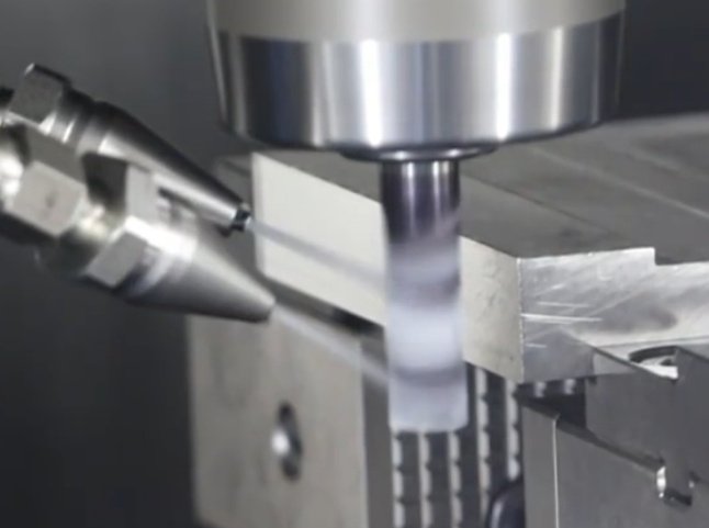
- Nozzles integrated in tool holders, spindle, or external fixtures
LN₂ can be delivered as a liquid jet, a two-phase mixture, or fully vaporized cold gas. Internal delivery through the tool or spindle allows more accurate targeting of the cutting edge.
Carbon Dioxide Systems
CO₂ cooling systems usually operate with high-pressure cylinders or centralized supply:
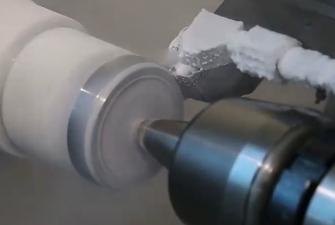
CO₂ is expanded through a nozzle to form a mixture of cold gas and solid particles (dry ice snow). The impact of this mixture on the tool–chip interface provides intensive localized cooling. CO₂ systems can be combined with small amounts of lubricant (cryo-MQL) to provide both cooling and lubrication.
Delivery Configurations
Common delivery arrangements include:
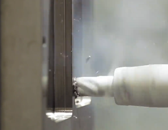
External nozzle delivery: Nozzles mounted near the cutting zone, often adjustable for direction and distance. This configuration is easier to retrofit but can be less precise in reaching the exact interface region.
Internal through-tool delivery: Channels within the tool holder and tool body guide the cryogen to the rake face near the cutting edge. This improves cooling efficiency and reduces consumption but requires specialized tooling and sealing.
Through-spindle delivery: Used mainly in milling and drilling; cryogen flows through the spindle and then through the tool or exits near it. This configuration supports high rotational speeds and complex 3D toolpaths.
Cutting Mechanics and Material Removal Behavior
Low temperature affects chip formation, friction, and force patterns in cryogenic machining.
Chip Formation and Morphology
For many alloys, cryogenic cooling reduces built-up edge formation by decreasing adhesion at the tool–chip interface. Chips may become more segmented or serrated as the material’s ductility decreases with temperature. In titanium and nickel-based alloys, cryogenic conditions often stabilize adiabatic shear band formation, producing regular segmented chips and more consistent cutting forces.
Cutting Forces and Power Consumption
The effect on cutting forces depends on the balance between increased material strength at lower temperature and improved lubrication-like effects from reduced adhesion:
In hardened steels, forces can increase slightly due to higher flow stress, but the lower friction and better wear control may maintain or even reduce net cutting power over a tool’s life. In titanium alloys, cryogenic cooling can reduce average cutting forces by limiting adhesion and built-up edge, especially when combined with optimized cutting parameters.
Tool Materials, Coatings, and Life in Cryogenic Machining
Tool life is one of the central metrics in evaluating cryogenic machining performance. Understanding how cryogenic conditions interact with tool substrates and coatings is critical.
Carbide Tools
Cemented carbide is widely used in cryogenic turning and milling. Under cryogenic conditions:
Lower temperatures reduce diffusion wear and minimize chemical interaction between tool and workpiece. Crater wear depth tends to be reduced, and flank wear progression slows, especially in high-temperature alloys. However, thermal shock from rapid cooling and intermittent contact (e.g., milling) must be managed with suitable grade selection and edge preparation.
Coatings for Cryogenic Machining
Typical coatings include TiAlN, AlTiN, AlCrN, and multi-layer nano-structured systems optimized for high-temperature stability. In cryogenic machining:
Coatings remain cooler, so oxidation-based self-lubricating mechanisms are less active, while mechanical integrity is improved and coating softening is reduced. Coating architecture must balance hardness, adhesion to substrate, and resistance to micro-cracking under thermal cycling. PVD coatings with high adhesion and fine columnar structure are commonly used.
Ceramic, PCBN, and PCD Tools
Advanced materials such as ceramics and PCBN benefit from reduced thermal load, which limits thermal cracking and diffusion. For hardened steels and cast irons, cryogenic cooling can be applied selectively to maintain a working temperature window that avoids brittle fracture but reduces tool tip temperatures compared with dry cutting. PCD tools in aluminum and composites benefit primarily from lower adhesive wear and better control of chip evacuation.
Process Parameters and Optimization
Cryogenic machining requires coordinated selection of cutting parameters and cryogen supply variables. Key variables include cutting speed, feed, depth of cut, cryogen flow rate, pressure, nozzle positioning, and timing.
Cutting Parameters
Typical ranges vary by material and tool, but general considerations are:
Cutting speeds can often be maintained or increased relative to flood cooling due to better tool temperature control, especially in high-temperature alloys. Feed per tooth or per revolution can be chosen to ensure adequate chip thickness for effective heat removal via chips. Depth of cut is often maintained at production levels, as cryogenic cooling primarily addresses temperature rather than structural stiffness.
Cryogen Flow Rate and Pressure
Flow rate must be sufficient to achieve stable low-temperature conditions at the cutting edge but not so high as to cause unnecessary consumption or interference with chip evacuation and measurements. For LN₂ systems, flow rates in the range of a few liters per minute are common for external nozzle applications, while through-tool systems can be optimized around smaller, more efficient flows. CO₂ systems are typically specified in kg/h or g/s, with values set to ensure continuous coverage of the cutting zone.
Nozzle Position and Orientation
Nozzle angle, distance from the cutting edge, and relative motion with respect to the toolpath determine cooling efficiency. In turning, a nozzle aimed at the rake face near the primary shear zone often yields strong benefits. In milling, multiple nozzles may be needed to cover entry and exit regions of the cutting edge and to handle changing engagement conditions.
Workpiece Materials and Application Domains
Cryogenic machining is particularly relevant for metals and alloys that generate high cutting temperatures or cause rapid tool wear under conventional conditions.
Titanium Alloys
Titanium alloys, such as Ti-6Al-4V, have low thermal conductivity and high chemical reactivity, leading to intense localized heating at the tool–chip interface. Cryogenic cooling reduces interface temperature, adhesion, and the tendency for built-up edge formation. This can extend tool life and improve surface quality at industrially relevant cutting speeds in turning and milling.
Nickel-Based Superalloys
Alloys such as Inconel 718 and other Ni-based superalloys maintain high strength at elevated temperatures and are prone to work hardening. Cryogenic machining assists by reducing the thermal load on the cutting edge and limiting diffusion wear and notch wear at the depth-of-cut line. It is commonly applied in aerospace engine component machining in finishing and semi-finishing operations.
Hardened Steels
For hardened bearing steels and tool steels with hardness above 50 HRC, cryogenic turning and milling can improve surface integrity while controlling tool wear. In some cases, cryogenic cooling changes the balance between mechanical and thermal damage to the surface, leading to lower white layer thickness and more favorable residual stress profiles.
Aluminum Alloys and Composites
In aluminum machining, cryogenic cooling is less critical for temperature control but can reduce adhesion on tools and improve chip evacuation in deep hole drilling. In composite machining, such as CFRP, local cooling can influence matrix behavior and contribute to reduced smearing and better hole quality, provided that brittle fracture modes are controlled.
Surface Integrity and Metrology
Surface integrity is a central quality criterion in high-performance machining, affecting fatigue life, corrosion resistance, and dimensional stability.
Surface Roughness
Cryogenic cooling can lead to lower average roughness (Ra) by stabilizing chip formation, reducing built-up edge, and preventing smearing or tearing of the surface. The improvement depends on tool geometry, cutting conditions, and the type of cryogenic delivery. Consistent edge conditions across the tool life cycle often result in more predictable surface finish.
Residual Stress and Microstructure
Temperature gradients and plastic deformation in cutting generate residual stresses. Cryogenic machining often results in more compressive residual stress near the surface compared with dry or flood conditions, which can be beneficial for fatigue performance. Microstructural changes such as white layer and heat-affected zones are influenced by peak temperature and cooling rate, and can be reduced when the cutting zone temperature is controlled effectively.
Subsurface Hardness and Integrity
Subsurface hardness profiles depend on the balance between mechanical work hardening and thermal softening. Cryogenic machining tends to reduce excessive thermal softening, leading to hardness profiles closer to the base material while preserving beneficial work hardening in some cases. Proper characterization using microhardness testing and metallography is required for critical components.
Machine Tool Integration and System Architecture
Implementing cryogenic machining involves integrating cryogen supply, control, and safety systems into existing machine tools or specifying them in new equipment.
Cryogenic Supply Infrastructure
Key elements include storage vessels, piping, pressure management, and intercept devices:
LN₂ installations require insulated storage and transfer lines to minimize heat ingress and maintain pressure stability. CO₂ installations need cylinders or bulk tanks with regulators and safety valves. Manifolds, shutoff valves, and monitoring devices ensure controlled delivery and isolation when the system is not in use.
Machine Tool Interfaces
Machine tools must provide routing paths for cryogenic media without compromising structural stiffness or dynamic performance. Interfaces can be designed at the spindle, turret, or tool post, with provisions for rotary unions or swivel joints for moving axes. Integration must also consider chip evacuation, guarding, and accessibility for tool change and maintenance.
Control and Monitoring
Modern cryogenic systems can be linked to CNC controls for start/stop commands, flow regulation, and synchronizing cooling with toolpath events. Sensor feedback for pressure and temperature supports consistent process conditions. Basic configurations may rely on manual valves and fixed nozzles, while advanced systems use electronically controlled valves and programmable sequences.
Implementation Considerations and Typical Issues
Adopting cryogenic machining requires addressing several practical considerations. These are not negative trends but specific aspects that must be managed for successful operation.
Process Integration and Retrofit
Retrofitting existing machines often involves added piping, nozzle fixtures, and modifications to tool holders. Space around the spindle or turret may be limited, affecting nozzle placement. For high-precision work, thermal effects on machine structure due to cold gas flow must be evaluated, though in most cases the impact is local to the cutting zone.
Material and Tool Selection Constraints
Not all tool materials tolerate rapid thermal cycling equally. Tools with high thermal shock resistance, robust coatings, and properly honed edges are preferred. Workpiece materials that become extremely brittle at cryogenic temperatures may require limiting cooling intensity or restricting cryogenic use to specific passes.
Operational Safety Considerations
Cryogenic media require controlled handling. LN₂ can displace oxygen, and CO₂ can accumulate in confined spaces, so ventilation and oxygen monitoring may be needed where large volumes are used. Surfaces exposed to cryogen can become brittle and slippery; guards and insulation prevent accidental contact and excessive frost formation.
Measurement, Data, and Process Validation
To establish robust cryogenic machining processes, quantitative measurement and validation are essential.
Tool Wear Measurement
Flank wear land width, crater depth, notch wear at the depth-of-cut line, and edge chipping are typically monitored. Optical microscopes, toolmakers’ microscopes, and scanning electron microscopes (SEM) provide detailed information on wear mechanisms under cryogenic conditions.
Temperature and Force Measurement
Thermocouples embedded near the cutting edge, infrared cameras, and two-color pyrometry can be used to monitor temperature changes. Dynamometers measure cutting, feed, and radial forces to assess the effect of cryogenic cooling on load patterns.
Quality and Dimensional Assessment
After establishing cryogenic parameters, dimensional accuracy and surface quality are assessed over multiple production cycles. Coordinate measuring machines (CMM), roundness testers, and surface profilometers verify that geometric tolerances and surface finish requirements are maintained throughout tool life.
Representative Process Parameters and Outcomes
The following table gives indicative ranges of cryogenic machining settings and typical outcomes for selected material groups. Values are examples only and must be adapted to specific setups.
| Material / Operation | Typical Cutting Parameters | Cryogen Settings | Observed Outcomes (Relative) |
|---|---|---|---|
| Ti-6Al-4V turning | vc ≈ 60–120 m/min, f ≈ 0.10–0.25 mm/rev, ap ≈ 0.5–2 mm | LN₂ via external nozzle, flow ≈ 1–3 L/min | Tool life increase compared to dry and flood; reduced built-up edge; improved Ra |
| Inconel 718 milling | vc ≈ 40–80 m/min, fz ≈ 0.05–0.15 mm, ap ≈ 0.5–3 mm | LN₂ through-tool, flow tuned per flute; continuous during cut | Lower crater and notch wear; more stable cutting forces; improved residual stress profile |
| Hardened steel (≈ 55–60 HRC) finishing | vc ≈ 80–160 m/min, f ≈ 0.05–0.15 mm/rev | LN₂ or CO₂, focused at rake face; moderate flow | Reduced white layer thickness; favorable compressive surface stresses; controlled flank wear |
| CFRP drilling | vc ≈ 50–120 m/min, f ≈ 0.05–0.20 mm/rev | CO₂ external jet, pulsed or continuous | Improved hole quality; reduced matrix smearing; controlled delamination when parameters optimized |
Typical Use Cases and Production Scenarios
Cryogenic machining is used where temperature control directly influences tool wear, surface integrity, and process reliability, particularly in high-value components.
Aerospace Components
Blisks, turbine disks, casings, and structural parts in titanium and nickel-based alloys are suitable candidates. Finishing and semi-finishing passes often benefit from cryogenic cooling to ensure stable surface properties and dimensional consistency over long toolpaths.
Automotive and Powertrain
Components such as crankshafts, gears, and bearing races made from hardened steels can use cryogenic turning and grinding to enhance fatigue performance. The method supports consistent quality in large-batch or continuous production environments.
Tool and Die Manufacturing
In tool steels and high-hardness alloys, cryogenic finishing operations improve surface integrity and help achieve tight tolerances on mold cavities, punches, and dies, where surface condition directly impacts service life.
FAQs about Cryogenic Machining
What is the main purpose of cryogenic machining?
The main purpose is to manage heat in the cutting zone more effectively than with dry or conventional coolant methods, thereby extending tool life, improving surface integrity, and enabling reliable machining of difficult-to-cut materials at industrial cutting speeds.
Does cryogenic machining always reduce cutting forces?
No. In some materials, the increase in material strength at low temperature can raise cutting forces, while reduced adhesion and better chip control can lower them. The net effect depends on material, tool, parameters, and cryogen delivery. In many practical cases, forces remain similar or moderately improved while tool wear and surface quality improve significantly.
Can existing machines be retrofitted for cryogenic machining?
Yes, many machines can be retrofitted using external nozzles and separate cryogen supply systems. Through-tool and through-spindle systems require more extensive modification or purpose-designed machine tools and tooling. Retrofit feasibility must consider space, sealing, and safety constraints.
Is cryogenic machining suitable for all materials?
No. It is most effective for materials where cutting temperatures and chemical interactions cause severe tool wear or surface damage, such as titanium alloys, nickel-based superalloys, and hardened steels. For free-cutting steels and many aluminum alloys, conventional cooling or dry machining may be sufficient, and cryogenic cooling is applied selectively when clear benefits are demonstrated.
