
Aluminum machining is widely used in automotive, aerospace, electronics, machinery, and consumer products due to aluminum’s high strength-to-weight ratio and excellent machinability. However, material waste, improper process planning, tool wear, and unoptimized parameters can drive up overall manufacturing cost. This guide presents a systematic approach to cost-effective aluminum machining, focusing on process design, tooling, cutting data, and quality control to lower cost per part without sacrificing accuracy or surface integrity.
About Aluminum Alloys and Their Machinability
Different aluminum alloys exhibit distinct mechanical and cutting characteristics. Selecting and grouping alloys correctly is essential for stable machining and cost control.
Common Aluminum Alloys for Machining
Frequently machined wrought aluminum alloys include 2000, 5000, 6000, and 7000 series. Among these, 6000 series (e.g., 6061-T6, 6082-T6) and 2000 series (e.g., 2024-T351) are especially common in CNC milling and turning. Cast alloys like AlSi7Mg and AlSi10Mg are widely used in die casting and subsequent machining.
| Alloy | Condition | Typical Brinell Hardness (HB) | Key Machining Notes |
|---|---|---|---|
| 6061 | T6 | ~95 HB | Good machinability, widely used in general-purpose milling and turning; stable cutting with high cutting speeds. |
| 6082 | T6 | ~100–110 HB | Similar to 6061 with slightly higher strength; suitable for structural components; responds well to high-speed machining. |
| 2024 | T351 | ~120–130 HB | Higher strength, more abrasive; requires robust tooling, good chip evacuation, and attention to vibration. |
| 7075 | T6/T651 | ~150 HB | High strength, can be more sensitive to built-up edge; sharp tools and appropriate lubrication are important. |
| AlSi10Mg | Cast | ~70–90 HB | Silicon content improves castability but increases abrasiveness; suitable coatings and tool materials recommended. |
Material Properties Impacting Cost
For aluminum, machinability is strongly influenced by:
- Hardness and strength: Higher hardness and tensile strength increase cutting forces and tool wear, affecting tool cost and spindle load.
- Silicon content: Elevated Si content improves castability but increases abrasiveness; tool coatings and insert grade selection become critical.
- Thermal conductivity: High thermal conductivity aids heat dissipation, enabling higher cutting speeds and shallow radial engagement with stable temperature control.
- Work hardening tendency: Low work hardening in many aluminum alloys allows aggressive cutting without severe surface hardening, supporting higher feeds.
Group parts by alloy family and property range so that cutting data, tooling, and coolant strategies are standardized. This reduces setup variation, simplifies programming, and lowers engineering and trial time.
Strategic Material Utilization and Blank Preparation
Material utilization is a major cost driver in aluminum machining, particularly for high-value alloys. Optimizing stock form, size, and blank preparation directly reduces material waste and machining time.
Choosing Stock Forms
Evaluate available stock forms (bar, plate, extrusion, casting, forging) against final geometry and volume. For example:
- Bar and plate: Flexible for varied geometries, but may involve higher material removal rates for complex 3D shapes.
- Extrusions: Efficient for repeated profiles (sections with uniform cross-section), minimizing machining on external features.
- Near-net shape castings or forgings: Reduce material removal drastically for large or complex parts, potentially offsetting higher blank cost with lower machining time and chip volume.
Blank Sizing and Allowances
Excess stock increases machining time and chip volume. Recommended allowances depend on process and stability:
For typical CNC milling of aluminum plate-based components:
- Side allowance: 1–3 mm per side, depending on part size and flatness requirement.
- Face allowance: 1–2 mm for each major face requiring machining.
- Saw or waterjet cut blanks: Add 0.5–1 mm extra to compensate for cutting tolerances and potential distortion.
For turning from bar stock, select bar diameter just above the maximum part diameter with a margin of 0.5–3 mm, balancing available bar sizes and machining allowance.
Chip Recycling Considerations
Aluminum chips can be recycled with relatively high scrap value. For cost-effective operation:
Segregate chips by alloy series where possible to maintain scrap value. Use compactors or briquetting machines in high-volume environments to reduce storage and improve handling. Maintain coolant cleanliness to minimize contamination; cleaner chips are more valuable and reduce coolant disposal cost.
Tooling Strategies for Aluminum Machining
Tool selection significantly affects cutting forces, surface quality, and tool life. For aluminum, achieving high material removal rates at low cost requires appropriate tool material, geometry, and coatings.
Tool Material and Coating Selection
For high-volume aluminum machining, common tool materials include solid carbide and indexable carbide. High-speed steel (HSS) is mainly used for low-speed drilling or special forms.
Key points:
Solid carbide end mills: Widely used for milling; high stiffness and wear resistance. For aluminum, uncoated carbide or specific low-friction coatings are preferred. TiN and TiAlN are not optimal for pure aluminum due to adhesion; instead, polished, uncoated or dedicated Al-oriented coatings (e.g., DLC-type) help reduce built-up edge.
Indexable carbide inserts for turning and facing allow quick edge change and cost-effective use of multiple cutting edges. Use positive rake, polished inserts designed for non-ferrous metals.
Geometry and Edge Preparation
Chip formation and surface finish are strongly influenced by geometry:
For milling cutters:
- Rake angle: High positive rake (e.g., 10–20°) reduces cutting force and improves surface finish.
- Helix angle: Higher helix (e.g., 35–45°) supports smooth cutting and chip evacuation but may affect tool deflection. For long overhangs, balance helix angle with stability requirements.
- Flute count: For aluminum, 2–3 flutes on small-diameter tools promote chip evacuation at high feed per tooth. Larger tools for finishing may use 4–6 flutes to increase productivity when chip evacuation is not limiting.
Edge sharpness and honing:
Sharp cutting edges are preferred for aluminum to minimize built-up edge and burr formation. A slight edge hone (e.g., 5–15 µm) can prevent chipping while maintaining sharpness. Too large a hone increases cutting forces and heat, which can induce adhesion.
Tool Holder and Runout Control
Tool holding directly influences runout and vibration. Excessive runout increases scallop height, reduces tool life, and can cause dimensional variability between cavities or features.
Recommended practices:
Use high-precision collet chucks or hydraulic chucks for finishing and small-diameter tools; typical total indicated runout (TIR) targets are ≤0.005 mm at the tool tip for fine finishing. For roughing tools, keep TIR within 0.01–0.02 mm. Balance the assembly at required spindle speed to prevent vibration, especially above 10,000 rpm.
Optimizing Cutting Parameters for Aluminum
Aluminum supports high cutting speeds and relatively high feed rates. Proper cutting data selection is central to productivity and tool cost control. The parameters below provide a structured starting point; exact values should be tuned to the specific alloy, machine rigidity, tool dimensions, and coolant strategy.
Cutting Speed, Feed, and Depth of Cut
Cutting speed (vc), feed per tooth (fz), axial depth of cut (ap), and radial depth of cut (ae) should be balanced for target removal rate and tool life.
| Operation | Cutting Speed vc (m/min) | Feed per Tooth fz (mm/tooth) | Axial Depth ap (mm) | Radial Depth ae (mm) |
|---|---|---|---|---|
| Rough milling (6061/6082) | 300–900 | 0.05–0.25 | 1–3 × tool diameter | 0.1–0.5 × tool diameter |
| Finish milling (6061/6082) | 400–1200 | 0.02–0.10 | 0.05–0.5 × tool diameter | 0.05–0.2 × tool diameter |
| Rough milling (7075/2024) | 250–700 | 0.04–0.18 | 0.5–2 × tool diameter | 0.1–0.4 × tool diameter |
| Face milling (Insert cutter) | 400–1000 | 0.08–0.30 | 0.5–3 mm | 60–90% of cutter diameter |
For turning, typical cutting speeds range from 300 to 1000 m/min depending on alloy and insert grade, with feed rates between 0.05 and 0.4 mm/rev. Axial depth of cut is selected based on rigidity and required stock removal, often between 0.5 and 5 mm per pass.
Balancing Metal Removal Rate and Tool Life
Maximizing productivity at minimal tool cost requires careful balance:
Metal removal rate (MRR) for milling is:
MRR = ap × ae × vf
where vf is table feed in mm/min. Raising MRR by increasing feed or depth reduces cycle time but may accelerate wear if cutting forces exceed tool or spindle capability.
Guidelines:
Prioritize higher feed per tooth over excessive cutting speed when wear shows as crater wear or flank wear; this often provides better tool utilization per minute of spindle time. Limit radial engagement (ae) in high-speed roughing to control heat and force while using larger axial depth (ap) to maintain MRR. Adjust coolant flow and chip evacuation when increases in feed or depth start to produce unstable chips or built-up edge.
Adaptive and High-Efficiency Roughing
High-efficiency machining (HEM) or constant-engagement strategies maintain a controlled chip thickness by keeping radial engagement low and axial engagement high. This approach is especially effective in aluminum, where high spindle speeds and light radial cuts can generate substantial MRR.
Typical HEM ranges for aluminum:
Radial engagement: 5–25% of tool diameter. Axial engagement: 1–3 × tool diameter, depending on tool length and rigidity. Higher cutting speeds (often in the upper range of recommended vc) with moderate fz ensure consistent chip thickness and thermal stability.
Coolant, Lubrication, and Chip Evacuation
Proper cooling and lubrication support tool life, surface quality, and chip management in aluminum machining. Poor chip evacuation can quickly undermine dimensional accuracy and cause tool failure.
Coolant Types and Application
Common strategies include flood coolant, minimum quantity lubrication (MQL), and air blast. For aluminum, coolant selection focuses on lubricity and cleanliness.
Flood coolant provides effective cooling and chip flushing in milling and drilling. MQL reduces fluid consumption and is often used in high-speed milling of aluminum where cooling is provided predominantly by chips and air, and lubrication is supplied in a metered form. Air blast alone is sometimes sufficient for short-cycle milling and turning where heat generation is moderate and chips are easily expelled.
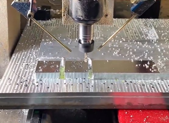
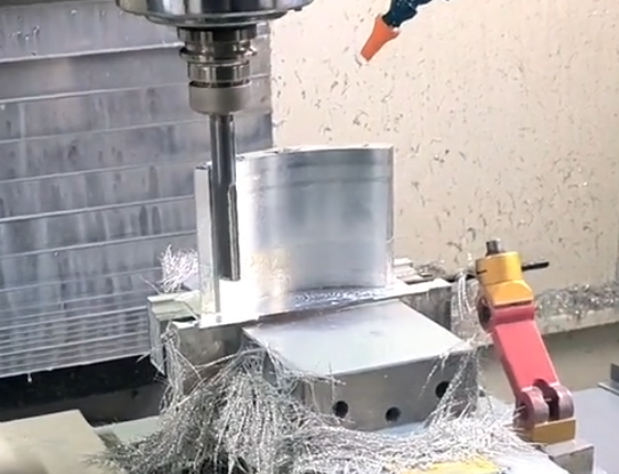
Chip Evacuation and Surface Integrity
Aluminum chips can be long and stringy or short and curled, depending on geometry and cutting conditions. Long chips can wrap around tools, causing scratches and re-cutting.
Key practices:
Use through-spindle coolant or air for deep cavities and high-speed slotting to prevent chip packing. In drilling and tapping, prioritize chip evacuation by using drills designed for aluminum with polished flutes and appropriate point geometry. For horizontal machining centers or lathes, leverage gravity and chip conveyors to direct chips away quickly.
Process Planning and Setup Optimization
Systematic process planning minimizes handling, setup time, and non-cutting activities, all of which directly affect cost per part.
Operation Sequencing
Sequence operations to stabilize the part early and maintain sufficient support throughout machining. Typical approach for prismatic components:
Reference surface generation: First create accurate and stable datum surfaces for subsequent clamping and measurement. Roughing: Remove bulk material while clamping is robust; leave uniform allowances on all critical surfaces. Semi-finishing: Normalize stock distribution to reduce dimensional changes during finishing. Finishing: Perform final passes with optimized parameters and minimal stock removal to achieve target tolerances and surface finish.
For turned parts, rough turning typically precedes drilling and boring, followed by finishing passes on critical diameters and faces.
Fixture Design for Aluminum Parts
Aluminum’s relatively low stiffness and thermal expansion coefficient require suitable clamping to prevent distortion and local deformation.
Considerations:
Use larger contact areas and controlled clamping force to avoid imprinting or bending thin-walled sections. Design fixtures that access multiple faces in a single setup to reduce re-clamping. Soft jaws and custom nests made from aluminum or polymer materials help distribute pressure and protect surfaces. When machining thin webs or pockets, sequence roughing to leave ribs and supports in place until late stages, then remove them with lighter finishing passes.
Programming Techniques to Reduce Machining Cost
CAM programming has a direct impact on cycle time, tool life, and part quality. Efficient tool paths minimize air cutting, regulate chip load, and protect tools from sudden load changes.
Tool Path Strategies
For aluminum milling, use:
Smooth entry/exit moves: Helical or ramped entries reduce tool shock compared to vertical plunging. Constant engagement tool paths: Trochoidal or adaptive milling ensures uniform cutter load and avoids spikes when entering corners. Arc-based linking moves: Replace sharp corners with arcs to maintain consistent feed and avoid sudden deceleration.
Feedrate Optimization and Cornering
In corners and confined areas, instantaneous chip thickness can increase if feed is not reduced. CAM systems that automatically slow feed in corners preserve tool life and surface quality.
Practical guidelines:
Specify maximum allowable engagement angle or chip thickness; let the CAM system adjust feed accordingly. Use feed ramping when entering full-width cuts or deep slots to prevent overload. On machines with limited acceleration, adjust jerk and acceleration parameters to maintain programmed feed in long cuts and avoid excessive slowdown.
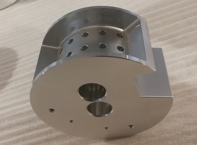
Dimensional Accuracy and Surface Finish Control
Cost-effective machining depends on achieving tolerance and finish requirements consistently, avoiding rework or scrap. Aluminum’s thermal behavior and potential for burr formation require targeted control measures.
Thermal Effects and Compensation
Aluminum expands appreciably with temperature changes. Allowable expansion ΔL for a dimension L can be estimated using:
ΔL = α × L × ΔT
where α is the coefficient of thermal expansion (approximately 23 × 10⁻⁶ /K for many alloys) and ΔT is the temperature change in Kelvin or °C.
To maintain dimensional accuracy:
Maintain stable coolant and workshop temperatures where possible. Avoid heavy roughing and finishing in the same local area without a cooling interval on tight-tolerance features; schedule finishing later in the program. Use machine-based thermal compensation when available and verify it regularly with reference artifacts.
Burr Control and Deburring Cost
Burr formation on edges and small features is common in aluminum and can become a significant hidden cost if manual deburring is extensive.
Reduction measures:
Optimize cutting direction and tool path to push burrs toward non-critical edges or sacrificial stock. Use sharp tools with appropriate rake to minimize burr size. For holes, consider back chamfering tools or duplex drilling strategies that integrate deburring.
Tool Life Management and Cost Tracking
Managing tool life systematically prevents unexpected breaks, maintains surface quality, and stabilizes cost per part. Recording tool performance over time allows refinement of parameters and tool choices.
Tool Life Targets and Monitoring
Tool life may be defined by flank wear, surface finish deterioration, dimensional drift, or the onset of chatter. For aluminum, flank wear and built-up edge are common limiting factors.
Set clear criteria for tool change based on:
Maximum acceptable wear land width on flank face (for example, 0.2–0.3 mm for many carbide tools). Maximum number of parts or cutting length per tool under stable conditions. Surface roughness parameters (Ra, Rz) or visual inspection standards for critical surfaces.
Use machine tool counters or tool management systems to track cumulative cutting time or number of cuts. Adjust tool life targets when geometry, coolant, or parameters are modified, and ensure operators follow the same criteria.
Cost per Edge and Tool Inventory
To evaluate cost-effectiveness, calculate cost per edge and cost per part:
Cost per edge = Tool price / number of usable edges.
Cost per part = (Total tool cost over a batch) / number of good parts.
Standardize on a limited set of tools that cover a broad range of operations where possible, as this reduces inventory, simplifies programming, and can improve purchase terms. However, avoid using overly general tools that compromise efficiency in demanding operations such as high-speed roughing or micro-feature machining.
Machine Tool Capability and Maintenance
Machine capability sets the upper limit of economical cutting conditions. A well-maintained machine achieves better accuracy, repeatability, and tool life.
Spindle Speed and Power Requirements
Aluminum machining benefits from spindles capable of higher speeds (e.g., 10,000–20,000 rpm or higher) combined with stable bearings and adequate power. For small diameter tools (e.g., 3–8 mm), high rpm is essential to reach recommended cutting speeds.
Assess actual spindle torque at operating speeds to avoid stalling or overheating during heavy roughing. Use the machine’s torque–speed curve to match tool diameter and cutting parameters to available power.
Geometric Accuracy and Preventive Maintenance
Backlash, axis straightness, and rotary axis accuracy influence feature position and surface quality. Establish routine checks:
Laser or ballbar tests at scheduled intervals to monitor positioning accuracy and repeatability. Spindle runout and vibration checks to ensure good surface finish and tool life. Maintenance of coolant systems, chip conveyors, and way covers to avoid contamination and unexpected downtime.
Inspection, Quality Control, and Feedback Loops
Effective inspection ensures parts meet specifications while providing data to refine machining parameters and process design.
In-Process and Post-Process Inspection
Use in-machine probing for datum verification, tool length and radius checks, and critical feature measurement where cycle time permits. This reduces manual handling and helps catch deviations early.
Post-process inspection with coordinate measuring machines (CMM), optical systems, or specialized gauges should focus on:
Features with tight tolerances or functional significance. Surfaces subject to mating, sealing, or fatigue load. Dimensional relationships that are sensitive to clamping conditions or thermal effects.
Data-Driven Process Improvement
Record deviations from nominal dimensions, tool life data, and surface finish results per batch. Analyze recurring issues such as systematic size offsets, localized surface defects, or frequent burrs. Adjust machining parameters, tool paths, or clamping schemes based on this feedback, and document revised best practices for future setups.
Cost Evaluation and Continuous Optimization
Cost-effective aluminum machining requires ongoing evaluation of the relationship between cycle time, tool cost, material utilization, and quality-related expenses.
Breakdown of Machining Cost Components
Key cost components include:
Material cost: Stock material minus scrap value. Machine cost: Machine-hour rate multiplied by cutting and non-cutting time. Tooling cost: Amortized tool cost over the number of parts. Labor cost: Setup time, in-process supervision, and secondary operations such as deburring. Quality cost: Inspection, rework, and scrap.
Estimate the contribution of each component and prioritize improvements where the impact is largest, such as cycle time reduction on high-volume parts or scrap reduction on high-value alloys.
Standardization and Documentation
Standardized practices reduce engineering time, simplify training, and improve repeatability.
Recommendations:
Maintain parameter sheets per alloy and operation type (roughing, finishing, drilling, tapping). Store proven tool lists, preferred fixtures, and CAM templates for common part families. Update documentation when process improvements are implemented to avoid reverting to less efficient methods in future jobs.
