
CNC, short for Computer Numerical Control, is a method of controlling machine tools and production equipment by using a computer to execute preprogrammed numerical instructions. In CNC systems, the motion of mechanical components such as axes, spindles and tool changers is governed by digital commands (typically expressed as G-code and M-code) instead of manual operation or purely mechanical templates.
CNC technology transforms design data into precise machine movements, enabling repeatable, high-accuracy manufacturing of parts with complex geometries. It is widely used in processes such as milling, turning, drilling, grinding, cutting and additive or hybrid operations across industries like aerospace, automotive, medical device, electronics and general engineering.
Working Principle and Core Definition of CNC
The core concept definition of CNC is to translate numerical data representing geometry and process parameters into coordinated, controlled motion of multiple machine axes and auxiliary functions. CNC integrates hardware (mechanical structure and drives) and software (control logic and interpolation algorithms) to automatically execute machining cycles.
Basic Workflow
- Creation of part geometry in CAD software
- Generation of toolpaths and CNC program in CAM software or via manual coding
- Transfer of CNC program to the machine control
- Setting of workpiece zero point, tool offsets and process parameters
- Automatic execution of the program by the CNC control, guiding tool and workpiece motion
Motion Control Principle
CNC controls use interpolation algorithms (such as linear and circular interpolation) to convert path data into continuous axis motion. The control unit reads each block of the CNC program, calculates setpoints for position, speed and acceleration, and sends commands to servo drives. Feedback from encoders or linear scales allows closed-loop control for accurate positioning.
Key control tasks include:
- Axis coordination for multi-axis simultaneous motion
- Speed and acceleration planning to adhere to machine limits
- Compensation for backlash, lead screw errors and thermal expansion
Key Components of a CNC System
A CNC system combines several major subsystems that operate together to achieve automated machining. Each component has a specific technical role and set of parameters.
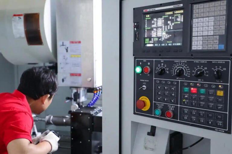
CNC Control Unit
The CNC control unit (CNC controller) is the core of the system. It receives, interprets and executes numerical instructions, performs motion calculations and coordinates machine functions.
Main functions include:
- Program interpretation (G-code, M-code, macro commands)
- Path interpolation and motion profile generation
- Real-time control of servo drives and spindle
- Management of I/O signals for coolant, clamps and auxiliary devices
- User interface for program editing, diagnostics and parameter settings
Servo Drives and Motors
Servo drives convert command signals from the CNC control into controlled motion of servo motors. The servo system ensures high dynamic response and positional accuracy.
Technical characteristics typically include:
Position feedback via encoders or linear scales, high-resolution measurement, torque and speed control, and parameter tuning for stiffness and damping.
Machine Structure and Axes
The mechanical structure includes the machine bed, guideways, ball screws or linear motors, spindle units and other moving assemblies. Each controlled axis (X, Y, Z and possible rotational axes A, B, C) is driven by a servo motor and guided by precision mechanical components.
Structural considerations include stiffness, vibration behavior, thermal stability and geometric alignment to maintain accuracy and surface quality.
Sensors, Feedback and I/O
CNC machines rely on various sensors and input/output devices:
- Limit switches and reference switches for axis homing
- Probes for workpiece and tool measurement
- Temperature sensors for compensation functions
- Pressure and flow sensors in lubrication and coolant systems
Types of CNC Machines
CNC technology is applied to many categories of machine tools and equipment. Different machine types address different machining tasks and geometric requirements.
| Machine Type | Typical Axes | Main Operations | Typical Applications |
|---|---|---|---|
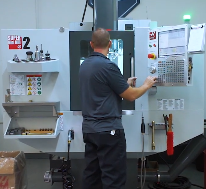
| CNC Milling Machine / Machining Center | 3–5 axes | Face milling, contouring, pocketing, drilling, tapping | Molds, precision components, complex housings |
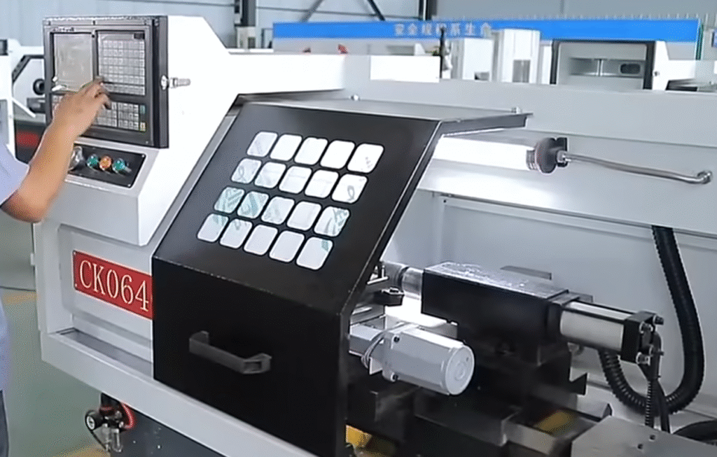
| CNC Lathe / Turning Center | 2–4 axes | Turning, facing, threading, grooving, boring | Shafts, bushings, rings and rotational parts |
| CNC Grinding Machine | 2–5 axes | Surface, cylindrical and profile grinding | High-precision surfaces, cutting tools, gauge parts |
| CNC EDM (Electrical Discharge Machining) | Typically 2–5 axes | Wire cutting, die sinking | Hard materials, intricate cavities, sharp internal corners |
| CNC Laser / Plasma / Waterjet Cutter | 2–5 axes | Cutting, piercing, contouring | Sheet metal cutting, sign making, structural parts |
| CNC Router | 3–5 axes | Routing, engraving, contouring | Wood, plastics, composites, furniture, signage |
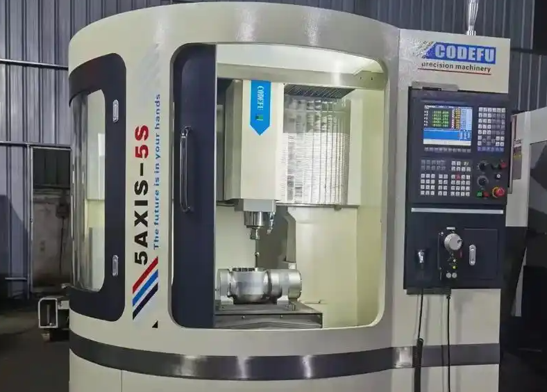
| Multi-Tasking / Mill-Turn Center | 5 or more axes | Combined turning and milling in one setup | Complex aerospace, automotive and medical parts |
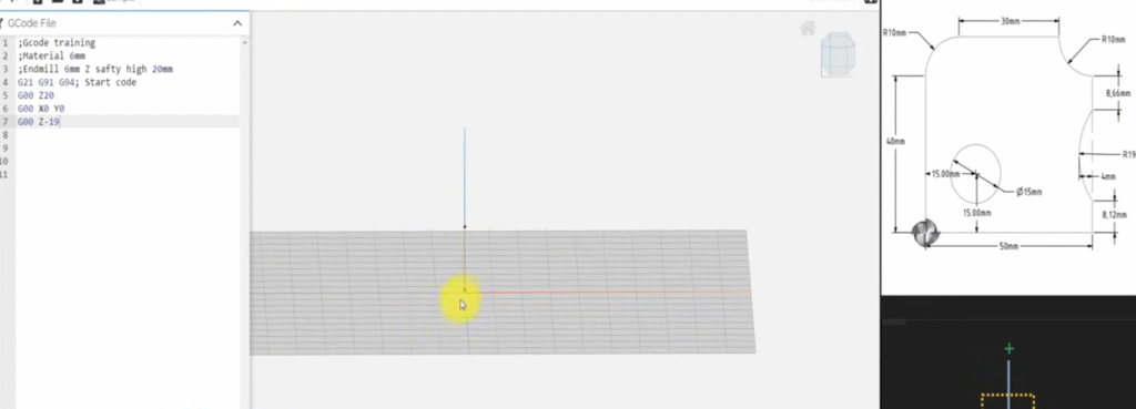
CNC Programming and G-Code
CNC programming defines the sequence of tool movements and auxiliary actions. The most common programming format is G-code, a standardized numerical control language, often generated by CAM software and then adjusted manually if necessary.
Program Structure
A CNC program typically consists of blocks (lines), each containing commands for motion, spindle, coolant and other functions. G-codes specify motion modes and coordinate systems, while M-codes control machine-level functions.
Core elements include:
- Preparation functions (G-codes) for motion mode and interpolation type
- Coordinates for target positions in absolute or incremental format
- Feed rates and spindle speeds
- Tool call commands and tool compensation
- Auxiliary functions such as coolant or chuck operation
Manual Programming Versus CAM
Manual programming involves directly writing G-code, especially useful for simple parts or rapid changes. CAM-based programming uses CAD models to automatically generate toolpaths and then post-processes them into CNC programs for specific machine controls.
Coordinate Systems and Reference Points
Coordinate systems define the spatial reference used to describe tool and workpiece positions. Reliable understanding of coordinates is a fundamental part of the CNC definition.
Machine and Workpiece Coordinates
Key coordinate systems include:
- Machine coordinate system: fixed to the machine, origin established by homing
- Workpiece coordinate system: defined by the operator, used to program part geometry
- Tool coordinate system: used for tool length and radius compensation
Precise setting of work offsets (such as G54–G59 on many controls) links the part drawing coordinates to the physical workpiece setup on the machine.
Accuracy, Repeatability and Related Parameters
CNC performance is characterized by parameters such as positioning accuracy, repeatability, surface finish quality and dynamic behavior. Understanding these aspects is essential when defining CNC capabilities.
| Parameter | Description | Typical Range (Representative) |
|---|---|---|
| Positioning Accuracy | Maximum deviation between commanded and actual position when moving from one point to another | ±0.002 mm to ±0.01 mm for many precision machines |
| Repeatability | Variation in reaching the same position repeatedly from the same direction | Within 0.001 mm to 0.005 mm typical |
| Axis Rapid Traverse Speed | Maximum non-cutting feed rate of each axis | Commonly 20–60 m/min, high-speed machines significantly higher |
| Feed Rate Range | Range of programmable cutting feed rates | From very low (e.g., 1 mm/min) up to several tens of m/min |
| Spindle Speed Range | Minimum to maximum spindle rotational speed | Example: 50–12,000 rpm, high-speed spindles >20,000 rpm |
| Tool Change Time | Time required to exchange tools via automatic tool changer | Approximately 1–5 seconds depending on system |
Auxiliary Systems in CNC Machines
In addition to motion control, CNC machines incorporate auxiliary systems that directly affect process stability and part quality.
Coolant and Chip Removal
Coolant systems deliver cutting fluid to the cutting zone to reduce temperature, lubricate and improve chip evacuation. Chip conveyors and chip augers remove chips from the machining area to maintain process reliability.
Tool Management
Automatic tool changers (ATC) store multiple tools in magazines or carousels. Tool management functions in the CNC control track tool life, offsets and tool substitution rules to ensure that a correct, measured tool is in place before machining begins.
Workholding and Clamping
CNC machines employ vises, chucks, fixtures and pallets to secure workpieces. Integration with the CNC control enables automated clamping, pallet change and workpiece referencing, improving throughput and repeatability.
Applications of CNC Technology
CNC is used wherever precise, repeatable and scalable machining is required. Definition of CNC encompasses a broad spectrum of manufacturing tasks across different materials and industries.
Industrial Applications
Typical application domains include:
- Aerospace: complex structural components, turbine blades, engine parts
- Automotive: engine blocks, transmission components, molds for body panels
- Medical: implants, surgical instruments, dental components
- Electronics: housings, heat sinks, connectors, precision mechanical parts
- General engineering: machine parts, tooling, jigs and fixtures
Material Processing Range
CNC machines process metals such as steel, aluminum, titanium and copper alloys, as well as non-metals including plastics, composites, ceramics, wood and graphite. Process parameters must be matched to material properties such as hardness, toughness and thermal conductivity.
Benefits and Technical Considerations of CNC
When defining CNC in a practical context, both advantages and technical considerations should be taken into account.
Key Advantages
- High dimensional accuracy and repeatability over large production runs
- Capability to manufacture complex geometries and free-form surfaces
- Reduced dependence on manual skill for basic operations
- Efficient changeover between different parts via program changes
- Integration capability with CAD/CAM and digital production systems
Technical Considerations and Constraints
Typical considerations include:
- Programming and setup require specialized knowledge and careful validation
- Machine capabilities (axis travel, spindle power, tool capacity) limit part size and complexity
- Improper selection of cutting data can lead to tool wear, vibration or surface defects
- Thermal effects and mechanical wear necessitate periodic calibration and maintenance
Selection and Configuration of CNC Systems
When defining requirements for a CNC machine or system, technical parameters, process tasks and integration needs should be precisely specified to match actual production demands.
Machine Capability Definition of CNC
Important configuration points include:
- Number and type of controlled axes, including rotary and additional axes
- Working envelope (X, Y, Z travel) and maximum part size
- Spindle power, torque curve and speed range
- Tool magazine capacity and tool interface standard
- Coolant type (flood, through-spindle, high-pressure) and chip handling
Control and Software Aspects
From the control perspective, the following aspects are key:
- Supported programming formats (standard G-code, conversational, macros)
- Interpolation functions (3-axis, 4-axis, 5-axis, spline interpolation)
- Interfaces to CAD/CAM, DNC and higher-level production systems
- Diagnostic, monitoring and logging functions for process supervision
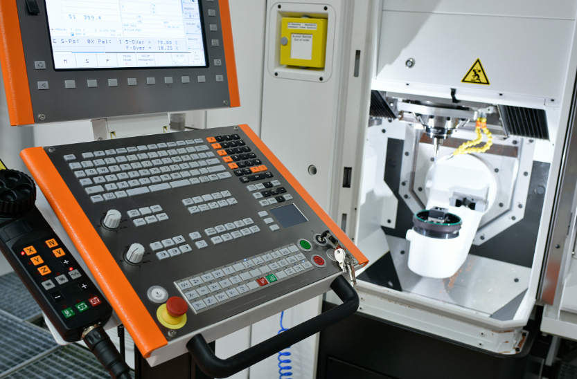
Safety and Operational Procedures
Safe operation is an integral part of CNC definition in industrial practice. CNC machines combine high forces, rotating tools and automated movements, requiring strict adherence to procedures.
Core operational aspects include:
- Use of safety guards, interlocks and emergency stops as provided by the machine
- Verification of programs in single-block or dry-run mode before full-speed operation
- Correct clamping of tools and workpieces to avoid collision or ejection
- Regular inspection of safety devices and confirmation of functional status

Summary of CNC Definition in Modern Manufacturing
CNC (Computer Numerical Control) can be defined as an integrated hardware and software system that uses digital numerical instructions to control machine motion, machining processes and auxiliary functions, enabling precise, automated and repeatable production of parts. It encompasses controllers, servo systems, machine structures, programming, coordinates, auxiliary systems and operational procedures.
This definition covers not only the abstract control principle but also the practical engineering aspects: machine types, accuracy parameters, programming methods, application fields, selection criteria and safety considerations. From single-piece production to large-batch manufacturing, CNC has become a core foundation of modern mechanical processing and precision engineering.
FAQ About the Definition of CNC
What does CNC stand for?
CNC stands for Computer Numerical Control, a manufacturing method where machines are controlled by computer programs rather than manual operation.
How does CNC differ from manual machining?
Unlike manual machining, CNC uses computer-controlled instructions to perform operations automatically, resulting in higher precision, repeatability, and efficiency.
What types of machines use CNC?
CNC is commonly used in machines such as mills, lathes, routers, grinders, and multi-axis machining centers.
Is CNC the same as automation?
CNC is a form of automation, but full automation may also include robotics, material handling, and in-process inspection systems.
What skills are required to operate CNC machines?
Operators need skills in machine setup, tooling, programming, and process monitoring. CNC programming is typically done using G-code or CAM software.
